Loading ...
Loading ...
Loading ...
3-4
n
Whirlpool Smart All-In-One Washer & Dryer
COMPONENT TESTING
For Service Technician Use Only
DANGER
Electrical Shock Hazard
Only authorized technicians should perform
diagnostic voltage measurements.
After performing voltage measurements,
disconnect power before servicing.
Failure to follow these instructions can result in
death or electrical shock.
TESTING WASHER COMPONENTS FROM THE
CONTROL
Before tesng any of the components, perform the following
checks:
• The most common cause for mis-diagnosed control failure
is poor connecons. Therefore, disconnecng, inspecng
and reconnecng wires will be necessary throughout test
procedures.
• All tests/checks should be made with a VOM or DVM
having a sensivity of 20,000 ohms-per-volt DC, or greater.
• Check all connecons before replacing components,
looking for broken or loose wires, failed terminals, or wires
not pressed into connectors far enough.
• IMPORTANT: Voltage checks must be made with all
connectors aached to the boards.
• Resistance checks must be made with power cord
unplugged or power disconnected, and with wiring harness
or connectors disconnected from the control.
• IMPORTANT: The following procedures may require the use
of needle probes to measure voltage. Failure to use needle
probes will damage the connectors.
TEST #1: Appiance Control Unit (ACU)
Power Check
This test checks for incoming and outgoing power to and from
Appliance Control Unit (ACU). This test assumes that proper
voltage is present at the outlet.
1. Unplug washer/dryer or disconnect power.
2. Visually check that all connecons to the RFI lter are
securely connected. See Figure 1, below.
3. Gently lay washer/dryer on its right side to access the
ACU. Remove AC shield and ACU cover.
4. Visually check that all connecons to the ACU are fully
inserted. See Figure 2, page 3-5.
5. If both visual checks pass, go to step 6.
6. Plug in washer/dryer or reconnect power.
7. With a voltmeter set to AC, check for line voltage at the
input of the RFI lter. See Figure 1.
¾ If line voltage is present, go to step 8.
¾ If line voltage is not present, verify the connuity of
the power cord. If it fails the connuity check, replace
the power cord.
8. With a voltmeter set to AC, check for line voltage at the
output of the RFI lter. See Figure 1.
¾ If line voltage is present, go to step 9.
¾ If line voltage is not present, replace the RFI lter.
9. With a voltmeter set to AC, check for input line voltage to
the ACU across pins 1 and 2 of connector J1. See Figure 2.
¾ If line voltage is present, go to step 10.
¾ If line voltage is not present, check harnesses and
connecons between the lter and the ACU. Visually
inspect inside connector housing for bent or damaged
terminals. Repair as necessary.
10. Check HMI input voltage:
With a voltmeter set to DC, verify that there is 12V
between pin 3 and 4 at J16.
¾ If there is 12V, go to step 11.
¾ If there is not 12V, disconnect J16 and recheck for 12V
between pin 3 and 4. If there is not 12V, replace the
ACU. If 12V returns, check ACU to HMI harness for
short. If harness is good, then replace the HMI.
11. Unplug washer/dryer or disconnect power.
12. Reassemble all parts and panels.
13. Perform the Service Diagnosc Mode Tests on page 2-3 to
verify repairs.
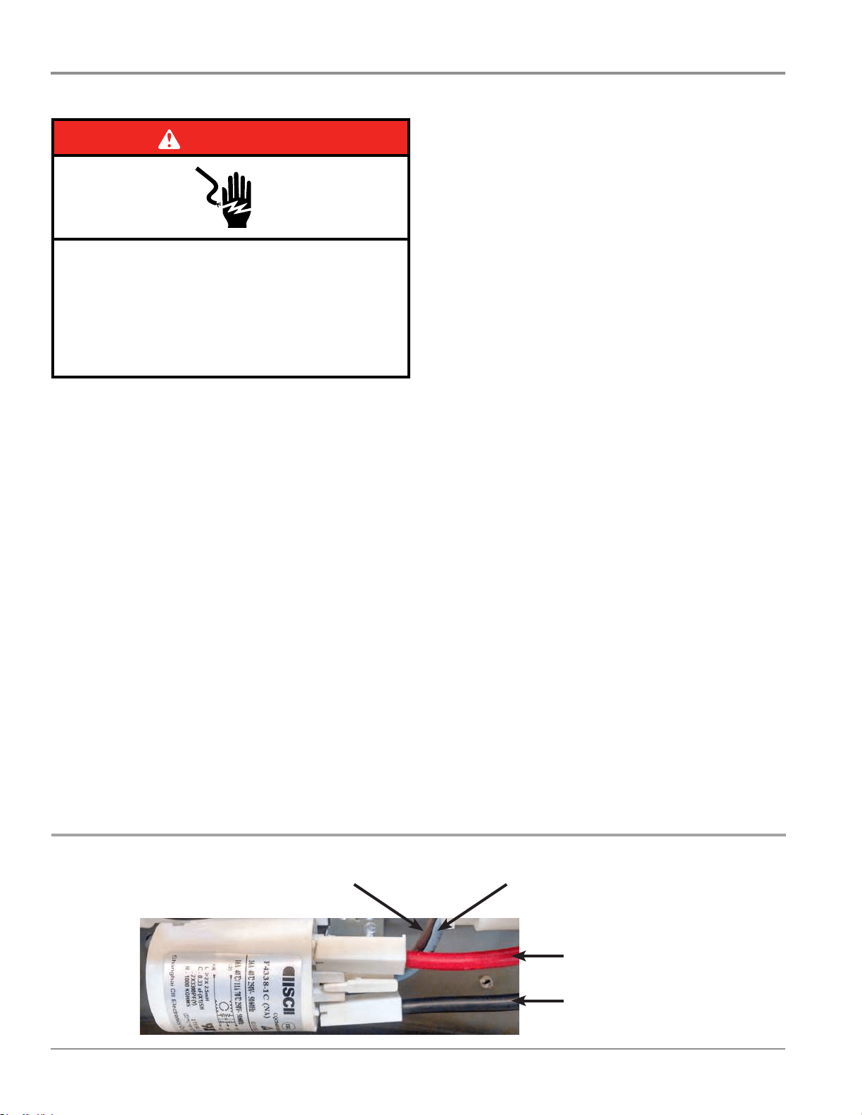
RFI FILTER - FIGURE 1
L2 Input to RFI Filter (Black Wire)
L2 Output to ACU J1, Pin 1 (Lt Blue Wire)L1 Output to ACU J1, Pin 2 (Brown Wire)
L1 Input to RFI Filter (Red Wire)
Loading ...
Loading ...
Loading ...