Loading ...
Loading ...
Loading ...
GAS
HOOK-UP
I
TESTING
AND
ADJUSTMENTS
CAUTION!
When
connectm
g
unit
to
P
ro
pa
ne
(LP)
gas.
make
certa1n
the
propan
e ta
nk
is
equipped
w1th
1ts
own
high-pressure
regul
at
or
in
a
ddi
tion
to
the
pressure
regulator
supplied
with
the
app
li
an
ce
.
The
pressure
of
the
gas
supp
l
ied
to
th
e a
ppli
an
ce
regulator
mus
t
no
t
exceed
14 (37 mb) water
column
. A
pressure
t
est
point
is
pro
v
id
ed
near
the
regu
l
ator
behmd
th
e
ki
ck
pl
ate
NATURAL
GA
S
REQUIREMENTS:
•
Inlet
Connection:
1/2"
N.P.
T.
•
Min.
5/8"
Dia.
Flex
Line.
•
Supply
Pressure:
6"
to
14"
W.C.
PROPANE
(LP
)
GAS
REQUIREMENTS:
• Inlet
Connection:
1/2"
N.P.T.
•
Min.
5/8"
Dia.
Flex
Line.
•
Supply
Pressure:
11"
to
14"
W.C.
• A
Regulator
is
required
at
the
LP
source
to
provide
a
maximum
of
14"
W.C.
pressure
to
the
range
regulator.
WARNING!
--
G
-
a
-
s-li_n_e_c_a-nn_o_t-~---ru-n--in-s-id_e_b_a_c-,kl
cover
of
range.
Run
gas
line
in
channel
in
back
HOOK
UP
• A
manual
shut
off
valve
must
be
installed
external
to
the
range
in
an
accessible
location
from
the
front
for
shutting
off
the
gas
supply
when
required.
•
The
supply
line
MUST
NOT
protrude
beyond
the
back
of
the
range.
•
Ensure
that
the
gas
supp
ly is
turned
O
FF
at
the
externa
l
shut-off
valve
before
connect
i
ng
t
he
r
ange.
•
The
gas
supply
co
nn
ect
ion
must
be
made
by
an
exper
i
enced
technician
and
in
accordance
wi
th
l
oca
l
codes
or
ordinances.
In
the
absence
of l
oca
l
codes
or
ord
i
nances,
pl
ease
refer
to
Nat
i
ona
l
Fuel
Gas
Code
ANSI
Z223.1/
NFPA54-Current
I
ssue.
•
The
range
is
supplied
with
its
own
pressure
regulator
that
has
been
permanently
rrounted
to
the
range
body.
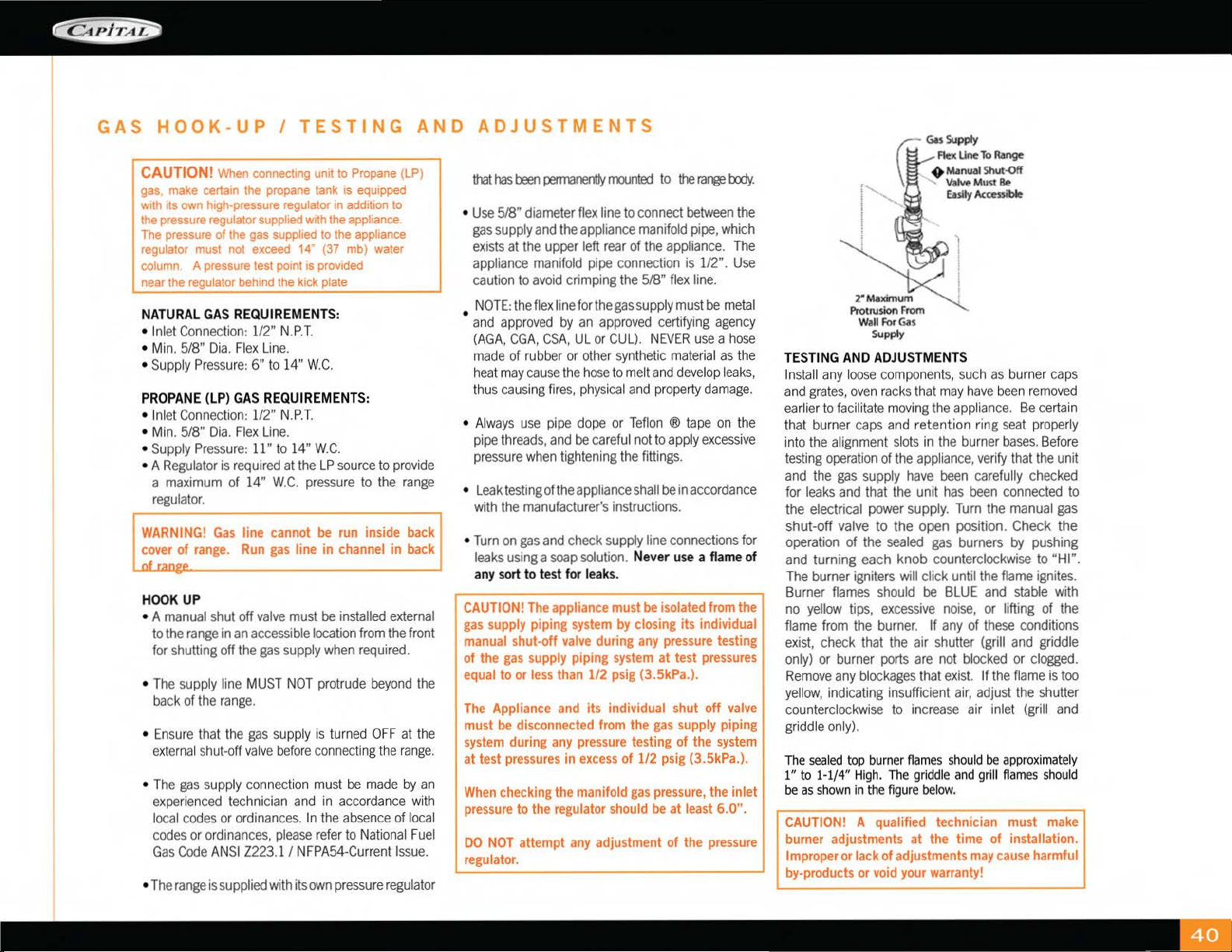
•
Use
518"
diameter
flex
line
to
connect
~tween
the
gas
supply
and
the
appliance
manifold
pipe,
which
exists
at
the
upper
left
rear
of
the
appliance.
The
appliance
manifold
pipe
connection
is
112".
Use
caution
to
avoid
crimping
the
5/8"
flex
line.
NOTE:
the
flex
line
for
the
gas
supply
must
be
metal
• and
app
r
oved
by
an
approved
cert
i
fying
agency
(AGA,
CGA,
CSA,
UL
or
CUL).
NEVER
use
a h
ose
made
of
ru
bber
or
other
synthet
ic
ma
t
erial
as
the
hea
t
may
cause
the
hose
to
me
lt
an
d
develop
l
eaks,
t
hu
s
causing
f
ir
es,
physica
l and
property
damage.
• Al
ways
use
pipe
dope
or
Tef
l
on
® t
ape
on
the
pipe
threads,
and
be
careful
not
to
apply
excessive
pressure
when
tightening
the
fittings.
•
Leak
testing
ofthe a
pplia
nee
sha
II
be
in
accord
a
nee
with
the
manufacturer's
instructions.
•
Turn
on
gas
and
check
supply
line
connections
for
leaks
using
a
soap
solution.
Ne
ver u
se
a fl
am
e of
any sort to t
es
t for le
ak
s.
CAUTION!
The
appliance
must~
isolated
from
the
I
gas
supply
piping
system
by
closing its individual
manual
shut-off
valve
during
any
pressure
testing
of the
gas
supply
piping
system
at test
pressures
equal
to
or
less
than
112
psig
(3
.
5kPa.)
.
The
Appliance
and
its individual shut off
valve
must
be
disconnected
from
the
gas
supply
piping
system
during
any
pressure
testing of the
system
at test
pressures
in
excess
of 1/2
psig
(3.5kPa.).
When
checking
the
manifold
gas
pressure,
the inlet
pressure
to the
regulator
should
be
at
least
6.0".
DO
NOT
attempt
any
adjustment of
the
pressure
regulator
.
GuSu
pply
Flex
line
To
Range
+
Manual
Shut-<:>tr
..._
V•IW
Must
Be
Easily
Accessi
ble
TESTING
AND
ADJUSTMENTS
I
nstall
any
l
oose
components,
such
as
burne
r
caps
and
grates,
ove
n
racks
that
may
have
bee
n
removed
earlier
to f
acili
tate
moving
the
app
lian
ce.
Be
certain
that
burner
caps
an
d retention ri
ng
seat
proper
ly
i
nto
the
alignment
slots
in
the
burne
r
bases.
Be
f
ore
testing
operation
of
the
app
l
iance,
verify
that
the
unit
and
the
gas
supply
have
been
carefu
ll
y
checked
for
leaks
and
that
the
unit
has
been
connected
to
the electrical
power
supply.
Turn
the
manual
gas
shut-off
valve
to the open position. Check the
operation
of
the
sealed
gas
burners
by
pushing
and
turning each knob
counterclockwise
to
"HI".
The
burner
igniters
will
click until
the
flame
ignites.
Burner
flames
should
be
BLUE
and
stable
with
no
yellow
tips,
excessive
noise,
or lifting
of
the
flame
from
the
burner.
If
any
of
these
conditions
exist
check
that
the
air
shutter
(grill
and
griddle
only)
or
burner
ports
are
not
blocked
or
clogged.
Remove
any
blockages
that
exist.
If
the
flame
is
too
yellow,
indicating insufficient
air,
adjust
the
shutter
coun
t
erclockwise
to
increase
air inl
et
(grill
and
griddle
only).
The
sealed
top
burn
er
flam
es
s
hould
be
approximately
1"
to
1-1/4"
Hi
gh
.
Th
e
griddl
e
and
gr
i
ll
flames
should
be
as
shown
in
th
e
figur
e be
low
.
CAUTION!
A qualified technician
must
make
burner adjustments at the time
of
installation.
Improper
or lack of
adjustments
may
cause
harmful
by-products
or
void
your
warranty!
----------1
Loading ...
Loading ...
Loading ...