Loading ...
Loading ...
Loading ...
STEP
4:
INSTALLING
ANTI-TIP
DEVICE
For
all
Ra
n
ges,
an
anti-tip
device
MUST
be
installed
as
per
these
instructions.
@@
WARNING!
•
ALL
RANGES
CAN
TIP
•
IN
J
UR
Y
TO
PERSONS
COULD
RESULT
• I
NST
ALL
ANTI-TIP
DEV
I
CES
PACKED
W
IT
H
RANGE
•
SEE
IN
STALLAT
I
ON
I
NSTRUCT
I
ON
WARNING:
RANGE
TIPPING
HAZARD!
•
All
ranges
can
ti
p
and
injury
can
r
esult.
To
prevent
accide
n
tal
tipping of the
ra
n
ge,
attach it
to
the
fl
oor,
wall
or
cab
in
et
by
ins
talling
the
Anti-Tip
Device
supp
l
ied.
• A
risk
of
tip-over
may
exist
if
the
appliance
is
not
in
sta
ll
ed
in
accorda
n
ce
with th
ese
in
str
u
ct
ion
s.
• If
the
range
is
pulled
away
from
the
wall
for
cl
ean
in
g,
service
or
any
ot
her
reason,
ens
ur
e
that
the
Anti-Tip
Dev
i
ce
is
properly
re-engaged
when
the
ra
n
ge
is
pushed
back
aga
in
st t
he
wall.
In
the
event
of
ab
n
orma
l
usage
(such
as
a
person
stand
in
g,
sitting,
or l
ea
nin
g
on
an
open
door),
fa
il
ure
to
take
this
precaution
can
resu
lt
in
tipping
of the
range.
Personal
injury might
result
from
sp
ill
ed
h
ot
li
q
ui
ds
or
from
the
range
i
tse
l
f.
WARNING:
ELECTRICAL
SHOCK
HAZARD!
•
Use
extreme
caution
when drilling hol
es
into
the
wa
ll
or
floor.
There
may
be
concealed
electrical
wires
l
ocated
beh
ind
the
wa
ll
or
und
er
the
fl
oor.
•
Identify
th
e
electrical
circuits that
co
ul
d
be
affected
by
the
installation
of
the
Anti
-
Tip
Dev
i
ce,
then
turn
off
power
to
these
c
ir
cu
i
ts.
•
Fa
ilure
to
follow
th
ese
in
s
tru
c
ti
ons
may
result
in
electrical
shock
or
other
personal
injury.
CAUTION:
PROPERTY
DAMAGE!
•
Contact
a q
uali
fi
ed
in
sta
ll
er or contractor
to
determine
the
proper
method
fo
r dr
illi
ng
holes
through
th
e
wall
or
floor
materia
l
(such
as
ceramic
tile,
hardwood,
marble,
etc.)
•
DO
NOT
slide
range
across
unprotected floor.
•
Fa
il
ure
to
follow
these
in
str
uctions
may
result
in
damage
to
wall
or
floor
coverings.
TOOL
S
NEEDED
FOR
INSTALLATION
OF
ANTI-TIP
DEVICE!
1.
Screwdriver
,
Phillips
2.
Dr
ill
, el
ectr
ic
or
h
and
3.
Meas
urin
g t
ape
or
ru
l
er
4.
1/8" dr
ill
bit
(wood
or
metal
wall
or
floor)
5.
3116"
anchor
s,
drywall,
or
concrete,
2
eac
h (not
required
if
mounting
bracket
is
being
attached
to
solid
wood
or
metal.
6.
Hammer
7.
Penc
il
or
ot
h
er
marker
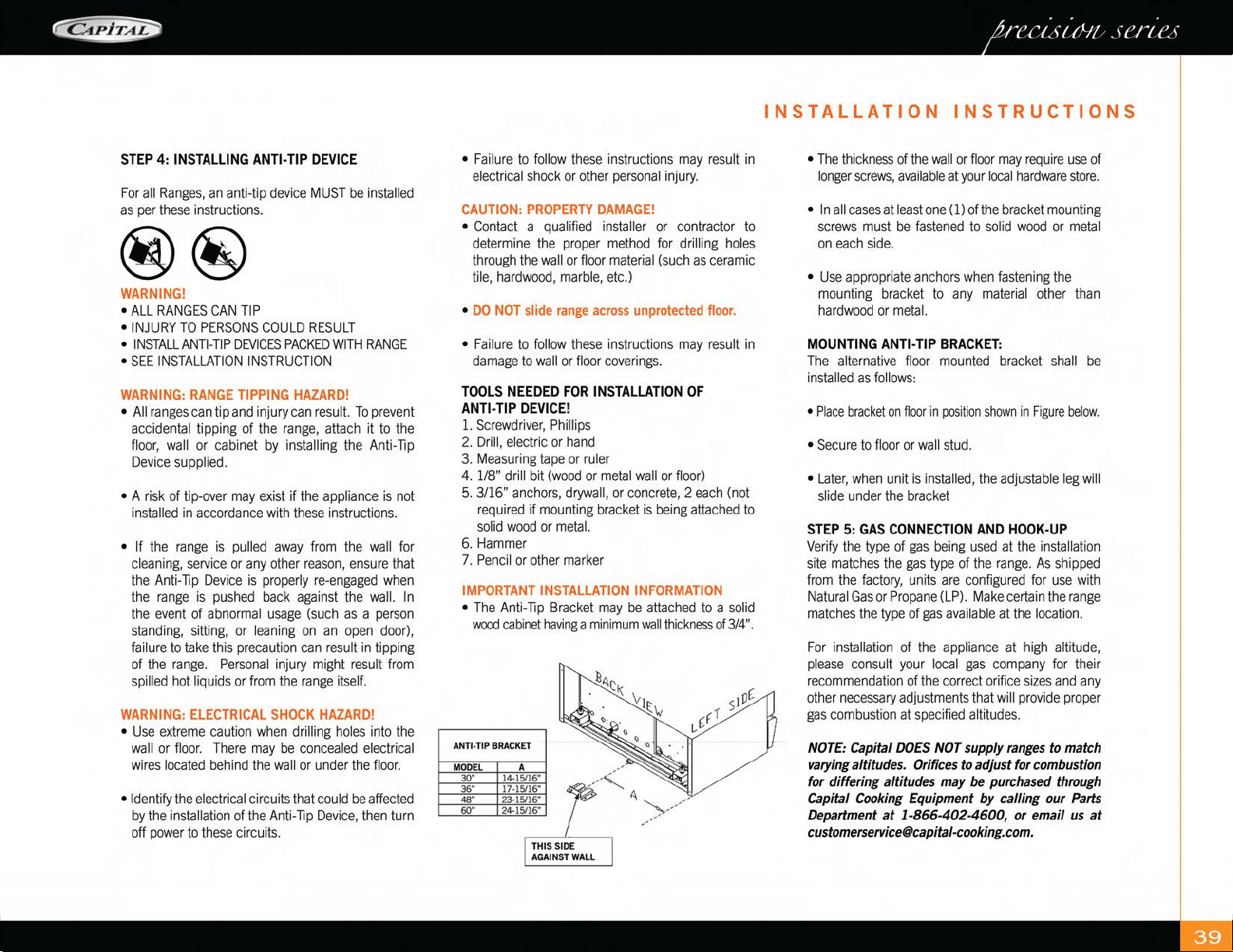
IMPORTANT
INSTALLATION
INFORMATION
•
Th
e
Anti-Tip
Br
acket
may
be
a
tta
ch
ed
to
a
solid
wood
cabinet
having
a
min
i
mum
wall
thickness
of
3/4".
ANT
I·
TIP
BRACKET
MOD
EL
A
30" 14
·151
16"
36" 17·
15116"
48
"
23
·1511
6"
60" 24
·15116"
INSTALLATION
INSTRUCTIONS
•
The
thi
ck
n
ess
of
the
wall
or
fl
oo
r
may
require
use
of
longer
screws,
ava
i
lab
le
at
your
local
ha
r
dware
store.
•
In
all
cases
at l
east
one
(1) of
the
bracket
mount
i
ng
screws
must
be
fastened
to
so
li
d
wood
or
meta
l
on
each
side.
•
Use
appropriate
anchors
wh
en
fasten
i
ng
the
mounting
br
acket
to
any
mater
ial
other
than
hardwood
or
metal.
MOUNTING
ANTI-TIP
BRACKET:
Th
e
alternative
floor
mounted
bracket
shall
be
in
sta
ll
ed
as
fo
ll
ows:
• Pl
ace
bracket
on
floo
r in
pos
iti
on
shown
in Fi
gure
be
l
ow.
•
Secure
to
fl
oor
or
wa
ll
stud.
•
Late
r,
when
unit
is
installed,
the
ad
ju
stab
le l
eg
w
ill
slide
under
the
bracket
STEP
5:
GAS
CONNECTION
AND
HOOK-UP
Verify
the
type
of
gas
being
u
sed
at
the
in
sta
ll
ation
si
te
matches
the
gas
type
of
the
r
ange
.
As
s
hi
pped
from
the
f
ac
t
ory,
units
are
configured
for
use
with
Natura
l
Gas
or
Propane
(L
P).
Make
certa
in
the
range
matches
the
type
of
gas
ava
il
ab
le at
the
location.
Fo
r
installation
of t
he
appliance
at
high
a
ltitu
de,
pl
ease
consult
your
local
gas
company
for
the
ir
r
ecommendat
i
on
of
the
correct
orifice
sizes
and
a
ny
ot
h
er
necessary
adjustments
that
will
provide
prope
r
gas
comb
u
st
ion at
spec
ifi
ed
altit
ud
es.
NOTE: Capital
DOES
NOT supply ranges to match
varying altitudes. Orifices to adjust for combustion
for differing altitudes may
be purchased through
Capital Cooking Equipment by calling our Parts
Department
at
1-866-402-4600,
or email us
at
Loading ...
Loading ...
Loading ...