THE
ART
OF
PRECISION™
USE
AND
CARE
/INSTALLATION
GUIDE
J.::~::f::f:::::i~
erie.r R a n g e
Gas
Manual Clean with Convection
Proudly
~
Made
in
USA

A
SPECIAL
MESSAGE
TO
OUR
CUSTOMERS
Dear
Valued
Customer,
Congratulations on making a smart choice!
You
have joined an elite group of cooking enthusiasts who demand only the very best from their
appliances. A Capital Cooking appliance promises years of cooking enjoyment and
outstanding
performance
, allowing cooks everywhere
to create
culinary memories that last a lifetime.
Because
of
the
unique
features
found
in
our
appliances,
we
urge
you
to
read
this
manua
l thoroughly before installati
on
and use.
And
please retain this manual for future reference;
it
is
an
invaluable
guide
to
help
you
better
understand
your
Capital
Cooking
appliance.
Since your satisfaction is our topmost priority, please feel free to contact our service experts.
You
may reach us toll free at 866.402.4600,
or dial the factory dir
ect
at 562.903-1168.
You
can fax
us
a list of your concerns, comments, and/or compliments at 562.903-1167, or drop
us an
email at customerservi[email protected]. Feel free to also write us at 13211 East Florence
Ave.
Santa
Fe
Springs,
CA
90670.
Our products are proudly designed and man
uf
actured in America, and we
trust
that
our
strict
adherence to the highest quality
assurance standards will provide you with years of trouble free, gourmet cooking.
Happy Cooking!
Chairman
Capital Cooking Equipment, Inc.
TABLE OF CONTENTS
Precision F
ea
tur
es
Models
Warnings
Safety
Practices
I
Electrical,
General
Safety
Practices
1
Cooking
Oven
Parts
Identificat
ion
Range
Parts
Identification
Using
The
Range
-top I
Power-floTM
Burners
Using
The
Rangetop
Using
Your
Oven
Using
Your
Oven
-
Self
Cl
ean
Mode
care
And
Maintenance
care
AND
Maintenance
I
Locating
Rating
Plate
Troubleshooting
Installation Instructions
Table
Of
Contents
Service
I Warranty
3
4-5-6-7
8
9
10-11
12
13
14
15-16-17
17-18-19-20
21-22
23
24
25-26
27
28
42
-;
-~
:......,
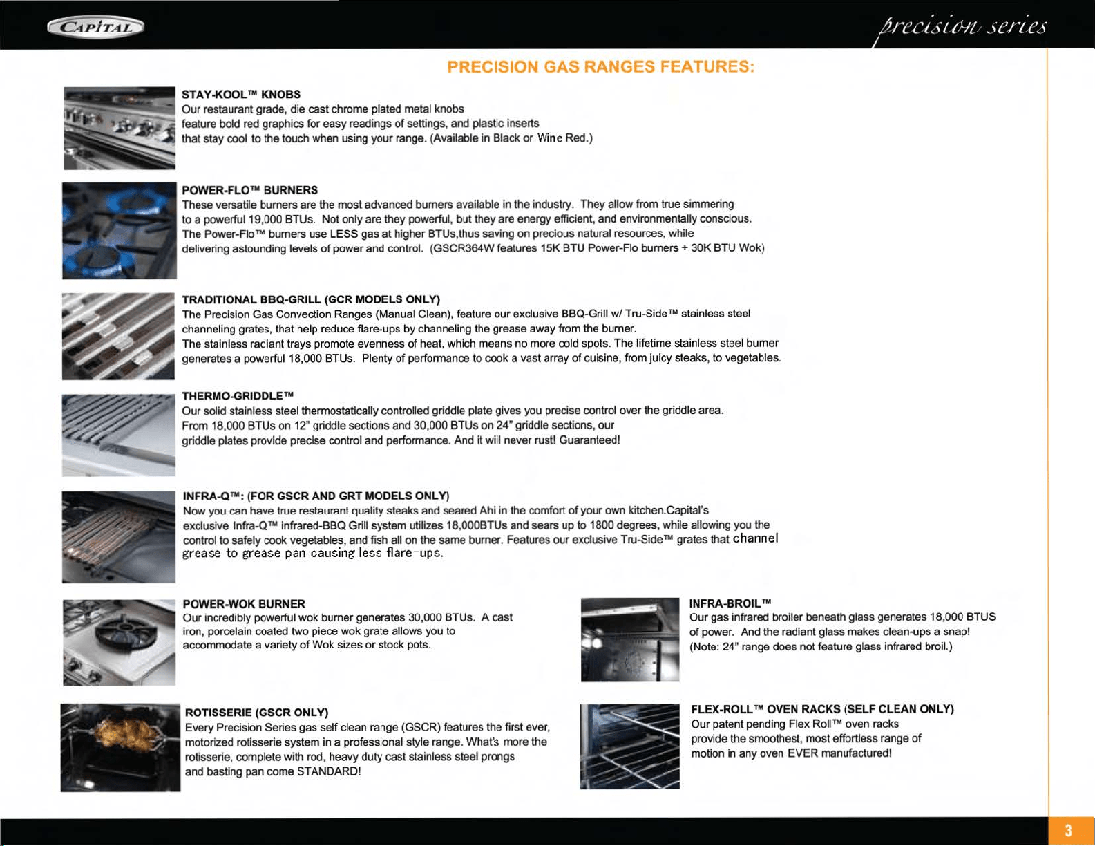
PRECISION GAS RANGES FEATURES:
STA
Y
·KOOL
TM
KNOBS
Our
restaurant grade, die cast chrome plated metal knobs
feature bold red graphics for
easy
readings
of
settings, and plastic inserts
that stay cool to the touch when using your range.
(Available in Black
or
Wine Red.)
POWER·FLO
TM
BURNERS
These versatile burners are the most advanced burners available in the industry. They allow from true simmering
to a powerful19,000 BTUs.
Not
only are they powerful,
but
they are energy efficient,
and
environmentally conscious.
The Power-Flo
TM
burners use LE
SS
gas
at
higher BTUs,thus saving
on
precious natural resources, while
delivering astounding levels
of
power
and
control. (GSCR364W features 15K BTU Power-Flo
burners+
30K
BTU Wok)
TRADITIONAL BBQ-GRILL (GCR MODELS
ONLY)
The Precision Gas Convection Ranges (Manual Clean), feature
our
exclusive
BBQ
-Grill
w/
Tru-Side rM stainless steel
channeling grates, that help reduce flare-ups by channeling the grease away from the burner.
The stainless radiant trays promote evenness
of
heat, which means
no
more cold spots. The lifetime stainless steel burner
generates a powerful18,000 BTUs. Plenty
of
performance to cook a vast array
of
cuisine, from juicy steaks, to vegetables.
THERMO-GRIDDLE
TM
Our
solid stainless steel thermostatically controlled griddle plate gives you precise control over the griddle area.
From 18,000 BTUs on 12" griddle sections and 30,
000
BTUs on 24" griddle sections,
our
griddle plates provide precise control
and
performance. And it will never rust! Guaranteed!
INFRA.Q
TM:
(FOR
GSCR
AND
GRT
MODELS ONLY)
Now
you can have true restaurant quality steaks and seared Ahi in the comfort
of
your own kitchen.Capital's
exclusive
Jnfra-QTM
infrared-BBQ Grill system
ut
ilizes 18,000BTUs and sears
up
to 1800 degrees, while allowing you the
control to safety cook vegetables, and fish all on the same burner. Features
our
exclusive Tru-Si
deTM
grates that c
ha
nn el
grease
to
grease
pan
causing
les
s
flare-ups.
POWER-WOK BURNER
Our
incredibly powerful wok burner generates 30,000 BTUs. A cast
iron, porcelain coated two piece wok grate allows you to
accommodate a variety
of
Wok sizes
or
stock pots.
ROTISSERIE
(GSCR
ONLY)
Every Precision Series gas self clean range (GSCR) features the first ever,
motorized rotisserie system in a professional style range.
What
's more the
rotisserie, complete with rod, heavy duty cast stainless steel prongs
and basting pan come STANDARD!
INFRA
-
BROIL
TM
Our
gas
infrared broiler beneath glass generates 18,
000
BTUS
of
power. And the radiant glass makes clean-ups a snap!
(Note: 24" range does not feature glass infrared broil.)
FLEX-ROLL TM OVEN RACKS (SELF CLEAN ONLY)
Our
patent pending Flex
Rolln.o
oven racks
provide the smoothest, most effortless range
of
motion
in
any oven EVER manufactured!
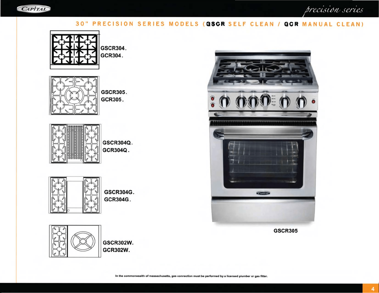
30"
PRECISION
SERIES
MODELS
(
QSCR
SELF
CLEAN
I
OCR
MANUAL
CLEAN}
..
~
......
+-ill
GSCR304.
GCR304 .
GSCR305.
GCR305.
GSCR304Q.
GCR304Q.
GSCR304G.
GCR304G.
GSCR302W.
GCR302W.
In
the
commonwealth
of
massachusetts,
gas
connection
must
be
performed
by
a licensed
plumber
or
gas
fitter
.
GSCR305
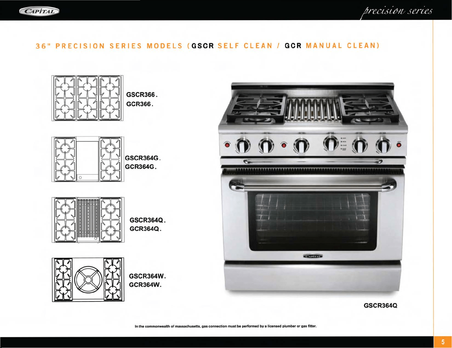
36"
PRECISION
SERIES
MODELS
{
GSCR
SELF
CLEAN
I
GCR
MANUAL
CLEAN)
GSCR366 .
GCR366.
GSCR364G.
GCR364G.
GSCR364Q.
GCR364Q .
GSCR364W.
GCR364W.
In the
common-alth
of
massachusetta,
gas
connection must be performed
by
a
lic
ensed plumber
or
gas fitter.
GSCR364Q
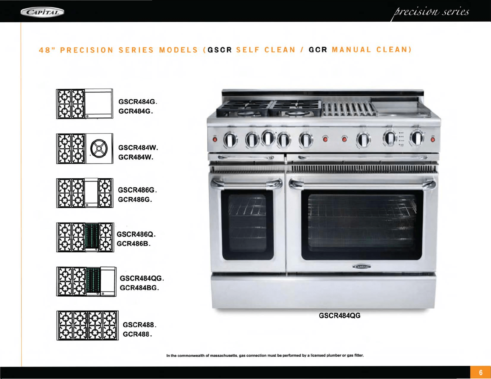
48"
PRECISION
SERIES
MODELS
(
GSCR
SELF
CLEAN
I
GCR
MANUAL
CLEAN)
GSCR484G.
GCR484G .
GSCR484W.
GCR484W.
GSCR486G.
l£t:i£1
~::1
~
GCR486G.
GSCR486Q.
GCR486B .
GSCR484QG.
GCR484BG.
GSCR484QG
In the
common-alth
of
muuc:huMIIs
, g
..
c:onnec11on
must be
performed
by
a licensed plumber
or
gas fitter.
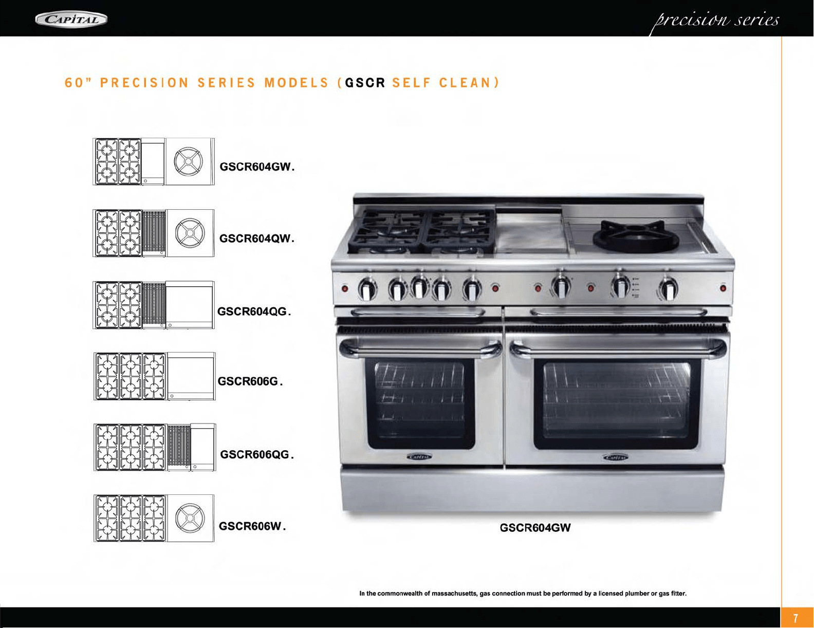
60"
PRECISION
SERIES
MODELS
(
GSCR
SELF
CLEAN)
1
1m~o
1
® 11 GSCR604GW.
® GSCR604QW.
GSCR604QG.
GSCR606QG.
GSCR604GW
In the commonwealth
of
massachusetts,
gas
connection must be performed
by
a licensed plumber
or
gas fitter.
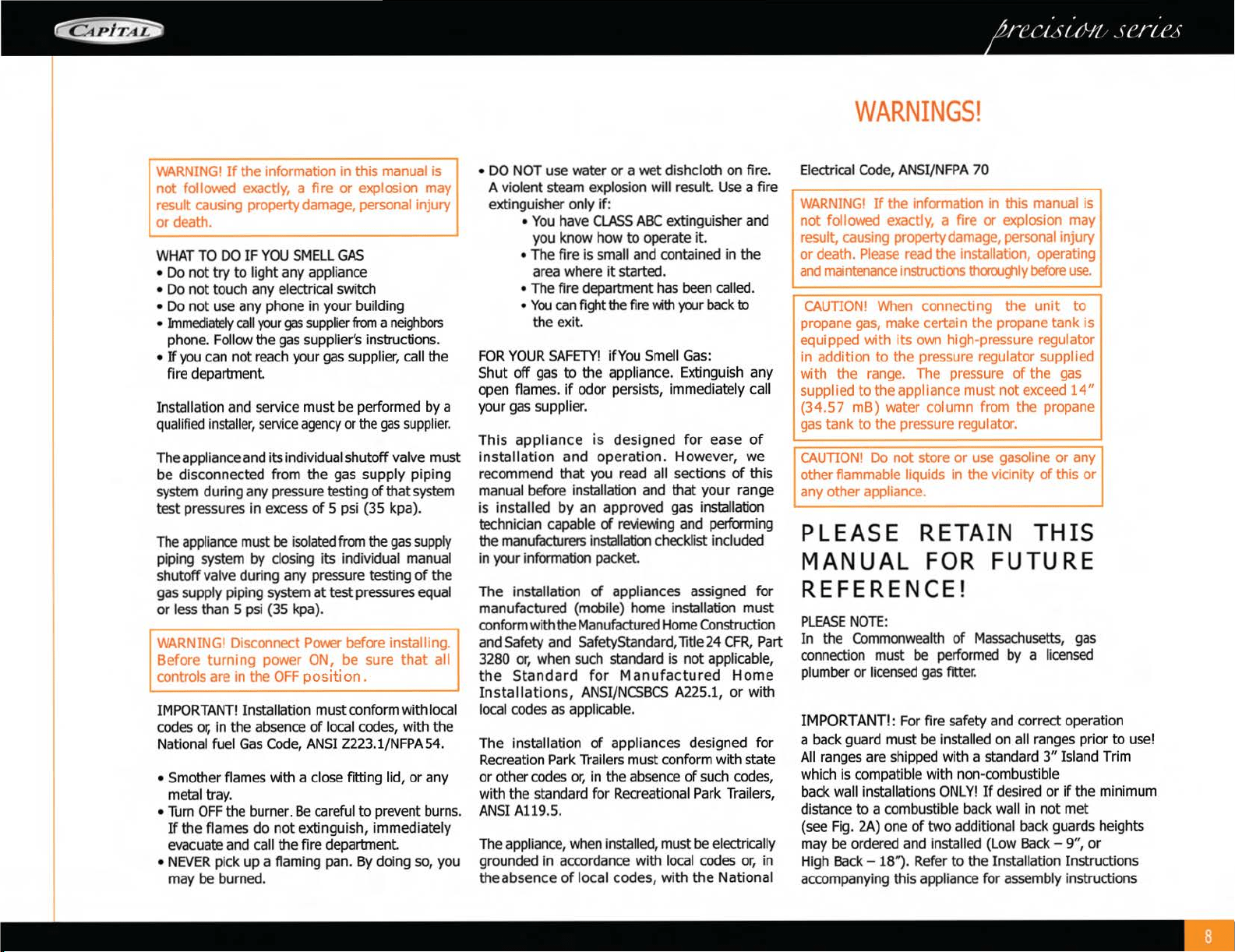
WARNING!
If
the information in this manual is
not
followed exactly, a fire
or
explosion may
result causing property damage, personal injury I
or
death.
WHAT
TO
DO
IF
YOU
SMELL
GAS
• Do
not
try
to
light any appliance
• Do
not
touch any electrical switch
• Do
not
use any phone in your building
•
Immediately
call
~r
gas
supplier
from
a
neighbors
phone. Follow the gas supplier's instructions.
•
If
you
can not reach your
gas
supplier, call the
fire department
Installation and service must
be
performed by a
qualified
installer,
service
agency
or
the
gas
supplier.
The appliance and its individual shutoff valve must
be disconnected from the gas supply piping
system during any pressure testing
of
that system
test pressures in excess
of
5 psi (35 kpa).
The
appliance must
be
isolated from the
gas
supply
piping system by closing its individual
manual
shutoff valve during any pressure testing
of
the
gas supply piping system
at
test pressures equal
or
less than 5 psi (35 kpa).
RNING! Disconnect Power before installing.
fore
turning
power ON,
be
sure
that
all
ntrols are in the
OFF
position.
IMPORTANT!
Installation must conform with local
codes
or,
in the absence
of
local codes, with the
National
fuel
Gas
Code,
ANS
I Z223.1/NFPA54.
• Smother flames with a close fitting lid,
or
any
metal tray.
•
Turn
OFF
the burner.
Be
careful to prevent burns.
If
the flames
do
not
extinguish, immediately
evacuate and call the fire department
•
NEVER
pick up a flaming pan.
By
doing so, you
may
be burned.
•
DO
NOT use water
or
a wet dishcloth on fire.
A
violent steam explosion will result.
Use
a fire
extinguisher only if:
•
You
have
CLASS
ABC
extinguisher and
you know how
to
operate it.
• The fire is small and contained in the
area where
it
started.
• The fire department has been called .
•
You
can
fight
the
fire
Wth
you
r
back
to
the exit.
FOR
YOUR
SAFETY!
ifYou Smell
Gas:
Shut
off
gas
to
the appliance. Extinguish any
open flames.
if
odor persists, immediately call
your
gas
supplier.
This
appliance
is
designed
for
ease
of
installation
and
operation.
However, we
recommend that
you
read all sections
of
this
manual before installation and that your range
is
installed
by
an approved gas installation
technician capable
~
reviewing and performing
the manufacturers installation checklist included
in your information packet.
The installation
of
appliances assigned for
manufactured (mobile) home installation must
conform with the Manufactured Home Construction
and Safety and SafetyStandard,litle 24
CFR,
P
art
3280
or,
when such standard is not applicable,
the
Standard
for
Manufactured
Home
Installations,
ANSI/NCSBCS
A225.1,
or
with
local codes as applicable.
The installation
of
appliances designed for
Recreation Park Trailers must conform with state
or
other codes
or,
in the absence
of
such codes,
with the standard for Recreational
Park
Trailers,
ANSI A119.5.
The
appliance, when installed, must
be
electrically
grounded in accordance with local codes
or,
in
the absence
of
local codes,
with
the National
WARNINGS!
Electrical Code, ANSI/NFPA 70
I
WARNING!
If
the information in this manual is I
not
followed exactly, a fire
or
explosion may
result, causing property damage, personal
injury·
or
death.
Please
read the installation, operating I
and
maintenance
instructioos
th<roughly
before
use.
CAUTION! When connecting the
unit
to
propane gas, make certain the propane
tank
is
equipped with
its
own high-pressure regulator
in
addition
to
the
pressure regulator supplied
with the range. The pressure
of
the gas
supplied
to
the appliance
must
not
exceed 14 "
(34.57
mB)
water column from the propane
gas tank to the pressure regulator.
CAUTION!
Do
not
store
or
use gasoline
or
any
other flammable
liquids in the vicinity
of
this
or
any other appliance.
THIS
FUTURE
PLEASE RETAIN
MANUAL
FOR
RE
FERENCE!
PLEASE
NOTE:
In
the Commonwealth
of
Massachusetts,
gas
connection must
be
performed
by
a licensed
plumber
or
licensed
gas
fitter.
I MPORTANT!: For fire safety and correct operation
a back guard must
be
installed on all ranges prior
to
use!
All
ranges are shipped with a standard
3"
Island Trim
which is compatible with non-combustible
back
wall installations
ONLY!
If
desir
ed
or
if
the minimum
distance to a combustible back
wall in
not
met
(see Fig. 2A) one
of
two
additional back guards heights
may
be
ordered and installed (Low
Back
- 9",
or
High
Back
- 18'1. Refer
to
the Installation Instructions
accompanying this
appliance for assembly instructions
SAFETY
PRACTICES
I
ELECTRICAL,
GENERAL
ELECTRICAL
SA
FETY
:
Electrical
Requirements
and
Grounding
Instructions
NOTE:
ALL
MODELS.
IN
CASE
OF
AN
ELECTRICAL
FAILURE
If
for
any
reason
a
gas
control
knob
is
turned
ON
and
there
is
no
electric
power
to
operate
the
electronic
igniters
on
the
range
burners,
turn
O
FF
the
gas
control
knob
and
wa
it 5
minu
t
es
for
the
gas
to
dissipate
before
lighting
the
range
burner
manually.
To
li
ght
the
range
burne
rs
ma
n
ua
lly, carefully
hold
a
lighted
match
to
the
burner
ports
and
turn
the
gas
control
knob
to
HI.
During
a
power
failure,
you
can
manually
light
the
standard
range
burners
on
l
y,
but
each
must
be
lit
with
a
match.
Note
: For
Prec
ision
Gas
Ran
ges,
the
gas
oven,
grill,
Thermo-griddle
1
"'
and infrared
oven
broiler
burners
CANNOT
be
lit
manually during a
power
failure.
WARNING!
Do
not under any circumstances
cut
or
remove
the separate ground wire or the third
(ground) prong from the
powe
r cord plug.
PLEA
SE
READ
CAREFULLY
:
All
gas
self
clean
range
models
require
an
electrical
circuit
rated
at
120
volts,
60
Hz.,
and
20
Amps.
(VER
I
FY)
For
personal
safety,
this
appliance
must
be
connected
to
a
proper
ly
grounded
and
polarized
electrical
power
supp
l
y.
Always
di
sco
nn
ect
the
electrical
plug
from
the
wall
receptacl
e
before
servicing
t
hi
s
unit.
See
Insta
ll
a
ti
on I
nstructions
for
electrical
requirements
and
grounding
instructions
.
It is
the
persona
l
responsibility
and
obligation
of
you,
the
user,
to
have
this
appliance
connected
to
the
el
ectr
i
ca
l
power
supply
in
accordance
with
the
National
Electrical
Code
and/or
applicable
local
codes
and
ordinances
by
a
qualified
electrician.
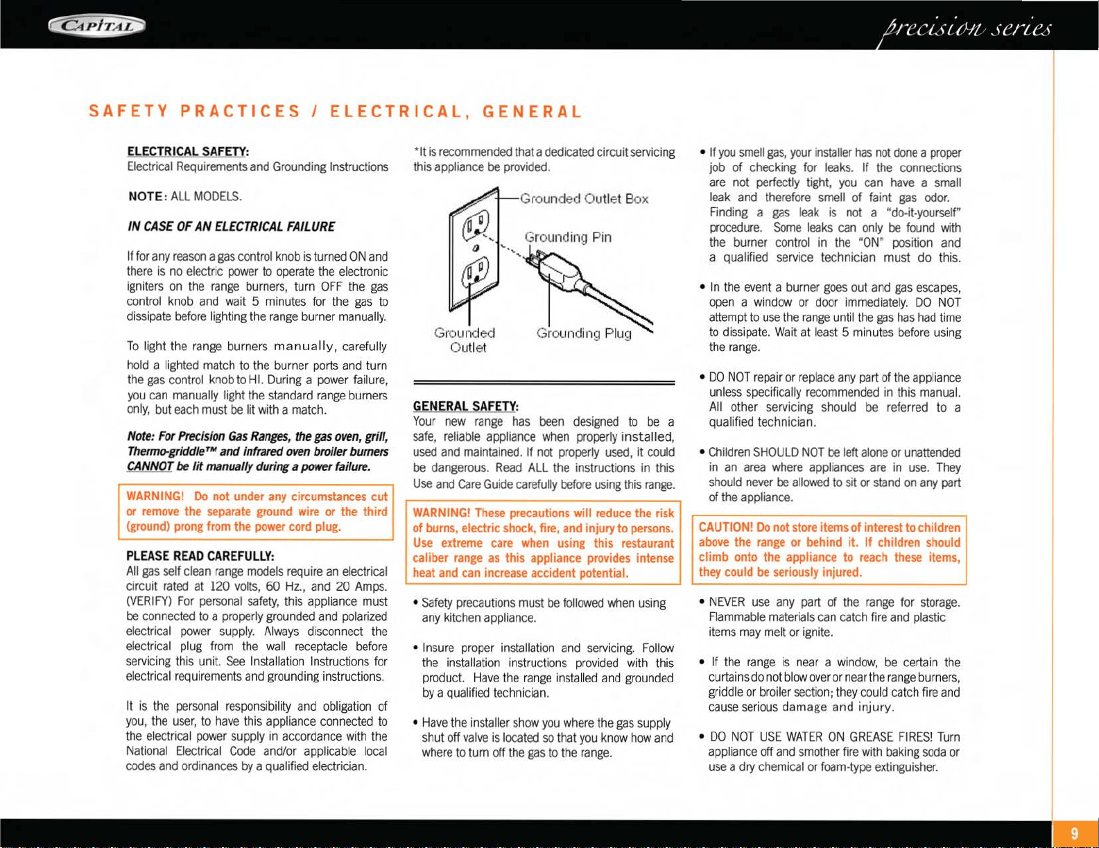
*It
is
recommended
that
a
dedicated
circuit
servicing
this
appliance
be
provided.
Grounded
Outlet
GENERAL SAFE Y:
Gro unded Outlet
Bo
x
Grounding Pin
Your
new
range
has
been
designed
to
be
a
safe,
reliable
appliance
when
properly
installed,
used
and
maintained.
If
not
properly
used,
it
could
be
dangerous.
Read
ALL
the
instructions
in
this
Use
and
Care
Guide
carefully
before
using
this
range.
I
WAR
NING! These precautions
will
reduce the risk I
of
burns, electric shock, fire, and injury to persons.
Use
extreme care when using this restaurant
caliber
range
as
this appliance provides inte
nse
heat and can increase accident potential.
•
Safety
precautions
must
be
followed
when
using
any
kitchen
appliance.
• I
nsure
proper
installation
and
servicing.
F
ollow
the
installation
i
nstr
uc
ti
ons
pr
ov
i
ded
w
ith
this
product.
Have
th
e ran
ge
in
sta
ll
ed
and
grounded
by
a
qualified
technician.
•
Have
the
installer
show
you
where
the
gas
supply
shut
off
va
l
ve
is
located
so
that
you
know
how
and
where
to
turn
off
the
gas
to
the
range.
• If
you
smell
gas,
your
i
nstaller
has
not
done
a
proper
job
of
checking
for
leaks.
If
the
connections
are
not
perfectly
tight,
you
can
have
a
small
leak
and
therefore
smell
of
faint
gas
odor.
Finding
a
gas
leak
is
not
a "
do-it-yourself"
procedure.
Some
leaks
can
only
be
found
with
the
burner
control
in
the
"ON"
position
and
a qualified
service
technician
must
do
this.
• In
the
event
a
burner
goes
out
and
gas
escapes,
open
a
window
or
doo
r i
mmed
i
ate
l
y.
DO
NO
T
attemp
t to
use
the
r
ange
unt
il
the
gas
has
had
t
ime
to
di
ss
i
pate.
Wa
it
at
least
5 m
in
utes
before
us
in
g
the
range.
•
DO
NOT
r
epair
or
rep
l
ace
any
part
of
the
appliance
unless
spec
ifi
ca
ll
y
recommended
in this
manual.
All
other
servicing
should
be
referred
to
a
qualified technician.
•
Children
SHOULD
NOT
be
left
alone
or
unattended
in
an
area
where
appliances
are
in
use.
They
should
never
be
allowed
to
sit
or
stand
on
any
part
of
the
appliance.
CA
UTION!
Do
not store items of interest
to
children
above the
range
or behind it.
If
child
ren
should
climb onto the appliance to
reach
these items,
t
hey
could
be
seriously
in
jured.
•
NEVER
use
any
part
of
the
range
for
storage.
F
lammable
materials
can
catch
fire
and
plastic
items
may
melt
or
ignite.
• If
the
range
is
n
ear
a w
in
dow,
be
certain
th
e
curtains
do
not
blo
w
over
or
near
the
ran
ge
b
urn
er
s,
griddle
or
broiler
section;
they
could
catc
h
fire
and
cause
serious
damage
and
injury
.
•
DO
NOT
USE
WATER
ON
GREASE
FIRES!
Turn
appliance
off
and
smother
fire
with
baking
soda
or
use
a dry
chemical
or
foam-type
extinguisher.
•
NEVE
R
let
clothing,
potholde
r
s,
or
other
flammable
materials
come
into
contact
with
or
too
close
to
any
element,
burner,
or
burner
grate
unt
il
it
has
coo
l
ed.
Fab
ri
c
may
i
gn
i
te
and
r
esu
lt
in
pe
r
sona
l
inju
ry.
COOKING
SAFETY:
•
USE
ON
LY
DRY
PO
T
HOLDERS
.
Moist
or
damp
potho
l
de
rs
on
hot
surfaces
may
cause
burns
from
the
steam.
Do
not
use
a
towe
l
or
other
bu
lk
y
cloth
in
pl
ace
of
po
t
holders.
Do
not
let
potho
l
ders
touch
h
ot
el
eme
n
ts,
h
ot
bu
rn
er
s,
or
burner
grates
.
•
FOR
PERSONAL
SAFETY,
wear
proper
apparel.
Loose
fitting
garments
or
hanging
sl
eeves
should
n
eve
r
be
worn
w
hil
e
using
this
app
li
an
ce
.
Some
sy
nth
et
ic
fab
ri
cs
are
highly
flammable
and
should
not
be
worn
w
hil
e
cook
in
g.
•
DO
NOT
use
aluminum
foil
as
a s
hi
eld
against
food
sp
ill
s
or
drippings
around
the
burners
or
cont
rol
pane
l ar
ea
.
Thi
s
cou
ld
obst
ru
ct
the
flow
of
comb
u
st
i
on
and
ventilated
air.
This
can
damage
the f
ini
sh of the
range.
WARNING!
This
appliance
is
for
cooking!
Based
on
safety
considerations,
never
use
the
range
to
warm
or
heat
a
room.
Such
use
can
damage
the
range.
•
DO
N
OT
TOUCH
THE
BURNER
GRATES
OR
THE
IMMEDIATE
SURROUNDING
AREAS
adjacent
to
the
burners.
When
in
use
these
areas
may
become
hot
enough
to
cause
burns.
•
NEVER
leave
the
range
unattended
when
using
hi
gh
flame
settings.
Bo
il-
overs
cause
smoking
and
greasy
sp
i
lls
that
may
ignite.
More
importantly,
if
the
burner
flames
are
smothered,
unburned
gas
will
escape
into
the
room.
See
inside
front
cover
regarding
gas
l
eaks.
•
ONLY
certain
types
of gl
ass,
heat
proof
gl
ass-
ceram
i
c,
ceramic
earthenware
or
other
glazed
utensils
are
suitable
for
range
use.
Other types
SAFETY
PRACTICES
I
COOKING
of
utensils
may
break
wi
th
sudden
temperature
changes.
Use
only
on
low
or
medium
heat
settings
accord
i
ng
to
the
utens
il
manufacturer's
direct
i
ons.
•
DO
NOT
HEAT
UNOPENED
FOOD
CONTAINERS
.
A
buildup
of
pressu
re
may
cause
the
containe
r
to
burst.
•
DURING
COOKING,
set
the
burner
control
so
that
the
fl
ame
heats
on
ly
the
bottom
of
the
pan
and
does
not
extend
beyond
the
bottom
of
the
pan
.
•
USE
CAUTION
to
ensure
that
drafts
like
those
from
forced
air
vents
or
fans
do
not
bl
ow
flammable
materials
toward
the
flames
or
push
the
flames
so
that
they
extend
beyond
the
edges
of
the
pot.
•
ALWAYS
use
utens
il
s
that
have
fl
at
bottoms,
large
enough
to
cover
the
burner
.
The
use
of
undersized
utensils
could
expose
a
portion
of
the
flame
and
may
result
in
ignition
of
clothing.
It
is
also
a
waste
of
gas.
•
TO
MINIMIZE
BURNS,
i
gni
t
ion
of
flammable
materials
and
unintentional
spills,
position
handles
of
utensil
in
ward
so
that
it
does
not
extend
over
adjacent
work
areas,
cooking
areas
or
the
edge
of
the
range
.
• H
OLD
THE
HANDLE
of
the
pan
to
prevent
movement
of
the
utensil
when
stirring
food.
•
DO
NOT
USE
the
Infra-gr
ill
™
BBQ
top
section
for
cooking
excess
i
vely
fatty
meats
or
products
that
promote
flare-ups.
•
GREASE
IS
FLAMMABLE.
Let
hot
grease
cool
before
attempting
to
handle
it.
Avoid
letting
grease
deposits
to
collect.
Clean
after
each
use.
•
KEEP
BURNER
PORTS
CL
EAN.
This
is
essential
for
proper
lighting
and
ma
int
enance
of
the
burners.
It
is
necessary
to
cl
ean
the
burner
ports
when
there
is
a
boil
over
or
when
the
burner
does
not
light
though
the
electronic
igniters
click.
•
CLEAN
THE
RANGE-TOP
SECT
I
ON
WI
TH
CAUTION
.
Avo
id
steam
burns;
do
not
use
a
wet
sponge
or
clot
h to
cl
ean
the
range
wh
i
le
it
is
hot.
Some
cleaners
produce
noxious
fumes
if
applied
to
a
hot
surface.
Follow
directi
ons
provided
by
the
cl
eaner
manufacturer.
•
BE
SURE
ALL
RANGE
CONTROLS
ARE
TURNED
OFF
and
the
range
is
cool
before
using
any
type
of
aeroso
l
cleaner
on
or
around
the
range.
The
chemical
that
produces
the
spraying
action
cou
l
d,
in
the
presence
of
heat,
ignite
or
cause
metal
parts
to
corrode
.
Only
an
a
uth
o
ri
zed
service
technician
should
perfo
rm
Service.
Technicians
must
di
sconnect
the
power
supply
before
servicing
this
unit.
• CL
EAN
THE
VE
NTI
LATOR
HOOD
and
filters
above
the
range
frequently
so
grease
deposits
from
cook
in
g
vapors
do
not
accumulate
on
th
em.
•
IN
CASE
OF
FI
RE
or
when
in
t
en
t
ionally
using
"flaming"
liquor
or
other
spirits
on
the
range,
follow
hood
manufacturer's
in
structi
ons.
• I
NSTALL
A
SMOKE
DETECTOR
in
or
near
the
kitchen.
•
TURN
THE
KNOB
CONTRO
L
TO
OFF
if a b
urn
er
goes
out
and
gas
escapes.
Open
a wi
ndow
or
door.
DO
NOT
attempt
to
use
the
range
unt
il
the
gas
has
had
time
to
dissipate.
WARNING!
To
reduce
the
risk
of tipping of the
appliance,
it
must
be
secured
by
a
properly
installed
anti-tip
device.
Verify
that
the
anti-tip
device
is
engaged
per
installation
instructions
(note:
anti-tip
device
is
required
on
all
gas
ranges.)
•
When
using
the
oven:
DO
NOT
touch
the
int
er
i
or
surfaces
of
the
oven
or
the
exte
ri
or
area
immediately
surrounding
the
door.
Interior
oven
surfaces
become
hot
enough
to
cause
burns.
The
heat
deflector,
which
deflects
heat
away
from
the
range
and
the
trim
on
the top
and
sides
of
the
oven
door,
will
also
be
hot
when
the
oven
is in
use.

SAFETY PRACTICES I COOKING
•
Place
oven
racks
in
desired
position
while
oven
is
cool.
If
a
rack
must
be
removed
while the
oven
is
hot,
do
not
let
the
potholders
contact the
hot
infrared
burner.
1.
Remove
all
packing
materials and
labels
from
your
appliance.
If
the
installer
has
not
set
up
your
appliance,
please
do
it
before using it.
2.
Place
the
oven
racks
in
the proper position
•
Use
care
when
opening
the
oven
door;
let before turning
on
the
oven.
hot
steam
or
air
escape
before removing or
replacing
foods.
•
DO
NOT
remove
the
door
gasket.
It
is
essential
for a
good
seal
du
r
ing
baking.
•
BE
CAREFU
L not to
damage
the
gla
ss
c
overi
ng
the
Infrared
broiler
in
the
gas
oven.
If
the
glass
is
damaged,
air
can
enter
the
distribution
box
behind
the
glass,
possibly
resulting
in
an
explosion.
• In the event that
personal
clothing
catches
fire,
DROP
AND
ROLL
immediately
to
extinguish
flames.
•
DO
NOT
obstruct the path
of
combustion
or
ventilation
air.
•
For
safety
reasons
and
to
avoid
equipment
damage,
never
sit,
stand,
or
lean
on
any part
of
the
range.
•
Service
should
only
be
performed
by
a
qualified,
Factory
Authorized
Service
Technidan.
Technidans
must
disconnect
the
power
supply
before
servicing
this
unit.
CALIFORNIA
PROPOSITION
65
WARNING:
The
burning
of
gas
cooking
fuel
generates
some
by
products
which
are
on
the
list
of
substances
which
are
known
by
the
State
of
California
to
cause
Cancer
or
reproductive
harm.
Ca
l
ifornia
law
requires
business
to
warn
customers
of
potentia
l
exposure
to
these
substances
.
To
minimize
exposure
to
these
substances,
always
operate
this
unit
according
to
the
instructions
contained
in
this
booklet
and
provide
good
ventilation
to
the
room
when
cooking
with
gas.
For
correct
rack
position,
check
your
recipe.
The
most frequently
used
position
is
number
2.
The
rack
positions
are
numbered from the bottom
to the top
as
in
the floors
of
a building.
CAUTION!
Do
not
use
aluminum foil to
cover
the
oven
racks
or
to line
the
oven.
Heat
can
be
trapped
beneath
the foil, this
can
cause
damage
to the
oven
and
food
may
not
cook
correctly.
3.
Before
BAK
I
NG
and
BRO
I
UNG:
Turn
on the
oven
and
broiler burners
one
at a
time for
20
to
30
minutes
each.
This
bums
off the
manufacturing
oils
used
by the factory. T
urn
the
oven
burner
on
to 450°F
and
then the broiler
burner
on
to "Broil".
Be
sure
to turn
on
the
ventilator
above
your
range
while these burners
are
on,
as
there will
be
an
odor.
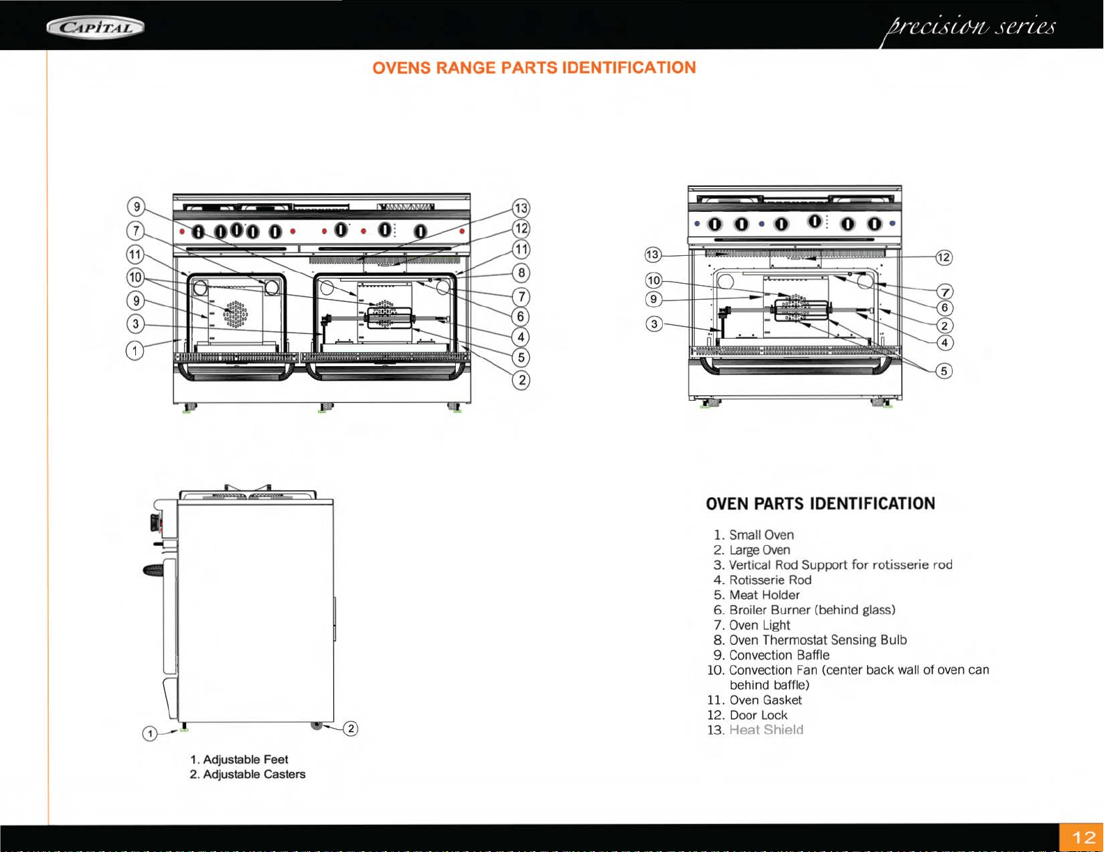
OVENS RANGE PARTS IDENTIFICATION
OVEN PARTS IDENTIFICATION
1.
Small Oven
2.
Large
Oven
3. Vertical
Rod
Support
for
rotisserie rod
4. Rotisserie Rod
5. Meat Holder
6. Broiler Burner (behind glass)
7.
Oven
Light
8.
Oven
Thermostat Sensing Bulb
9. Convection Baffle
10.
Convection
Fan
(center back
wa
ll of oven can
behind
baffle)
11.
Oven
Gasket
12. Door Lock
13.
Heat
Shield
1. Adjustable
Feet
2. Adjustable Casters
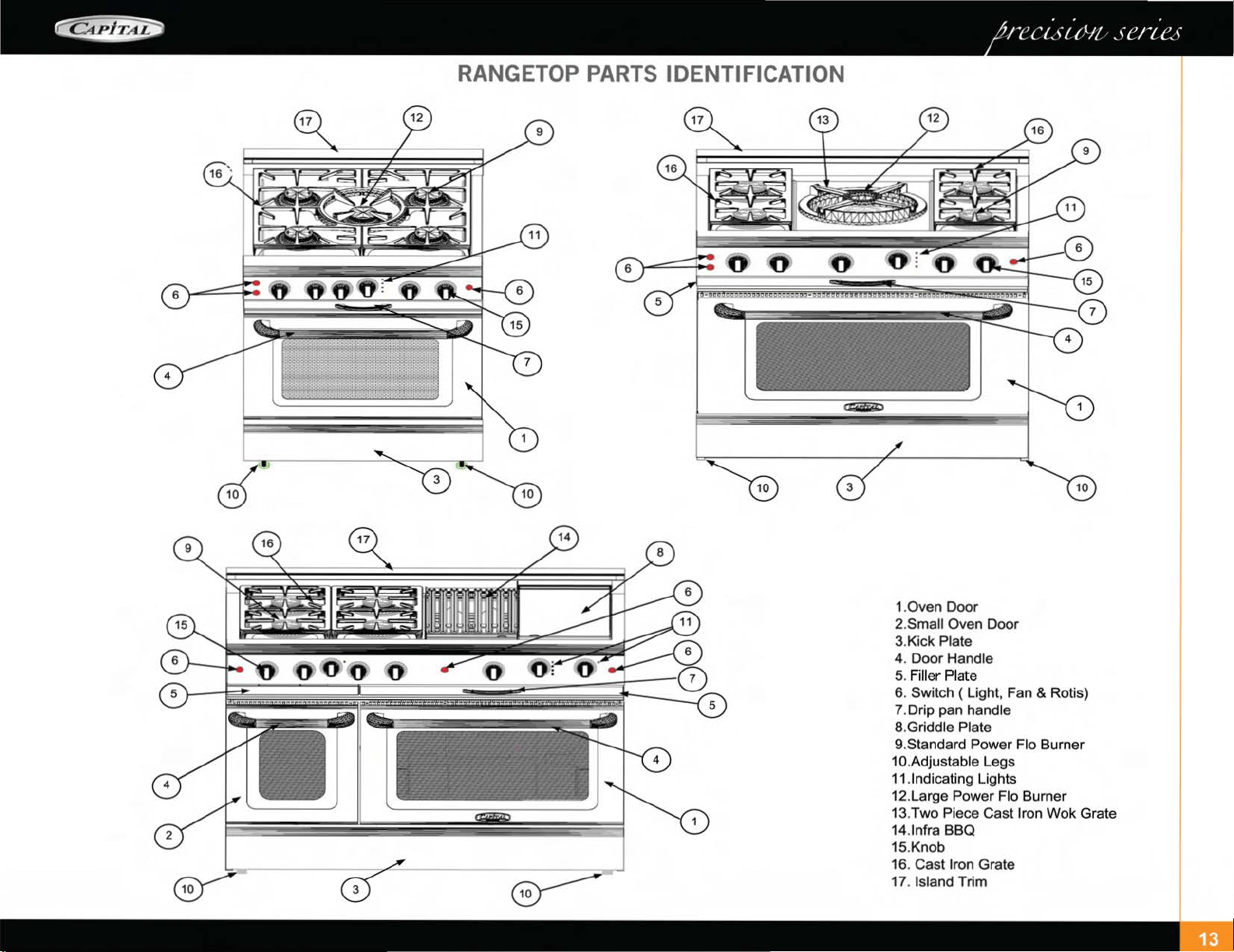
RANGETOP PARTS IDENTIFICATION
1.
0ven
Door
2.Small Oven Door
3.Kick Plate
4. Door Handle
5.
Fill
er
Plate
6. Switch ( Light, Fan & Rotis)
?.Drip pan handle
8.Griddle Plate
9.Standard Power Flo Burner
1
0 .Adjustable Legs
11
.1ndicating Lights
12.Large Power Flo Burner
13.Two Piece Cast
Iron Wok Grate
14.
1nfra
BBQ
15.Knob
16. Cast
Iron Grate
17.
Island Trim
U S I N G T H E R A N G E - T 0 P I P 0 W E R - F L 0
TM
B U R N E R S
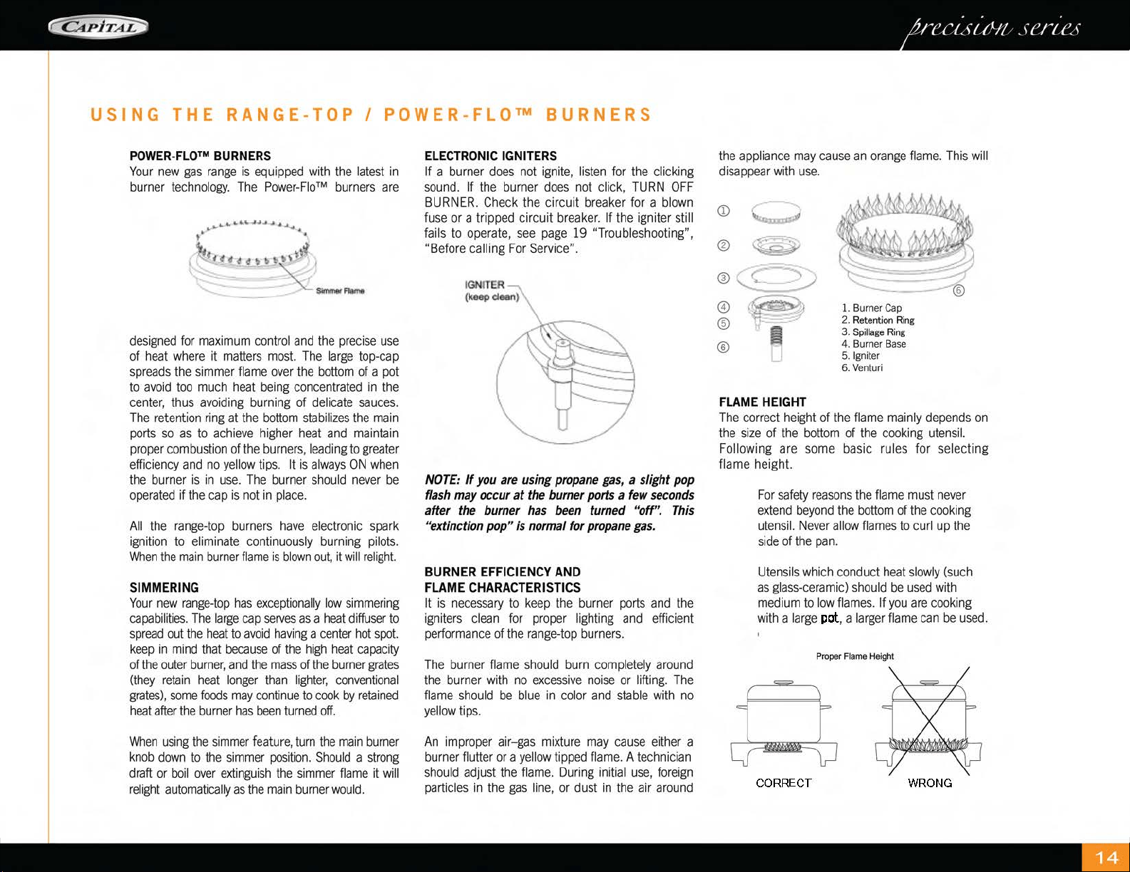
POWER-FLO™
BURNERS
Your
new
gas
range
is
equ
i
pped
with
the
l
atest
in
burner
technology.
The
Power-F
l
o™
b
urn
ers
are
_.,...,..,..
.....................
....,
..
......,.
t •
•
tt.H_t<
¢II
!»t'·~~
l
designed
for
max
imum
co
nt
ro
l
and
the
precise
use
of
heat
where
it
matters
most.
The
large
top-cap
spreads
the
simmer
flame
over
the
bottom
of a
pot
to
avoid
too
much
heat
be
in
g
concentrated
in
the
center,
thus
avoiding
burning
of
de
li
cate
sauces.
The
retention ri
ng
at
the
bottom
stabilizes
the
main
ports
so
as
to
ac
hi
eve
hi
gh
er
heat
and
maintain
proper
combustion
of
the
burners
,
leading
to
greater
efficiency
and
no
yellow
ti
ps.
It
is
al
ways
ON
when
the
b
urn
er
is
in
use.
Th
e
burner
shou
ld
never
be
operated
if
the
cap
is
not
in
place.
All
the
range
-
top
burners
have
electronic
spark
ignition
to
eliminate
continuously
burning
pilots.
When
the
ma
in
burner
fl
ame
is
blown
out,
it wi
ll
re
li
ght.
SIMMERING
Your
new
range-top
h
as
exceptionally
low
simmer
i
ng
capabil
iti
es.
The
large
cap
serves
as
a
heat
di
ffuser
to
spread
out
the
heat
to
avoid
having
a
center
ho
t
spot.
keep
in
mind
that
because
of
the h
igh
h
eat
capac
i
ty
of
the
ou
ter
bu
rner,
and
the
mass
of
the
bu
rner
grates
(they
retain
heat
longer
th
an
lig
ht
er,
conventional
grates),
some
foods
may
con
t
inue
to
cook
by
retained
heat
after
the
burner
has
bee
n
turned
off.
When
using
the
si
mme
r
feature,
turn
the
ma
in
burner
kn
ob
down
to
the
simmer
posit
i
on.
Shou
ld a
strong
draft
or
bo
il
over
extinguish
the
si
mmer
flame
it
will
relight
automat
i
cally
as
the
main
burner
would.
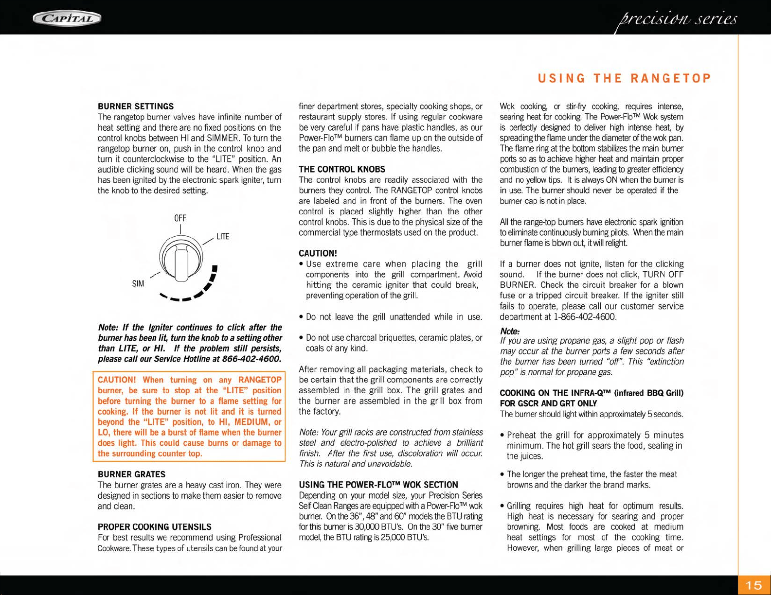
ELECTRONIC
IGNITERS
If a
burner
does
n
ot
ignite,
listen
for
the
clicking
sound.
If
the
burner
does
n
ot
click, T
URN
O
FF
BURNER.
Ch
eck
the
cir
cu
it
breaker
for
a
blown
fuse
or a tr
ipped
circuit
breaker.
If
the
i
gn
i
te
r sti
ll
fai
ls
to
operate,
see
page
19
"Trou
bleshoot
ing" ,
"Before
call
i
ng
For
Service".
NOTE:
If
you
are
using
propane
gas
, a
slight
pop
flash
may
occur
at
the
burner
ports
a
few
seconds
after
the
burner
has
been
turned
"off".
This
"extinction
pop"
is
normal
for
propane
gas.
BURNER
EFFICIENCY
AND
FLAME
CHARACTERISTICS
It
is
n
ecessary
to
keep
th
e
burner
ports
and
the
igniters
clean
for
proper
li
g
htin
g
and
efficient
performance
of
the
range-
t
op
burners.
The
burner
flame
should
burn
completely
around
the
burne
r
with
no
excessive
noise
or
lifting.
The
flame
sho
ul
d
be
b
lu
e
in
co
l
or
and
stable
with
no
yellow
tips.
An
improper
air-gas
mixture
may
cause
either
a
burner
flu
tt
er
or
a
yellow
tipp
ed
flame.
A t
echnician
should
ad
ju
st
the
fl
ame.
D
urin
g initial
use,
foreign
particles
in
the
gas
line,
or
dust
in
t
he
a
ir
around
the
appliance
may
cause
an
orange
fl
ame.
This
w
ill
di
sappea
r
with
u
se.
®
~
®
~Q)
@
-~
® tl
1.
Bu
rn
er
Ca
p
2. Retention
Ring
®
3.
Sp
ill
age
Ring
4. Bu
rner
Base
5.1g
niter
6.
Vent
uri
FLAME
HEIGHT
Th
e
co
rrect
height
of
the
flame
mainly
depends
on
the
si
ze
of
the
bottom
of
the
cooking
utensil.
Following are
some
basic
ru
les
for selecting
flame height.
For
safety
reasons
the
flame
must
never
extend
beyond
the
bottom
of
the
cooking
utensil.
Never
allow
flames
to
curl
up
the
s
id
e of
the
pan.
Utensils
which
conduct
heat
slowly
(such
as
glass-ceramic)
should
be
used
with
medium
to
low
flames.
If
you
are
cooking
with
a
large
pat, a
larger
flame
can
be
used.
Proper
Flame
Height
CORRECT
WRONG
BURNER
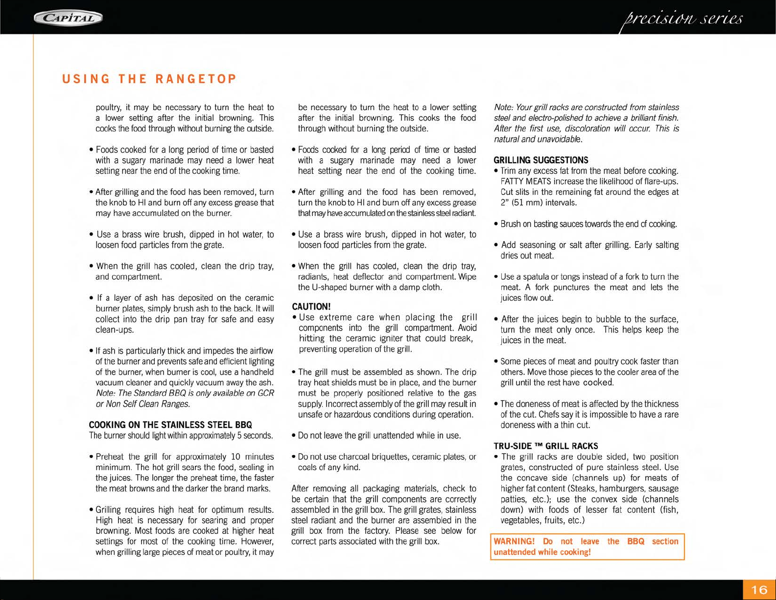
SETIINGS
The
rangetop
burner
va
l
ves
have
infin
i
te
number
of
heat
se
ttin
g
and
there
are
no
fixed
positions
on
the
control
knobs
between
HI
and
SIMMER.
To
turn
the
rangetop
bu
rner
on,
push
in
the
control
knob
and
turn
it
counterclockwise
to
the
"
LITE"
position.
An
audible
clicking
so
un
d
will
be
heard.
When
the
gas
has
bee
n
ignited
by
the
electronic
spark
igniter, turn
the
knob
to
the
desired
setting.
OFF
SIM
~LITE
/\l_j}
:
,
......
_
...
;
Note:
If
the Igniter continues
to
click after the
burner
has
been
lit
, turn the knob to a setting other
than LITE, or HI.
If
the
problem
still
persists,
please
call our Service Hotline
at
866-402-4600.
CAUTION!
When
turning
on
any
RANGETOP
burner,
be
sure
to
stop
at the "LITE" position
before
turning the
burner
to a
flame
setting for
cooking.
If the burner
is
not
lit
and
it
is
turned
beyond
the "LITE" position, to HI,
MEDIUM,
or
LO,
there
will
be
a burst of
flame
when
the burner
does
light.
This
could
cause
burns
or
damage
to
the
surrounding
counter top.
BURNER
GRATES
The
burner
grates
are
a
heavy
cast
ir
on.
They
were
designed
in
sect
i
ons
to
make
them
eas
i
er
to
remove
and
clean.
PROPER
COOKING
UTENSILS
F
or
best
results
we
recommend
using
Professional
Cookware.
These
types
of
utens
ils
can
be
found
at
your
f
in
er
department
stores,
specialty
cooking
shops,
or
restaurant
supply
sto
r
es.
If
using
r
eg
ul
ar
cookware
be
very
careful
if
pans
have
pl
ast
ic
hand
l
es,
as
our
Power-F
l
o™
burners
can
flame
up
on
the
outside
of
the
pan
and
me
lt
or
bubb
le
the
hand
l
es.
THE
CONTROL
KNOBS
Th
e
cont
rol
knobs
are
readily
associated
with
the
burners
they
co
n
trol.
The
RANGETOP
control
knobs
are
labeled
and
in
front
of
the
burners.
The
oven
contro
l
is
pl
aced
slightly
hi
gh
er
than
the
other
contro
l
knobs.
T
hi
s is due to t
he
physical
size
of
the
commerc
ial
type
thermostats
used
on
the
product.
CAUTION!
•
Use
extreme care when placing the grill
components
into
the
gri
ll
compartment.
Avoid
hitt
ing the
ceram
ic igniter that could
break,
preventing
operation
of
the
grill.
•
Do
not
leave
the g
rill
un
atte
n
ded
while
in
use.
•
Do
not
use
cha
r
coa
l b
ri
qu
ettes,
ceram
ic
plates,
or
coals
of
any
kind.
Afte
r removing
al
l packaging material
s,
check to
be
certain that the grill components are correctly
assemb
l
ed
in
the
grill
bo
x.
The
grill grates and
the burner
are
assemb
l
ed
in t
he
grill
box
from
the factory.
Note:
Your
grill
racks
are
constructed
from
stainless
steel
and
electro-polished
to
achieve
a brilliant
finish
. After
the
first
use,
discoloration
will
occur.
This
is
natural
and
unavoidable.
USING
THE
POWER-FLO™
WOK
SECTION
Depend
i
ng
on
your
model
si
ze,
your
Precision
Ser
i
es
Self
Clean
Ranges
are
eq
ui
pped
wi
th a
Power-F
l
o™
wok
burner.
On
the
36",
48"
and
60"
mode
ls the
BT
U
rat
i
ng
for
this
burner
is
30,CXX)
BTU's.
On
t
he
30"
five
burner
model,
the
BTU
rati
ng is
25,CXX)
BTU's.
USING
THE
RANGETOP
Wok
cook
i
ng,
or
stir-fry
cooking,
requires
intense,
seari
ng
heat
for
cook
i
ng.
The
Power-F
l
o™
Wok
system
is
perfectly
des
i
gned
to
deliver
hi
gh
intense
heat,
by
spreading
the
flame
under
the
di
ameter
of the
wok
pan.
The
flame
ring
at
the
bottom
stabi
l
izes
the
ma
in
burner
ports
so
as
to
achieve
h
ig
h
er
heat
and
maintai
n
prope
r
combustion
of
the
burners,
l
eading
to
greater
efficiency
and
no
yellow
tips.
It
is
always
ON
whe
n
the
burner
is
in
use.
The
burner
should
never
be
operated
if
the
burner
cap
is
not
in
place.
All
the
r
ange-top
burne
rs
have
elect
r
on
ic
spark
ig
n
itio
n
to
eliminate
cont
i
nuously
burning
pilots.
When
the
main
burne
r
flame
is
blown
out,
it
will
rel
i
ght.
If a burner
does
no
t
ign
i
te
, l
iste
n
for
the c
li
cking
sound.
If
the
burner
does
not
click,
TURN
OFF
BURNER.
Ch
eck
the
circuit
breaker
for a
blow
n
fuse
or
a tripped circuit
breaker.
If
the
ign
i
ter
sti
ll
fails
to
operate,
please
ca
ll
our
customer
service
departmen
t at 1-866-402-4600.
Note
:
If
you
are
using
propane
gas,
a slight
pop
or
flash
may
occur at
the
burner
ports
a
few
seconds
after
the
burner
has
been
turned
"off".
This
"extinction
pop"
is
normal
for
propane
gas.
COOKING
ON
THE
INFRA-Q™
(infrared
BBQ
Grill)
FOR
GSCR
AND
GRT
ONLY
T
he
burner
should
li
ght
wit
h
in
approximately
5
seconds
.
•
Preheat
the grill for approximately 5 minutes
m
in
imum.
The
hot
g
ri
ll
sears
th
e
food,
sealing
in
the
juices.
•
The
longer
the
preheat
time,
the
faster
the
meat
browns
and
the
darker
the
brand
marks.
•
Gr
i
ll
i
ng
requ
i
res
h
ig
h
heat
for
optimum
resu
l
ts.
High
heat
is
necessary
for
searing
and
proper
brown
i
ng.
Most
foods
are
cooked
at
med
iu
m
heat
settings
for
most
of
the
cooking
time.
However,
when
gr
illing lar
ge
pieces
of
meat
or
USING
THE
RANGETOP
po
ult
ry,
it
may
be
n
ecessary
to
turn
the
heat
to
a
lower
setting
after
the
initial
browning.
Th
is
coo
ks the
food
through
w
it
hout
burning
t
he
ou
t
side.
•
Foods
cooked
f
or
a
long
period
of
tim
e or
basted
w
ith
a su
gary
marinade
may
n
eed
a l
owe
r h
eat
se
ttin
g n
ear
th
e end of
th
e
coo
kin
g
tim
e.
•
After
grilling
and
the
food
has
been
removed,
turn
the
knob
to
HI
and
burn
off
any
excess
grease
that
may
ha
ve
accumulated
on
th
e b
urn
er.
•
Use
a
brass
wire
brush,
dipped
in
hot
wate
r,
to
l
oose
n
food
particles
from
the
grate.
•
When
the grill h
as
cooled,
cl
ean
the
drip
tray,
and
compartme
nt.
• If a
lay
er of
ash
h
as
deposited
on
the
ce
rami
c
burner
plates,
simply
brush
as
h
to
the
back.
It
will
collect
in
to
the drip
pan
tray
for
safe
and
easy
cl
ean-ups.
• If
ash
is
particularly
thick
and
impedes
the
airflow
of
the
burne
r
and
prevents
safe
and
efficient
lighting
of
the
burne
r,
when
burner
is
cool,
use
a
handheld
vac
u
um
cleane
r
and
quickly
vacuum
away
the
ash.
Note:
The
Standard
BBQ
is
only
available
on
GCR
or
Non
Self
Clean
Ranges.
C
OOKIN
G
ON
THE
S
TAINLE
SS
S
TEEL
BBQ
The
burner
should
l
ight
wi
thin
approxi
m
ately
5
seconds.
•
Pre
h
eat
the grill
for
approximately
10
minutes
minimum.
The
ho
t g
rill
sears
th
e
food,
sealing
in
the
juices.
The
longer
the
preheat
time,
the
faste
r
the
meat
browns
and
the
dar
k
er
the
brand
marks.
•
Gr
illing
requires
hi
gh h
ea
t
fo
r
opt
imum
results.
High
heat
is
necessary
for
sear
in
g
and
pr
ope
r
browning.
Most
f
oods
are
cooked
at
hi
gh
er
heat
sett
in
gs
for
most
of
the
cooking
t
im
e.
H
owever,
when
g
rillin
g
large
pieces
of
mea
t or
po
ul
try,
it
may
be
n
ecessary
to
turn
the
h
eat
to
a
lower
setting
after
the
initi
al
browning.
This
cooks
the
food
through
without burning
the
outside.
•
Foods
cooked
for
a
long
pe
r
iod
of t
ime
or
basted
with
a su
gary
marinade
may
need
a
lower
heat
setting
near
t
he
end of the
cooking
time.
•
After
grilling
and
the
food
has
been
removed,
turn
the
knob
to
HI
and
b
urn
off
any
excess
grease
that
may
h
ave
acc
umul
ated
on
th
e
stainless
steel
radiant
•
Use
a
brass
w
ir
e
brush,
dipped
in
hot
wate
r,
to
loosen
food
particles
from
the g
ra
te.
•
When
the
g
ri
ll
has
cooled,
clean
the drip
tray,
radiants,
heat
deflec
t
or
and
compartment.
Wipe
the
U-shaped
burner
with
a
damp
cloth.
CAUTION
!
•
Use
extreme
ca
re
when placing the grill
compo
n
ents
i
nto
the
g
ri
ll
compartment.
Avoid
hitti
ng
the
ce
ramic i
gn
iter
tha
t cou
ld
break,
pr
eve
ntin
g
ope
r
at
ion of
the
gr
il
l.
•
The
g
rill
must
be
assembled
as
sh
ow
n.
The
drip
tray
h
eat
s
hi
el
ds
must
be
in
pl
ace,
and
the
burner
must
be
properly
positioned
relative
to
the
gas
supply.
In
co
rr
ec
t
assemb
ly
of the grill
may
result
in
unsafe
or
hazardous
cond
itions during
operation.
•
Do
not
leave
the
grill
unattended
while
in
use.
• Do
not
use
charcoal
briquettes,
ceramic
plates,
or
coals
of
any
kind.
After
removing
a
ll
packaging
materials,
check
to
be
certa
in
that
the
grill
components
are
correctly
assembled
in
the grill
box.
T
he
g
rill
grates,
stainless
steel
radiant
and
the
b
urn
er are
assembled
in
the
grill
box
from
the
factory.
P
lease
see
below
for
correct
parts
associated
with
the
grill
box.
Note:
Your
grill
racks
are
constructed
from
stainless
steel
and
electro
-
polished
to
achieve
a
brilliant
finish.
After
the
first
use,
discoloration
will
occur.
This
is
natural
and
unavoidable.
GRILLIN
G SUG
GE
S
TI
ONS
•
Tr
im
any
excess
fa
t fr
om
th
e
meat
before
coo
king
.
FATTY
MEATS
in
cr
ease
the
like
lih
ood
of
flare-ups.
Cut
slits
in
the
remaining
fat
aro
un
d
th
e
edges
at
2"
(51
mm)
intervals.
•
Brush
on
bast
i
ng
sauces
towards
the
end
of
cooki
n
g.
•
Add
seaso
nin
g
or
salt
after
grilling.
Early
sa
ltin
g
dries
out
meat.
•
Use
a
spatula
or t
ongs
in
stead
of a
fork
to
turn
the
meat.
A
fork
punctures
the
meat
and
l
ets
the
juices
flow
out.
• Aft
er
th
e jui
ces
begin
to
bubble
to
the
surface,
turn
the
meat
only
once.
This
helps
keep
the
juices
in
the
meat.
•
Some
pieces
of
mea
t
and
po
ul
try
cook
faster
than
others.
Move
those
pi
eces
to
the
cooler
area
of
the
grill until
the
rest
have
cooked.
•
The
doneness
of
meat
is
affected
by
th
e
thickness
of
the
c
ut.
Chefs
say
it is
impossible
to
have
a
rare
doneness
with
a
thin
cut.
TRU
-S
IDE
™ G
RILL
RA
CKS
•
The grill
racks
are
double si
ded,
two
position
grates,
constructed of
pure
s
ta
in
l
ess
steel.
Use
the
co
n
cave
side
(channels up)
fo
r
meats
of
higher fat
con
tent
(Stea
k
s,
hamburgers,
sausage
patties,
etc.);
use
the
co
n
ve
x si
de
(chan
n
els
down)
with
foods
of l
esser
fat content
(f
i
sh,
vegetables,
fr
uits,
etc.)
WARNING!
Do
not
leave
the
BBQ
section
unattended
while
cooking!
HANDLING
EXCESSIVE
FLARE-UPS
•
The
intense
heat
needed
for grilling
may
also
cause
fiare-ups,
due
to
grease
and
basting
sauces
dripping
on
the
ceramic
burner
plates.
•
If
flare-ups
occur,
use
a
long
handled
spatula
to
move
the
food
to
another
area
of
the grill.
•
Should
flare-ups
become
excessive,
remove
the
food
from
the grill
and
turn off the
burner
•
Excessive
flames
occur
when
cooking
meat
with
high
fat
concentration,
i.e.
30%
ground
beef,
untrimmed
steaks,
lamb
chops,
etc.
•
Be
cautious
when
turning
meat
over,
and
never
PLOP
the
meat
on
the
grates.
COOKING
ON
THE
THERMO-GRIDD
L
E'M
Description:
•
The
built
in
griddle
is
made
of
non rusting
3/8" thick
stainless
steel.
This
produces
a
surface
that
is
easy
to
clean
.
•
T
he
griddle
has
a
aluminzed
steel
straight
tube
burner
that
is
lit
by
a
hot
surface
igniter.
The
griddle
should
pre
heat
for five to ten
minutes.
• A
chopping
block
is
available
as
an
accessory
and
purchased
separately.
It
is
sized
to
fit
on
top
of
the
griddle
surface
when
griddle
is
not
in
use.
•
The
burner
is
rated
at
18,000
BTU/HR.
CONTROL
KNOB
•
The
griddle
is
electronically
controlled
with
temperatures
marked
on
the
knob
from
150
degrees
F to
500
degrees
F
•
There
are
no
fixed
settings
on
the
knob
.
USING
THE
RANGETOP
/USING
YOUR
OVEN
•
Press
and
turn the
knob
counter-clockwise
to the
temperature setting.
PREPARING
THE
GRIDDLE
•
The
griddle
must
be
level
or
tilted
slightly
forward
for
optimum
performance.
The
griddle
should
have
been
leveled
during
installation
.
•
PRIOR
TO
USE,
It
is
NECESSARY
to
wash
the
griddle
plate
with
warm
soapy
water
then
rinsed
with
clear
water.
The
griddle
may
be
used
without
butter,
margarine,
or
oil.
Hov.€ver,
a
very
small
amount
may
be
used
to
flavor
foods.
COOK
I
NG
ON
T
HE
GRIDD
LE
•
Check
that the
grease
tray
is
tucked
under
the
griddle
plate
overhang.
•
Turn
the
knob
to
the
cooking
temperature
to
preheat
the
griddle
.
•
Preheat
5-10
Minutes.
•
Add
butter,
margarine,
shortening
or
oil
for
more
flavor:
Add
food
and
cook!
OVE
N
USE
GEN
E
RAL
(O
nl
y
on
lar
ge
se
lf
clea
n
oven)
Your
large
new
oven
can
be
used
in
6
cooking
mode
l
s;
convection
bake,
regular
bake,
convection
broil,
regular
broil,
convection-broil
rotisserie,
regular
-
broil
rotisserie.
To
help
you
decide
which
way
to
cook
your
food
read
this
information
first.
Remember
this
is
a
new
oven
and
t
he
thermostat
has
been
checked
for
accuracy.
Your
old
oven
had
a thermostat that
over
the
years
got a little
cold.
Check
your
recipes
for
the
correct
time
and
temperature
and
don't
use
the
old
time
or
temperature
you
were
using
to
compensate
for
your
old
oven
being
off
temperature
.
SMA
LL
OVEN REGU
LAR
B
AK
E ONLY
BURNERS
Your
new
Precision
SeriesTM
range
is
equipped
with
bake
and
broil burners typical
of
those
used
in
restaurants.
The
oven
broiler burner
is
18,000 Btu/hr
and
the
oven
baking burner
is
30,000 Btu/hr.
ELECTRIC
GLOW
IGNITER
The
oven
bake
and
broil
burners
are
equipped
with
an
electric
glow
igniter
and
safety
system
which
lights the
gas
.
There
will
be
a
delay
after
the
control
knob
has
been
turned
on
to
when
you
actually
hear
gas
arrive
at the
burner.
The
burner
will
ignite after
the
gas
reaches
the
burner,
sometimes
this
can
take
as
long
as
45
seconds
.
USING
CONVECTION
BAKE
AND
REGULAR
BAKE
TO
SE
T
TH
E
OVEN
FOR
CONVECTION
BAK
E
AND
REGU
L
AR
BAKE
Decide
if
)W
are
gjng
to
use
CONVECTION
BAKE
a-
REGULAR
BAK
E.
These
ccd<ing
mcxles
are
for
baking
a-
v.arming:
using
one,
t.v..o,
three
a-
four
racks.
Jf
)W
are
gjng
to
use
Regular
Bake
tum
the
o.e1
contrd
knob
to
the
temperature
used
in
the
recipe.
To
use
Convectioo
Bake,
simply
press
the
CONVECTION
Button
located
on
the front
panel
to start the
Convection
Fan.
CONDENSATION
During
any
cooking
process
there
is
a
certain
amount
of
moisture
that
evaporates
from
the
food.
The
amount
of
moisture
that
condenses
on
the
oven
depends
on
the
moisture
content
of the
food.
The
moisture
will
condense
on
any
surface
that
is
cooler
than
the
inside
of
the
oven,
such
as
the
control
panel
or
the
top
of
the
door.
CONVECTION
BAKE
Convection
Bake
is
baking
with
a
fan
at
the
back
ri
the
oven
circulating
the
hot
air
in
a
continuous
pattern
around
the
food.
This
circulating
hot
air
heats
and
biUM'Is
the
surface
ri
the
food
more
effectively
than
in
a
standard
oven.
This
aiiCMS
most
foods
to
be
cooked
at
lov.er
oven
temperature
or
in
less
time,
USING
YOUR
OVEN
if
baked
at
the r
egula
r
tempe
r
ature
.
Th
e
air
is
re
-
ci
rcu
lat
ed
and
r
eheated.
Uncovered,
l
onge
r
cooki
ng
foods
su
ch
as
l
arge
pi
eces
of
meat
or
othe
r
foods
th
at
can
be
cooke
d in l
ow
sided
ba
king
utensils
or
air l
eavened
foods,
are
where
yo
u
will
see
the
mos
t
savings
in
cook
in
g t
ime.
Using
mult
iple
r
ack
at the
same
t
ime
wi
ll
ac
hi
eve
a
good
ti
me
savi
n
g,
as
yo
u
can
cook
more
food
at
th
e
same
ti
m
e.
Th
e n
umbe
r
of r
ecipes
r
equi
ri
ng
pre
h
eati
ng of t
he
ove
n
is
r
educed
consi
der
ably
because
t
he
h
eat
reac
hes
th
e
food
fas
te
r
as
the
h
ot
air cir
culates
aro
u
nd
the
food.
FOOD
S
SUITABLE
FOR
CONVECTION
BAKE
Air L
eavened
Foods
(angel
food
cake,
so
uffl
es,
cr
ea
m pu
ffs,
me
rin
gue she
ll
s)
Appet
iz
ers
Br
eads
Ma
in
Dish
es
Ove
n
Mea
ls
(1
to
4 r
ac
k
s)
Coo
ki
es
Pi
es
Po
ul
try
Roasts
CONVERTING
RECIPES
TO
CONVECTION
BAKE
Low
sided
baking
utensils
w
ill
provide
the
best
r
es
ult
s,
as
the hot air
can
reach
all
sides
of
th
e u
te
ns
il
easier.
The
oven
te
m
pe
rature
can
be
left
the
sa
me
as
th
e
r
ec
i
pe
and
the
foo
d
coo
ked a shorter
perio
d of
tim
e.
Th
e tem
pe
rature
ca
n
be
lowered
25°F
to
50°F
and
the
foo
d will
probably
take
the
same
length
of
tim
e
to
coo
k
as
th
e r
ec
i
pe
stat
es.
If
yo
u f
in
d
th
at
food
is
ade
qu
ate
ly br
ow
n
ed
on
th
e o
ut
si
de,
b
ut
not
do
ne
in
the
center,
l
owe
r the
temperature
another
25°F and
add
to
baking
t
im
e.
When
reducing
the
te
mp
era
ture
al
ways
ch
ec
k
the
food
for
doneness,
a
minu
te or
two
be
f
or
e
the
minimum
time
state
d
in
the
r
ec
i
pe,
as
tim
e
can
always
be
added.
Some
r
ec
i
pes
w
ill
coo
k
faster
than
others.
Th
e
re
is
no
w
ay
to
pr
ed
ict
ex
ac
tl
y
how
long
each
r
ec
i
pe
will
take
wh
en
yo
u
co
n
ve
rt
it
to
co
n
vect
ion.
Co
n
vect
ion w
ill
be
easier
to
use
after
you
ha
ve
u
sed
it a
fe
w
times
as
yo
u w
ill
begin
to
un
de
rstand the
way
it
bakes
.
SELECTING
UTEN
S
ILS
FOR
CONVECTION
BAKE
Cooking
by
co
n
vec
ti
on
does
n
ot
require
any
spec
ia
ll
y
designed
baking
u
te
ns
il
s.
You
p
roba
b
ly
h
ave
man
y
utensils
in
yo
ur
kitchen
that
are
suitable
to
u
se.
Wh
en
choosing
a
baking
u
te
nsil,
co
nsi
de
r
the
mater
ial,
the
size
and
s
ha
pe
as
th
ey
all
affect
th
e
baking
time,
the
appearance
of
the
finished
pro
d
uct.
M
etal
bake
war
e
(aluminum,
st
eel
and
cast
i
ro
n) all
result
in
the
fas
t
es
t
coo
kin
g
time
and
the
bes
t
end
product.
Aluminum pans w
ork
best
fo
r
all
types
of
baked
goods.
For
th
e
bes
t
browning,
use
a
pan
with
a dark or
d
ull
finish
that
ab
sorbs
hea
t,
wh
en
baking
pies
and
breads.
A s
hin
y fi
nish
works
best
for
cakes
and
cookies,
s
in
ce
it re
flects
so
me of
the
he
at
an
d
provides
a ten
dere
r
surface.
Coo
ki
e
sheets
with
only
one
lip will
give
the
best
results,
as
the h
eated
air
can
circulate
all
around
the
si
d
es
of the
foo
d.
F
or
roast
i
ng,
use
bo
tt
om
of t
he
bro
il
pa
n
an
d
ele
v
ate
t
he
meat
on a
meta
l r
oasti
ng
rac
k.
Glass-cera
m
ic
or
gl
a
ss
utensil
s do n
ot
con
du
ct
heat
as
well
as
meta
l, but th
ey
can
be
used.
U
se
the
m
fo
r
foods
th
at
do
n
ot
requi
re a
dark
b
rown
crust or cr
is
pin
g,
such
as
so
u
ffles.
B
aked
i
te
ms
cook
mo
re q
ui
ckly
an
d
eve
nl
y ifthey
are
in
di
v
id
u
all
y sma
ll
er
in
size
,
i.e
.
two
or
thr
ee
sm
all
foods
do
be
tt
er
than
one
la
rge
p
iece.
When
si
n
gle
f
ood
items
are
baked,
al
ways
cen
t
er
t
he
rack.
If
severa
l
foods
are
being
baked
,
space
them
evenly
on t
he
racks.
RACK
POSITIONS
One
to
fou
r
racks
c
an
be
us
ed
simultaneously
during
convection
baking.
Place
the
rac
k
(s)
in
the
desire
d
pos
iti
on
before
t
urnin
g
the
ove
n
on.
Sto
re
the
unused
racks
out
of
the
oven.
Rack
pos
ition 2
(second
fro
m
bo
tt
om)
will pr
obab
ly
be
used
the
most
for
single
rack
convection
baking
.
W
hen
baking
on
more
t
han
one
rack
you
do
not
need
to
stagger
th
e
pans.
A
llow
at
least
1" of
space
be
tw
een
the
oven
wa
ll
s
an
d
th
e
pans
so the
heated
air
can
circulate.
Pans
sho
ul
d
be
placed
in
the
cen
te
r of the
ov
e
n,
stac
ked
ab
ov
e
ea
ch
ra
c
k.
REGULAR
BAKE
B
ake
is
baking
with
hot convected
air;
there
is
no
fan.
The
air
moveme
nt
com
es f
rom
natura
l
convect
i
on
as
the
air
heats,
it m
oves
to
the t
op
of
th
e
ove
n.
T
hi
s
oven
mode
is
the
same
as
you
h
ave
bee
n
using
f
or
b
akin
g
on
one
or
tw
o
racks.
FOODS
SUITABLE
FOR
BAKE
A
ppet
iz
e
rs
P
ies,
Cakes
B
reads
D
esserts
M
ain
Dishes
Oven
M
eals
(1
to
2
racks)
P
oul
t
ry
R
oas
ts
CAUTION:
Aluminum foil
should
never
be
used
to
cover
the
oven
racks
or
to line the
oven
bottom.
The
trapped
heat
can
damage
the
porcelain
and
the
heated
air
cannot
adequately
reach
the
food
being
baked.
RACK
POSITIONS
O
ne
or
two
racks
can
be
u
sed
simultaneously
during
bake.
P
la
ce
the
rack(s)
in
the
desired
pos
iti
on
before
turning
the
oven
o
n.
S
tore
any
unu
sed
racks
ou
t of t
he
oven.
R
ack
position
2
(second
from
botto
m) w
ill
probabl
y
be
used
t
he
mos
t f
or
single
rack
baking.
If
you
are
us
i
ng
two
racks
sim
u
ltaneously,
be
sure
to
check
the
food
on t
he
bottom
rack
soo
n
er
th
an
the
mi
n
im
um
ti
m
e.
The
food
on
the
lo
wer r
ac
k
pos
i
tion
may
coo
k
slightly
faster
than
the
food
on
the
u
pper
rack,
partic
u
larly
if y
ou
a
re
using
la
r
ge
bak
i
ng
ut
en
si
ls
so
tha
t
one
is
not
di
rect
ly
above
t
he
ot
h
er
and the
heated
air
can
ci
rc
u
la
te fr
ee
ly
around
eac
h
pan.
Allow
at
least
one
inch
of
space
between
the
oven
walls
and
the
pans.
If u
si
ng
large
or
commerc
i
al
size
bak
i
ng
ut
en
si
l
s,
the
food
may
take
a
few
extra
mi
nu
t
es
as
the
ai
r
can
n
ot
ci
rc
u
la
te
as
f
reely
as
it
does
wit
h a
smalle
r
pa
n. Wh
en
using
comme
r
cial
si
ze
ba
k
ing
utens
i
ls,
use
on
ly
one
rack
as
the
heat
does
no
t
have
the r
oom
to
circulate.
GETTING
THE
BEST
RESULTS
BAKING:
•
Fo
ll
ow
t
he
recipe
amo
unt
and
ingredients,
i
nc
l
ud
i
ng
the
size
and sh
ape
of
the
ba
k
ing
utensil
r
ecomme
n
ded
in
the r
ec
i
pe.
•
Do
n
ot
open
t
he
oven
door
"ju
st
to
peek,"
u
se
t
he
in
te
ri
or
ove
n
li
ght and
look
through
the
window.
•
Do
n
ot
u
se
the
oven
for
storage,
especially
when
ba
kin
g
in
the
oven.
Extra
utensils,
not
being
used
fo
r b
akin
g,
c
an
affect
the
food
product,
baking
ti
me,
br
ow
nin
g,
and
end
result.
• If
yo
u are us
in
g gl
ass
u
te
ns
il
s,
l
owe
r the
tempe
ra
ture
25°F.
•
Use
a m
inu
te
ti
me
r and
set
it for
the
minimum
ti
me
su
ggested
in
the
recipe.
CONVECTION
BAKING
•
Fo
ll
ow
the first
three
recomme
n
dations
above.
•
Meta
l u
te
ns
il
s gi
ve
bette
r r
es
ul
ts,
in
co
n
vect
ion,
than
do
glass
baking
utensils.
If
you
use
glass,
it
usua
ll
y is n
ot
n
ecess
a
ry
to
l
owe
r the
temper
a
ture
an
additional
25°F.
•
Use
a m
inu
te
ti
mer
and
set
it for
less
than
m
ini
mum ti
me
su
ggested
in
the
recipe.
The
first
ti
me
yo
u u
se
a r
ec
i
pe
in
the
convection
mode,
be
s
ur
e
to
n
ote
the
new
baking
time
on
your
recipe
fo
r futu
re
refere
n
ce.
• Be
su
re
to
read
t
he
basic
in
format
ion
on
convection
before
usi
ng the
oven
for
the
first
time,
page
14-16
.
•
Keep
in
m
in
d
th
at
co
n
vec
t
ion
ba
kin
g
res
ults
vary,
depending
on
type
of
product.
Notes:
HIGH
ALTITUDE
BAKING
Rec
i
pes
and
baking
times
va
ry
if
yo
u
are
b
akin
g at
high
altitude.
F
or
accurate
information
w
ri
te
to the
Ag
ri
culture
Exte
nsion
Service.
Colorado
State
U
ni
vers
i
ty,
Fort
Co
llin
s,
Colorado
80521.
Spec
i
fy
the
type
of
in
fo
r
ma
ti
on
and
the
baking
mode
(convention
ba
ke
or
bake)
you
need,
i.
e.
ca
k
es,
breads,
etc.
There m
ay
be
a
cos
t for t
he
bulle
t
ins.
TO
USE
THE
OVEN
ON
LOW
TEMPERATURE
The
ove
n
can
be
u
sed
to
keep
ho
t
food
hot,
to
de
h
yd
rate
food,
to
wa
rm
pla
t
es,
for
sl
ow
coo
kin
g
(as
in
a
croc
k
pot),
and
to
defrost
foods.
Yo
u
ca
n k
eep
hot,
cooked
food
atservingtemperature.
Se
t t
he
oven
to
the
tempe
rature su
gges
t
ed
in
the
chart.
R
are
meat
must
be
eaten
when
it
is
removed
fr
om
the
oven,
as
it
cont
i
nues
cooki
ng
fr
om
i
ts
ow
n
heat.
To
k
eep
f
ood
moist,
it mu
st
be
covered
with
a
lu
m
inu
m
fo
il
or
a
li
d.
To
dehydrate
food,
follow
su
ggest
ions
in
a r
ec
i
pe.
To
warm
plates,
ch
ec
k w
ith
the
dishware
ma
nu
fac-
turer for
the
recommended
temperatures.
To u
se
t
he
oven
as
a
low
coo
k
er
se
t
the
oven
control
k
nob
to
255°F.
Pl
ace
the
food
in the
ove
n in a
pan
wi
th a
t
igh
t fitti
ng
l
id.
Follow
rec
i
pes
fo
r t
his
type
of
cooki
n
g.
To
th
aw
uncooked
frozen
f
ood,
set
the
ove
n
control
kn
ob
to "warm". Be
sure
th
e
food
is
tightly
wrapped
in
foil.
Th
aw
th
e
food
ju
st
en
ough.
Cook
i
mmed
i
ately
.
USING
YOUR
OVEN
Do
not
refreeze.
To
thaw
fr
oze
n
cooked
food,
set
the
oven
knob
to
170°
F.
Loose
n
th
e
freezer
wr
app
in
g.
Do
not
u
se
pl
ast
ic wr
ap
or
wax
paper
in
the
ove
n.
FOOD
SAFETY
According to the United
States
Department of
Agriculture
you
should
not
hold
foods
at
temperatures
between
40"F to 140"F for longer than 2
hours.
USING
CONVECTION
BROIL
AND
REGULAR
BROIL.
TO
SET
THE
OVEN
FOR
CONVECTION
BROIL
AND
REGULAR
BROIL
CAUTION:
Pay
special
attention
when
setting the
Oven
Control
Knob
on
"BROIL".
If
you
set
the
knob
past
the
"BROIL"
setting,
the
burner
will
not
ignite.
Dec
i
de
if
you
are
go
in
g to
use
REGULAR
BROIL
or
CONVECTION
BROIL.
If
yo
u
are
going
to
use
r
egular
broil
t
urn
the
Oven
Co
n
tro
l
knob
To
"BRO
I
L".
To
u
se
Convection
Broil turn the
Oven
Contro
l
Knob
to
"BROIL"
and
press
the
CONVECTION
button
to
operate
th
e
fan.
The
burne
r
will
ignite
after
the
gas
r
eaches
th
e
burner.
The
"oven
on" indicator
li
ght
will
come
on
to
let
you
know
that
the
broiler
is
currently
on.
Duri
ng
the broi
li
ng
process,
t
he
infr
a-red
burne
r
produces
such
an
in
te
n
se
h
eat
that the b
urn
er w
ill
cyc
le on and off
to
ma
inta
in
an efficient
yet
safe
inte
ri
or
cooking
environment.
The
HEATI
NG
indicator
li
ght
on
the
va
l
ve
pa
n
el
cycles
on
and
off
wi
th bu
rner
to l
et
t
he
user
k
now
wh
en
t
he
burner
is li
t.
T
his
cycl
i
ng
process
is
u
sed
to
evenly
dis
t
ribute
and
sa
f
ety
control
t
he
i
ntense
heat
that
t
he
bro
il bu
rner
pr
od
u
ces.
The
cycl
i
ng
featu
re
prevents
the
burner
from
pr
od
u
ci
ng
ra
n
ge-damag
i
ng
heat.
RACK
POSITION
The
rac
k
positio
n
depends
on the
type
and
thic
kn
ess
of
the
food.
T
hi
ck
pieces
of
meat
or
poultry
(1"
or
more)
wo
u
ld
typica
l
ly
be
br
oiled
or
convectio
n
broi
l
ed
on
rac
k
posi
ti
on
3.
St
eaks,
USING
YOUR
OVEN
chops
a
nd
h
amb
ur
gers
would
typica
ll
y
be
broiled
on
rack
pos
i
tio
n
4.
If t
op
brow
ni
ng
casseroles
or
bread,
the
th
i
ckness
of
the
food
would
i
ndicate
the
posi
ti
on.
Cassero
l
es
and
bread
would
typically
be
browned
on
rac
k
posit
i
on
2
(see
instructions
below
for
mo
re
in
forma
ti
on).
CONVECTION
BROIL
Co
nv
ect
ion
bro
il
is
cooking
by
intense
in
frar
ed
rad
i
ant
hea
t
supp
li
ed
by
the
broil
burner
while
fan
at
th
e
bac
k of the
oven
circulates
hot
air in a
cont
i
nuous
patte
rn
around
th
e
food.
Convection
bro
il
cooks
th
e
food
with
better
resu
l
ts
fo
r
th
icker c
ut
s of
meat.
The
meat
sears
on
the
o
ut
si
de
and
retains
more
jui
ces
a
nd
n
at
ur
al fl
avo
r
in
si
de
with l
ess
shrink
age.
FOODS
SUITABLE
FOR
CONVECTION
BROILING:
Thi
cke
r Cu
ts
of
Meat
(1" or
more)
Rac
k
pos
ition
#3
(same
pos
ition for
bro
ilin
g)
Thicker,
I
rregular-sized
Pieces
of
Poultry
(1" or
more)
Rack
pos
ition
#2
or
#3
(same
pos
ition for bro
ilin
g)
Th
icker,
Pieces
of
Fish
(1"
or
more)
Rack
pos
ition
#3
(same
pos
ition
fo
r
bro
ilin
g)
T
op
Browning:
Casseroles
and
Breads
Rac
k
pos
ition
#2
or
#3
(same
pos
ition
fo
r
bro
ilin
g)
REGULAR
BROIL
Broil
is
coo
king
by
in
ten
se
i
nfrared
radian
t
heat
suppl
i
ed
by
the
bro
il
b
urn
er l
ocated
at the
top
of the
ove
n.
FOODS
SUITABLE
FOR
BROILING:
Appet
i
ze
rs
Rack
pos
iti
on
#3
or
#4
Meats,
Po
ul
try,
Fish
(under 1 ")
Rack
pos
iti
on
#4
T
op
Browning:
Casseroles
and
breads
Rack
pos
ition
#2
or
#3
NOTE
:
The
broiler
pan
for
both
broiling and
convection
broiling
should
be
placed all
the
way
to
the
back
of
the
oven
and
centered
on
the
rack
for
best
results.
USING
A
MEAT
THERMOMETER
TO
BROIL
AND
CONVECTION
BROIL
To
accura
te
ly
determine
the
doneness
of a thick
steak
or
chop
(1-1/2)
inches
thick
or
more),
use
a
meat
thermometer.
I
nsert
t
he
po
int of
the
thermometer
into
the
side
of the
meat
to
the
center.
Cook
the
fi
rst
to
90°F f
or
rare
meat.
Coo
k
th
e fi
rst
si
de
100°F
for
medium
to
well
done.
Coo
k
the
second
side
to
the
desired
degree
for
th
e
doneness
you
want,
140°F
to
1
45°F
fo
r
rare,
and
1
50°F
to
155°F
fo
r
medium
and
160°F
to
165°F
for
well
do
n
e.
If
you
are
cooking
pork,
cook
to
160°F.
A
large
two-piece
broil
pan
comes
wi
th
your
new
range.
When
you
are
bro
ilin
g,
al
ways
use
both
pieces.
Do
not
cover
th
e
gr
id w
ith
a
lu
mi
num
fo
il.
This
slotted
gr
id a
ll
ows
the
grease
drippings
to
fl
ow
into
the
bottom
of
the
pan
keeping
it
away
from
the
in
t
ense
heat
of t
he
infra-red
bro
i
ler
bu
rner.
Th
is
helps
to
mi
nimize
the
smoki
ng
and
spatter
i
ng
of the
grease.
TO
GET
THE
BEST
RESULTS
OPEN
DOOR
BROILING
NOTE
:
Open
Door
Broiling is
also
possible with
the
Precision
Series
oven.
However,
the
oven
door
hinge
DOES
NOT
have
a dedicated
Broii-Stop_pqsition.
To
achieve
the best
results
for
Open-Door
Broiling,
open
oven
door
approximately 6-8 Inches.
WARNING!
NEVER
leave
pets
and/or
small
children
unattended
while
oven
is
in
the
Open
Door
Broiling
position.
Front
panel
and
knobs
may
get
hot
to the
touch
as
the
heat
is
directly
escaping
to the front
section
of the
oven.
Wear
oven
mitts
and
always
use
Caution!
NOTE
:
It
is not
recommended
to
use
the convection
fan
in
Open
Door
Broiling.
•
Defrost
the
food
before
starting
to
cook.
•
Put
food
on
broiler
pan,
center
and
push
broiler
pan
to
the
very
back
of
the
oven
rack.
•
Set
a min
ute
t
imer
for
the
mi
n
im
um t
ime
to
check
the
food.
•
Steaks
sh
ould
be
at
least
one
inch
th
ick,
if
rare
doneness
is
desired.
It
is
di
ffic
u
lt
to
get
rare
wi
th
meat
th
at
is
th
in
n
er.
•
After
half
the
total
cooki
ng
time,
turn
the
food
over
only
once.
It
is
not
necessary
to
turn
over
thin
foods
(fillet of
fish,
Ham
slices,
etc.).
Liver
slices
must
be
turned
over.
•
Use
a
two-piece
broil
pan.
Two-piece
broil
pans
are
designed
to
minimize
smoke
and
spatter
.
DO
NOT
cover
the
slotted
grid
with
aluminum
foil.
This
will
catch
the
grease
and
could
cause
a
fire.
•
When
t
op
browning
use
me
t
al
or
glass-ceramic
bake
ware.
DO
NOT
use
heat-proof
Glass
or
pottery
as
this
type
of
glassware
cannot
withstand
the
intense
heat
of
the
broiler
burner.
NOTE:
You
cannot
use
the
broiler burner and the
bake
burner
at
the
same
time.
When
one
is
on,
the
other cannot
be
turned on!
USING
THE
OVEN
ROTISSERIE
Your
Gas
Self
Clean
ove
n
co
n
tains
a
rotisserie
system,
complete
with
a
vertical
positio
n
ing
rod,
aU-bracket,
a
ho
r
izontal
sp
it
r
od,
and h
eavy-duty,
cast
stain
l
ess
s
te
el
prongs.
Al
so,
the
oven
comes
with
a
porcelain-coated,
two
pi
ece
bro
i
ler
pan, prov
i
ded
for
yo
ur
conven
i
ence.
Using
the
rotisserie
is
quite
simple.
•
Place
the
vertica
l
positioning
rod
into
the
hole
located
on
the
bottom
l
eft
si
de
of
the
ove
n
can.
• P
la
ce
your
rotisserie
spit-rod
w
ith
yo
ur
meat
pr
epa
r
ed
betwee
n
the
two
pron
gs
on
the
U-b
r
ac
k
et,
a
nd
sw
in
g
in
to
place
on
the
right
side
wa
ll
of the
ove
n
ca
n.
• P
lace
the
broil
pan
directly
beneath
the
meat.
•
Close
oven
door
•
Set
the
oven
to
Broil
mode
• P
ress
the
rotisserie
button
on
the
left
side
of
the
fro
nt
panel
wh
i
ch
will
act
i
vate
the
rotisserie
motor.
NOTE:
For
Convection
Rotisserie,
simply
follow
thP.
same
steps
and
first
press
the
rotisserie
button,
followed
by
the
convection
button
.
NOTE:
Rotisserie
system
is
only
available
in
the
Precisiot,
Series
gas
Seff-Ciean
Ranges
and
NOT
the
Precisiot,
Series
sfilndard
non-seff
clean
gas
convection
ranges.
NOTE:
Rotisserie
system
can
ONLY
be
used
in
thP.
Broil
Mode,
and
not
Bake
mode
.
INTERNAL
COOKING
TEMPERATURES
:
Egg
and
Egg
Dishes
Eggs
OVEN
TEMPERATURE
Cook
until
yolk
and
white
are
firm
Egg
Casseroles
160
degree
F
Egg
Sauces
,
Custards
160
degree
F
Ground
Meat
and
Meat
Mixtures
Turk
ey
,
Chicken
165
degree
F
Beef,
Veal,
Lamb,
Pork
160
degree
F
Fresh
Beef,
Veal,
Lamb
M
edium
R
are
M
edium
Well
Do
ne
Fresh
Pork
M
edium
Well
Do
ne
Roast
Beef
Cooked
Commercially
Vacuum
Sealed
145
degree
F
160
degree
F
170 D
egree
F
160
degree
F
170
degree
F
140
degree
F
140
degree
F
USING
YOUR
OVEN-
SELF
CLEAN
MODE
Ready
to
ea
t
Poultry
C
hi
cken, T
urkey-Whole
C
hi
cken,
Turkey-dark
meat
Po
ult
ry-breas
t
Duck and
Goose
Stuffing
1
40
degree
F
180
degree
F
180
degree
F
170
degree
F
180
degree
F
Coo
k
ed
alone
or
in
b
ir
d 165
degree
F
Sauces,
Soups,
Gravies,
Marinades
Used
with
raw
meat,
poultry,
or
fish
Bring
to
boil
Seafood
F
in
Fish
OVEN
SELF-CLEANING
Cook
u
nt
il
opaque
and
fla
k
es
easi
ly
wit
h a
fork
Th
e
se
lf-cl
ea
nin
g
ove
n of
your
new
range
features
pyrolytic
se
lf-cl
ea
nin
g.
When
set
in
the
SE
L
F-C
LE
AN
mode
, the
oven
reaches
a
high
temperature
that
burns
off
th
e
food
soil.
When
the
oven
is
on
fo
r
SELF
-
CLEAN,
only
the
RANGE
TO
P
burners
can
be
used.
NOTE
:
Before
turning
oven
to
self-clean
mode,
wipe
up
the
excessive
Food
Soil.
This
will
minimize
any
excessive
smoke
or
flames
that
may
occur.
It
is
common to
see
smo
ke and/or flames
duri
ng
the
SELF
-C
LEAN
cycle, depending
on
t
he
co
nte
nt and amount of
so
il r
ema
i
ni
ng
in
t
he
ove
n. If a fl
ame
pe
rsists, turn off the
oven
and
allow it
to
cool
before opening t
he
door
to
wipe
up the excessive
food
so
i
l.
At
the
end
of
the
SELF-CLEAN
cycle,
some
gray
ash
or
burned
residue
may
remain
inside
the
oven.
This
is a
mineral
deposit
that
does
not
burn
or
melt.
The
amo
unt
of
ash
depends
on
h
ow
hea
v
il
y
soiled
the
ove
n
was
before
the
oven
was
cl
ea
n
ed
. It
is
easily
removed,
once
th
e
oven
has
cooled,
using
a
damp
pape
r
towel,
spo
n
ge,
or
clo
th
.
Wipe
off any
smo
ke r
esidue
that
remains
on the
fron
t fr
ame
w
it
h
Form
u
la
409®
or
Fa
n
tas
ti
k®.
If
stain
remains,
use
a m
il
d liquid
cleanser
.
The
amou
nt
of
smo
ke
stain
is
di
rec
tl
y
related
to
the
amou
nt
of
food
so
il
left
in
the time of
se
l
f-clea
n
ing.
Clean
the
oven
often.
OVEN
DOOR
LOCK
DURING
SELF-CLEAN
When
the
cl
ea
n
cycle
starts,
the
lock
li
g
ht
turns
on,
a
nd
the
automatic
doo
r lock
cyc
le
begins.
Do
not
attempt
to
open
the
door
when
the
lock
li
g
ht
is o
n.
You
can
stop
the
cycle
by
turning
to
OFF
pos
iti
on.
Th
e lock
li
ght
will
t
urn
off o
nl
y after
the
oven
ha
s
coo
l
ed
be
l
ow
550°F,
and
the au
tomat
ic
doo
r l
oc
k
ha
s
comp
l
eted
i
ts
cyc
le
to
the
ope
n
pos
itio
n.
BEFORE
SELF-CLEANING
THE
OVEN:
tl'
Remove
all
u
te
nsils
and
racks.
ti'
Ciean
the
ove
n fr
ont
frame
and
outer
door
edges.
Wipe
up
l
arge
spill
overs
and
grease.
tl' Be su
re
the
l
ig
ht
bulbs
a
nd
gl
ass
covers
are
in
place.
ti'T
urn
on the
venti
l
ation
h
ood
above
the
range
and
leave
it
on
un
til
after
th
e
ove
n
ha
s
comp
let
ed
th
e
self
-
clean
cycle.
ti'
Wipe
out
pudd
l
es
of
grease
and
any
loose
soi
l th
at
can
be
easily
removed.
tl'
Remove
any
so
il t
ha
t
is
outside
t
he
doo
r
sea
l ar
ea.
This
appliance
is
designed
to
cl
ean
the
ove
n
in
te
rior
and
that
portion
of
th
e
door
that
is
in
si
de
the
oven.
The
outer
edges
of
the
doo
r is n
ot
in the
clean
i
ng
zone.
WIPE
THIS
AREA
CLEAN
BEFORE
SETTING
THE
OVEN
TO
SELF-CLEAN.
SETTING
THE
OVEN
FOR
SELF-CLEAN
l.
Set
Ove
n
Co
ntrol
Knob
to
"CLEAN".
• Bl
owe
r t
urn
s
on.
•
SE
L
F-C
L
EAN
Light
turns
on.
•
DOOR
LOC
K
Lig
ht tu
rn
s
on
immed
i
ately
and
the
door
l
atch
engages
wit
h
in
10
seco
n
ds
of
setting
Oven
Knob
to
Self-Clean
Mode.
•
The
door
cl
osi
ng
process
takes
approximately
60
seconds
to
comp
l
ete,
at
which
time
the
door
becomes
locked.
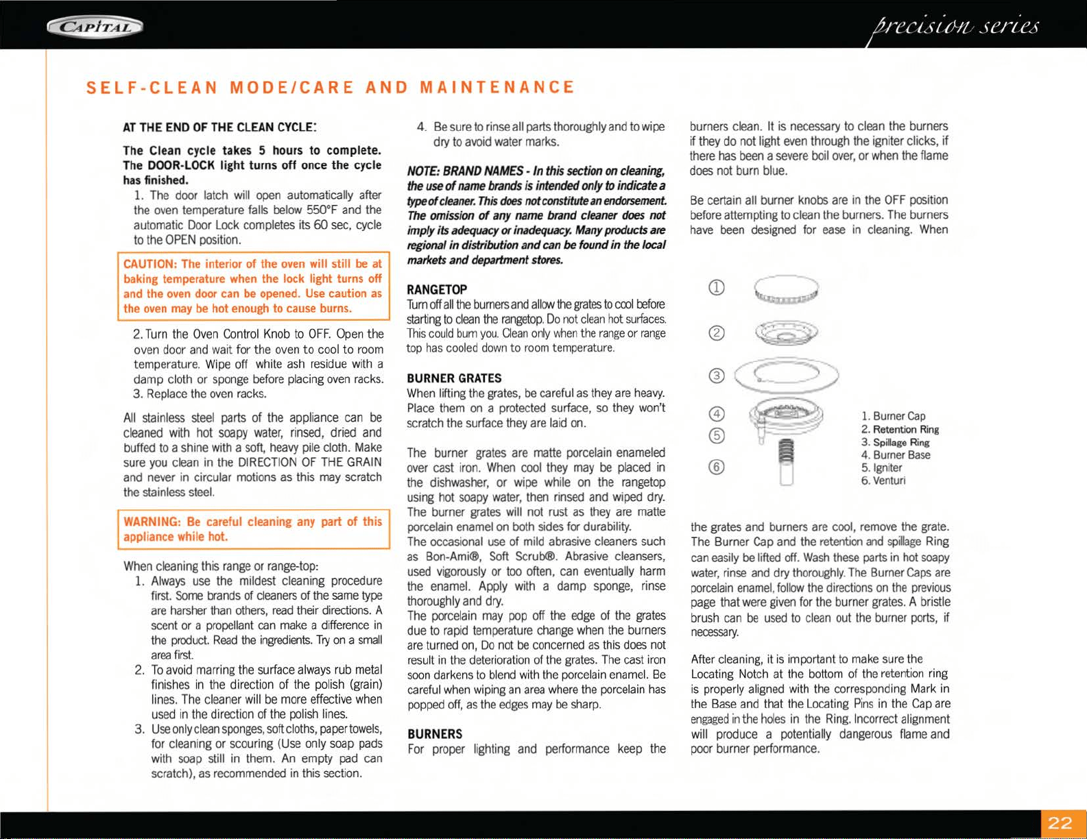
SELF-CLEAN
MODE/CARE
AND
MAINTENANCE
AT
THE
END
OF
THE
CLEAN
CYCLE:
The
Clean
cycle takes 5 hours to complete.
The
DOOR
-
LOCK
light turns off
once
the cycle
has
finished.
1.
The
door
latch
will
open
automatically
after
the
oven
temperature
falls
below
550°F
and
the
automatic
Door
Lock
completes
its
60
sec,
cycle
to
the
OPEN
posi
ti
on.
UTION:
The
interior of
the
oven
will still
be
at
king
temperature
when
the
lock light turns off
d
the
oven
door
can
be
opened.
Use
caution
as
e
oven
may
be
hot
enough
to
cause
burns.
2.
T
urn
the
Oven
Control
Knob
to
OFF.
Op
en
the
oven
door
and
wa
it
for
the
oven
to
cool
to
room
temperature
.
Wi
pe
off
wh
ite
ash
residue
with
a
damp
cloth
or
spo
ng
e
before
placing
oven
racks.
3.
Replace
the
oven
racks.
All
stainless
steel
parts
of
the
appliance
can
be
cleaned
with
hot
soapy
water,
rinsed,
dried
and
buffed
to
a
shine
with
a
soft
,
heavy
pile
cloth.
Make
sure
you
clean
in
the
DI
RECTION
OF
THE
GRAIN
and
never
in
circular
motions
as
this
may
scratch
the
stainless
steel.
f'WARNING:
Be
careful
cleaning
any
part
of this
I
~ppliance
while
hot.
----------------~
When
cleaning
this
range
or
range-top:
1.
A
lw
ays
use
the
mildest
cleaning
pr
ocedure
first.
Some
br
ands
of
cleaners
of
the
same
type
are
harsher
than
others,
read
thei
r
directions.
A
sce
nt
or
a pr
opellant
ca
n
make
a
differen
ce
in
the
product.
R
ead
the
ingred
i
ents.
Try
on
a
small
area
first.
2.
To
a
vo
id
marr
in
g
the
surface
always
rub
metal
fin
ish
es
in
the
dire
ction of
the
polish
(grain)
lin
es.
Th
e
cleaner
will
be
more
effective
when
used
in
the
direction
of
the
polish
lines.
3.
Use
only
clean
sponges,
soft
cl
oths,
paper
towels,
for
cl
ea
nin
g
or
scouring
(Use
on
ly
soap
pads
with
soap
still
in
them.
An
empty
pad
can
scratch),
as
recommended
in
this
section.
4.
Be
sure
to
rinse
all
parts
thoroughly
and
to
wipe
dry
to
avoid
water
marks.
NOTE
:
BRAND
NAMES
- In th
is
section
on
cleaning,
the
use
of
name
brands
is
in
tended
only
to
indicate
a
type
of
cleaner.
This
does
not
constitute
an
endorsement
.
The
omission
of
any
name
brand
cleaner
does
not
imply its
adequacy
or
inadequacy.
Many
products
are
regional
in
distribution and
can
be
found in the local
markets
and
department
stores.
RANGETOP
Turn
off
all
the
burners
and a
ll
cm
the
g
rates
to
coo
l
before
start
i
ng
to
clean
the
ra
n
ge
t
op.
Do
not
clean
hot
surfaces.
This
cou
ld
bum
you
. Cl
ean
only
when
the
range
or
range
top
has
cooled
down
to
room
temperature
.
BURNER
GRATES
W
hen
lifting
the
grates,
be
careful
as
t
hey
are
heavy.
Place
them
on
a
pro
t
ec
t
ed
surface,
so
they
won't
scratch
the
surface
they
are
laid
on.
The
burner
grates
are
matte
porcelain
enameled
over
cast
iron.
When
cool
they
may
be
placed
in
the
dishwasher,
or
wipe
while
on
the
rangetop
using
hot
soapy
water,
then
rinsed
and
wiped
dry.
The
burner
grates
will
not
rust
as
they
are
matte
porcelain
enamel
on
both
sides
for
durability.
The
occasional
use
of
mild
abrasive
cleaners
such
as
Bon-Ami®,
Soft
Scrub®.
Abrasive
cleansers,
used
vigorously
or
too
often,
can
eventually
harm
the
enamel.
Apply
with
a
damp
sponge,
rinse
thoroughly
and
dry.
The
porcelain
may
pop
off
the
edge
of
the
grates
due
to
rapid
temperature
cha
ng
e
when
the
bu
rners
are
tu
rned
on,
Do
not
be
conce
rned
as
th
is
does
not
resu
lt
in
the
deter
i
orat
i
on
of
the
grates.
The
cast
iro
n
soon
darkens
to
bl
end
with
the
porce
l
ain
en
ame
l.
Be
careful
wh
en w
ip
in
g
an
ar
ea
wh
ere
the
porcelai
n h
as
popped
off,
as
the
edges
may
be
sh
arp.
BURNERS
For
proper
li
ghting
and
performance
k
eep
the
burners
clean.
It
is
necessary
to
clean
the
burners
if
they
do
not
light
even
through
the
igniter
clicks,
if
there
has
been
a
severe
boil
over,
or
when
the
flame
does
not
burn
blue.
Be
certain
all
burner
knobs
are
in
the
OFF
position
before
attempting
to
clean
the
burners.
The
burners
have
been
designed
for
ease
in
cl
eaning.
When
Q)
®
~
,~
®
~
0
®
®
1.
Burner
Cap
2.
Retention
Ring
3.
Spillage
Ring
4. Burner
Base
5.
Ign
i
ter
6.
Ventur
i
the
grates
and
burners
are
cool
,
remove
the
grate.
The
Burner
Cap
and
the
retention
and
sp
i
llage
Ring
can
easily
be
lifted
off.
Wash
these
parts
in
hot
soapy
water,
rinse
and
dry
thoroughly.
The
Burner
Caps
are
porcelain
enamel,
follow
the
directions
on
the
previous
p
age
that
were
given
for
the
burner
grates.
A
bristle
b
rush
can
be
used
to
cl
ean
out
the
burner
ports,
if
necessary.
After
cl
ean
in
g,
it
is i
mportant
to
mak
e sure the
Locating
N
otch
at
the
bo
tt
om
of
th
e
retent
ion
r
ing
is
properly
a
li
gn
ed
with
the
co
rr
espo
nding
M
ar
k
in
the
Base
and
that
the
Locat
in
g
Pins
in
the
Cap
are
engaged
in
the
holes
in
the
Ring.
I
ncorrect
alignment
will
produce
a
potentially
dangerous
flame
and
poor
burner
performance.
IGNITERS
Wipe
w
ith
a
wa
t
er-dampe
n
ed
cotton
swab.
Be
careful
not
to
damage
the
igniter.
(See
illustration).
CONTROL
KNOBS
-
RANGETOP
AND
OVEN
These
are
made
of die-cast
metal
w
ith
pl
ast
ic
inserts
for
easier
g
ri
pp
in
g.
They
can
be
cleaned
in
hot,
soapy
water.
To
remove
the
Knobs
from
th
e
control
panel,
grasp
the
knob
and
pull
st
r
aight
forwa
r
d.
Wash,
do
not
soak.
Rinse
and
dry
tho
r
oughly.
It is
importan
t
to
rep
l
ace
these
knobs
on
the
correct
gas
va
l
ve
on
the
co
n
trol
pane
l.
LOW
BACK ,
OR
HIGH SHELF (IF
INSTALLED)
Depending
on
the
mode
l,
these
are
constructed
of
all
stainless
steel.
Use
the
mildest
cl
eaning
procedure
first - hot
soapy
water,
rinse
and
dry. If
th
e
pa
n
el
has
food
soil
r
ema
inin
g,
try
a
ge
n
era
l
kitchen
cleaner,
such
as
Fa
nt
ast
ik
®,
Simple
Green®,
or
Formula
409®.
For
hard
to
cl
ean
soil
use
a
sta
inl
ess
steel
cleaner
such
as,
Bo
n
-Am
i
®,
Cameo®,
or
Bar
Keepers
Friend.
App
ly cl
ea
ner
wi
th a damp
sponge,
rinse
thoroughly
and
dry.
Always
scrub lightly
in
the
direction of
the
gra
in
.
Do
not
use
a
stee
l
woo
l
pad,
it w
ill
scratch
the
surface.
To
touch
up
noticeable
scratches
in
th
e
stai
n
less
steel,
sand
very
li
ghtly with
dry
100
grit
emery
pape
r, rubbing
in
the
direction
of
the
grain.
Afte
r cl
ean
in
g u
se
a stainless steel
pol ish, such as Sta inless
Steel Magice.
If
the
rear
top
burners
are
used
extensively
on
high
it
is
poss
ib
le
for
the
vertical
stai
n
less
steel
pane
l
to
disco
l
or
from
the
burner
heat.
Th
is di
scoloratio
n
can
be
removed
by
using
Revere
Ware
Sta
inl
ess
Stee
l Cl
eaner.
OVEN
AND
DOOR
INTERIOR
If in the event
the
oven
door comes off track, or
becomes
misa
ligned,
rea
lignment
can
be
ach
i
eved
by
following this simple procedure:
Open
the door
and
hold it all
the
way
open.
Close
the hi
nge
latches.
Once
both
hinges are locked,
ge
ntly lift the door
up
and
partially out un
ti
l the
door is evenly aligned.
Evenly
slide the door back
into
place
and
check
to
assu
re
the
hinges rest
in
the center of
each
door hi
nge
ro
l
ler.
With the
oven
doo
r fully open,
un
l
ock
h
inge
la
tches
and
the door
is ready to close again.
Call
our service technician
if
you encounter difficulty.
Be
sure
the
oven
and
door
are
cool
before
you
start
to
clean
th
em.
Th
ey
are
porce
l
ai
n
ename
l
coated.
It
is
ac
id r
es
i
stant,
but
not
acid
proof.
Therefore,
ac
id
foods,
suc
h
as
vi
n
egar,
r
hubarb
,
alco
h
ol,
citr
ic
juices
or
milk,
shou
ld
be
wiped
off
and
not
allowed
to
brake
on.
T
ry
mild
cleaners
,
such
as:
Bon-Ami®,
Ammon
i
a,
Ammonia
and
wate
r,
or
Soft
Scrub®.
App
ly
th
e
cleaner
on
a
damp
sponge
or
cloth.
Rub
lig
htl
y.
Rinse
thoroughly
and
dry.
If
food
has
bu
rned
onto
the
oven
and
is
difficult
to
remove,
soak
the
spots
with
a cl
oth
satu
rat
ed
with
household
ammonia.
A
ll
ow
it to
soak
for
an
h
our
or
two,
with
the
door
closed.
The
food
so
il
shou
ld
be
easy
to
remove
with a
damp
soapy
cl
oth
or
mild
abras
i
ve.
OVEN
RACKS
AND
ROLLERS
Th
e
ove
n
racks
and
rollers
are
chrome
plated
steel.
Chrome
cleaners
,
suc
h
as
Soft
Scrub®,
Cameo
or
Bar
Keepe
rs
Friend
can
be
app
l
ied
with a
damp
sponge
following
package
directions.
Ri
nse
and
dry.
Powdered
cleaners
suc
h
as
Bon
-A
mi®
or
Comet
are
app
l
ied
with
a
damp
spo
n
ge
or
cl
oth,
rubbed
light
l
y,
ri
n
sed
and
dri
ed.
Harsh
Cleaners
w
hi
ch
are
comme
r
cial
oven
cleaners,
such
as
Easy
Off®
or
Dow
ca
n
be
used
on
the
racks.
However,
some
commercia
l
oven
cleaner's
ca
u
se
darkening
and
discoloration.
Test
the cl
ea
n
er
on
a
small
part
of
the
r
ack
and
check
for
any
disco
l
oration
before
clean
i
ng
the e
nt
ire
rack.
Allow
to
stand
for
15
to
20
mi
n
utes.
Rinse
th
oroughly
and
dry.
FRAMES
,
SIDES,
DOOR
EXTERIOR
,
HEAT
DEFLECTOR
These
parts
are
made
of
stain
l
ess
steel,
follow
the
directions
for
the
Backguard
(see
page
28) .
Take
care
when
cleaning
the
door
top.
Do
not
let
water
or
cleaners
run
down
the
vents.
If
water
or
cl
eaners
spill
into
the
vents,
they
may
streak
the
gl
ass
inside
the
door.
CARE
AND
MAINTENANCE
DOOR
GASKET
Use
a
ge
n
eral
kitchen
spray
cleaner,
su
ch
as
Formula
409®
or
Fantastik®.
Spray
it
and
blot
dry with a
cloth.
Do
not
rub.
Do
not
remove
or
damage
the
gasket.
OVEN
LIGHT
BULB
REPLACEMENT
Fo
r
oven
light
bu
lb
replacement
use
on
ly a 40
watt,
120
volt appliance light b
ul
b.
These
are
available
in
supermarkets.
DO
NOT
use
a
standard
light bulb
in
any
ove
n, the h
eat
w
ill
br
eak
i
t.
TO
REPLACE
THE
LIGHT
BULB:
1.
Be
sure
the
oven
li
ght bulb
switch
is
in
the
off
position.
Let
the
cover
and
the
b
ul
b
coo
l
comp
l
ete
l
y.
2.
Remove
the
li
ght
cove
r,
Turn
the
cover
to th
e
left
(counterclockwise)
to
unscrew
it.
3.
Remove
the
burnt o
ut
bulb.
Rep
la
ce
it w
ith
a 40
watt
app
li
ance
li
g
ht
b
ul
b
on
l
y.
4.
Replace
cove
r.
Turn
circuit br
eake
r
back
on,
if
turned
off.
(See
Caution
be
l
ow).
CAUTION:
Be
sure
the
oven
light switch
(see
page
8, # 11) is in the OFF position
and
the light
cover is cool.
If
the bulb
comes
loose
from
its
base,
turn off the
power
to the
oven
at the circuit
breaker panel, before attempting to
remove
the
bulb
base
from the
socket.
POWER
FAILURE
Th
e bro
il
er
and
oven
burners
cannot
be
turned
on dur
in
g a
power
fa
ilur
e.
To
li
ght the
sea
l
ed
top
bu
rn
er
s,
turn t
he
co
n
tro
l
knob
to
"lite"
hold
a
li
g
ht
ed
match to the
po
rt r
ing.
After the flame is burning
al
l
the
way
aro
u
nd
the
burner,
ad
just the flame
to
the desired height. It is necessary
to
l
ig
ht
eac
h
burner i
nd
iv
id
ually.
Do
not light
more
t
han
one
burner
at
a ti
me.
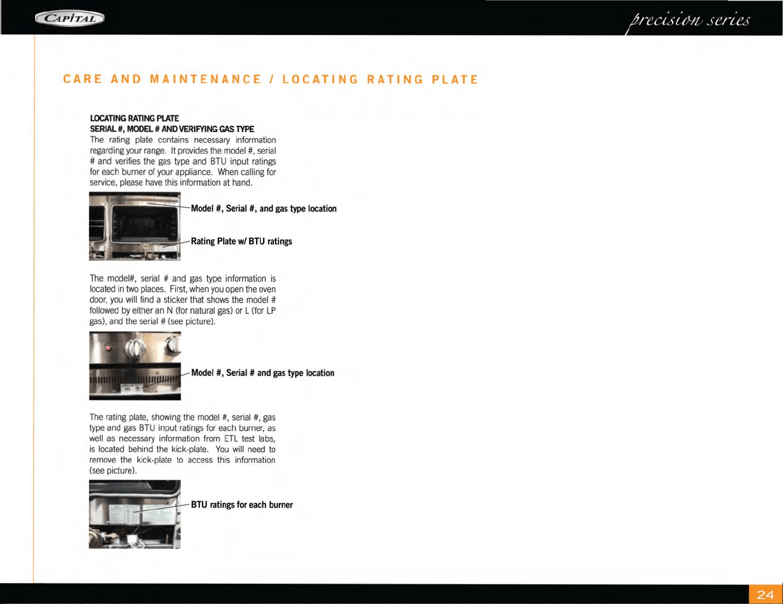
CARE
AND
MAINTENANCE
I
LOCATING
RATING
PLATE
LOCATING
RATING
PLATE
SERIAL#
,
MODEL#
AND
VERIFYING
GAS
TYPE
The
rating
plate
contains
necessary
information
regarding
your
range.
It
provides
the
model#,
serial
#
and
verifies
the
gas
type
and
BTU
input
ratings
for
each
burner
of
your
appliance.
When
calling
for
service,
please
have
this
information
at
hand.
Model#, Serial#,
and
gas
type
location
Rating
Plate
w/
BTU
ratings
The
model#,
se
rial
#
and
gas
type
in
format
ion
is
located
in
two
places.
F
irst
,
when
you
open
the
oven
door,
you
will
find
a sticker that
shows
the
model
#
followed
by
either
an
N (for
natural
gas)
or L (for
LP
gas),
and
the
seria
l #
(see
picture).
Model
#,
Serial
#
and
ga
s type
location
The
rating
plate,
show
ing
the
model#, serial#,
gas
type
and
gas
BTU
input
ratings
for
each
burner,
as
well
as
necessary
information
from
ETL
test
labs
,
is
located
behind
the
kick-plate.
You
will
need
to
remove
the
kick-plate
to
access
this
in
format
i
on
(see
picture).
BTU
ratings
for
each
burner
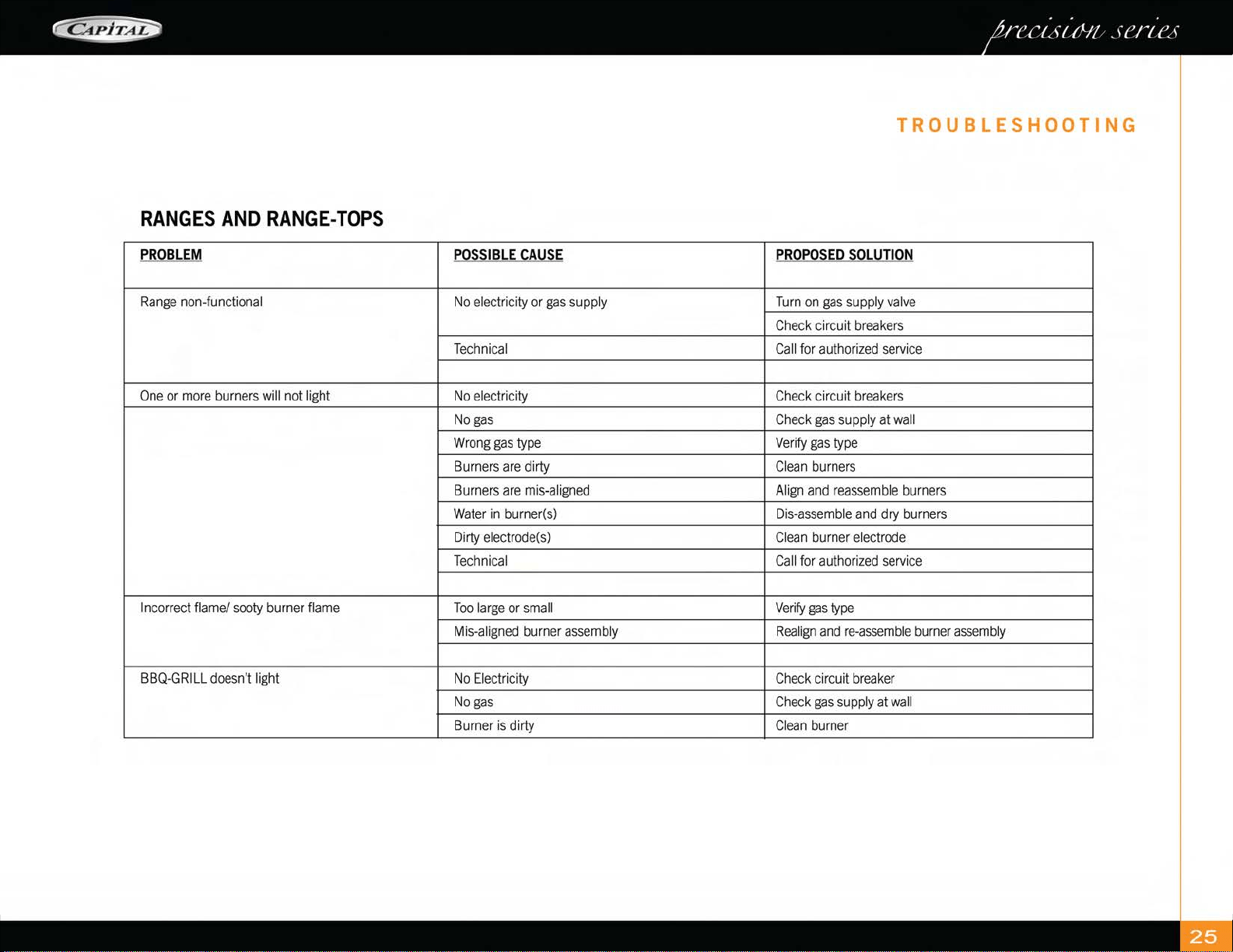
TROUBLESHOOTING
RANGES
AND
RANGE-TOPS
PROBLEM
POSSIBLE
CAUSE
PROPOSED
SOLUTION
R
ange
non-functional
No
el
ect
ri
ci
ty
or
gas
su
pp
ly T
urn
on
gas
supply
valve
Ch
ec
k c
ir
c
ui
t br
ea
kers
Technical
Ca
ll
fo
r autho
ri
zed
serv
i
ce
One
or
more
burners
will
not
light
No
el
ect
ri
ci
ty
Ch
ec
k c
ir
c
ui
t br
ea
kers
No
gas
Ch
ec
k
gas
su
pp
ly at
wa
ll
Wrong
gas
type
Ve
ri
fy
gas
type
B
urn
ers
are
di
rty
Cl
ea
n b
urn
ers
B
urn
ers are mi
s-a
li
gn
ed
A
li
gn and r
eassemb
le b
urn
ers
Water
in
burner(s)
Dis-
assemb
le and
dry
b
urn
ers
Di
rty
el
ectrode(s)
Cle
an
b
urn
er el
ectrode
T
echnical
Ca
ll
fo
r autho
ri
zed
serv
i
ce
I
ncorrect
flame/
sooty
burner
flame
Too
large
or
small
Ve
r
ify
gas
type
Mi
s-a
li
gn
ed
b
urn
er
assemb
ly
Rea
l
ig
n and
re-assemble
bu
rner
assemb
ly
BB
Q-G
RIL
L
doesn't
light
No
El
ect
ri
ci
ty
Ch
eck
ci
rcui
t
brea
k
er
No
gas
Ch
eck
gas
su
pply
at
wall
B
urn
er is di
rty
Cl
ean
bu
rner
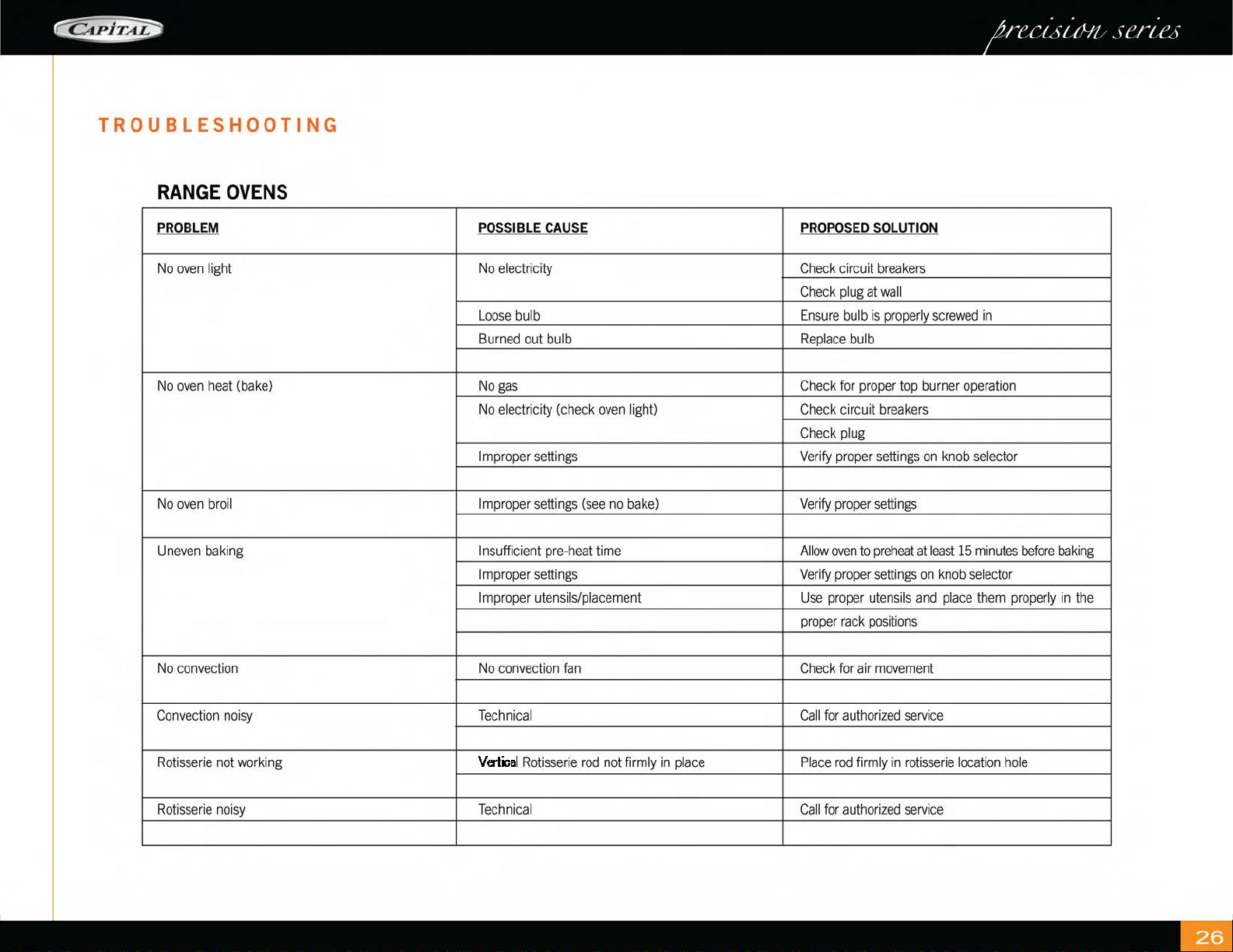
TROUBLESHOOTING
RANGE
OVEN
S
PR
O
BLE
M P
OSS
IBLE
CA
U
SE
PR
QPQS
ED
SQ
LUTI
QN
No
ove
n
li
ght
No
el
ect
ri
ci
ty
Ch
eck
ci
rcui
t
breakers
Ch
eck
pl
ug
at
wall
Loose
b
ul
b En
sure
bulb
is
properly
screwed
in
B
urn
ed
out
bulb
Replace
bulb
No
ove
n h
eat
(ba
k
e)
No
gas
Check
for
proper
top
burner
operation
No
el
ect
ri
ci
ty
(c
h
ec
k
ove
n
li
g
ht
)
Check
circuit
breakers
Check
plug
Imp
r
ope
r
sett
in
gs
Ve
ri
fy
pr
ope
r
se
ttin
gs
on
kn
ob
se
l
ec
tor
No
ove
n bro
il
Imp
r
ope
r
sett
in
gs
(see
no
ba
k
e)
Verify
proper
se
tt
ings
Un
eve
n
ba
kin
g Insufficient pr
e-
h
eat
time
Allow
oven
to
preh
eat
at
least
15
minu
tes
befo
re
baking
Imp
r
ope
r
sett
in
gs
Verify
proper
se
tt
ings
on
kn
ob
se
l
ecto
r
Imp
r
ope
r u
te
ns
il
s/p
l
aceme
nt
Use
pr
oper
utens
i
ls
and
place
them
properly
in
t
he
pr
oper
r
ack
posit
i
ons
No
co
n
vect
ion
No
co
n
vect
ion
fa
n Ch
eck
for
ai
r
movement
Co
n
vect
ion noi
sy
Technical
Call
for
aut
h
orized
serv
i
ce
Rot
i
sse
ri
e n
ot
wo
rkin
g
Vertical
Rotisserie
rod
not
firmly
in
place
Pl
ace
r
od
firm
ly in
rotisserie
loca
ti
on
hole
Rot
i
sse
ri
e noi
sy
Technical
Call
fo
r
aut
h
orized
serv
i
ce

INSTALLATION
INSTRUCTIONS
PRECISION
SERIES
Ranges
SELF
CLEAN
GAS
CONVECTION
MODELS:
GSCR30
(4Q,
4G,
2W,4,5)
GSCR36
(4Q,
4G,
4W
6)
GSCR48
(
4G,
4~
4QG,
6Q,
6G,
8)
GSCR60
(4QG,4QW
4G~
6QG,
6G,
6W)
MANUAL
CLEAN
GAS
CONVECTION
MODELS:
GCR30
(4Q,4G,2W,4,
5)
GCR36
(
4B,
4G,
6)
GCR48
(
4G,
4~
4BG,
6B,
6G,
8)
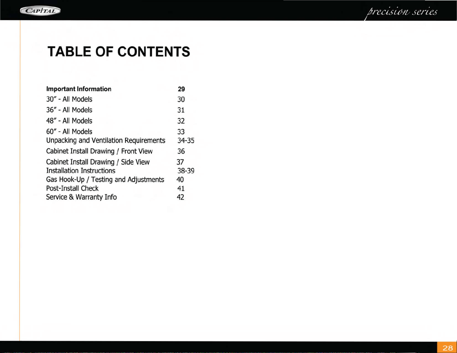
TABLE OF CONTENTS
Important Information
29
30" -
All
Models
30
36"-
All
Models
31
48" -
All
Models
32
60" -
All
Models
33
Unpacking
and
Ventilation Requirements 34-35
Cabinet Install Drawing I Front
View
36
Cabinet Install Drawing I
Side
View
37
Installation Instructions 38-39
Gas
Hook-Up
I Testing
and
Adjustments
40
Post-Install
Check
41
Service
& Warranty Info
42
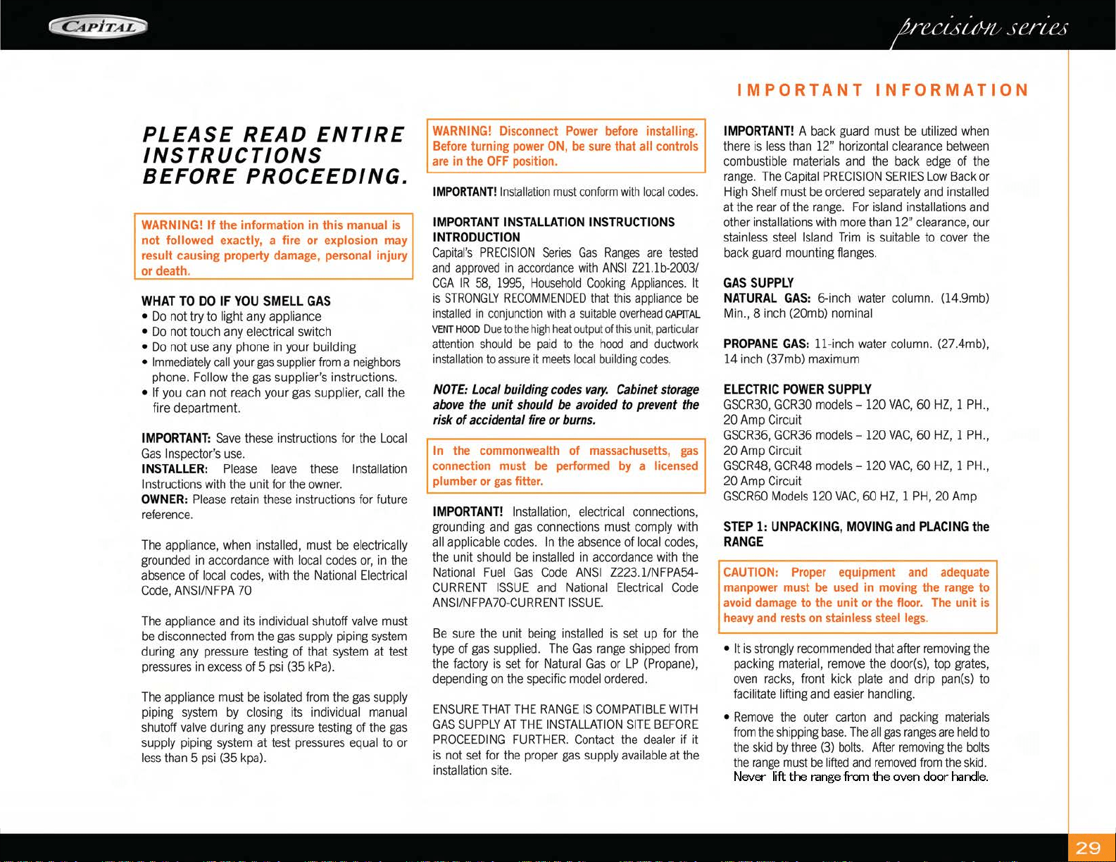
PLEASE
READ
ENTIRE
INSTRUCTIONS
BEFORE
PROCEEDING.
WARNING!
If
the information in this
manual
is
not followed exactly, a fire or explosion
may
result causing property
damage,
personal
injury
or
death.
WHAT
TO
DO
IF
YOU
SMELL
GAS
•
Do
not try to light
any
appliance
•
Do
no
t touch any e
le
ctrical switch
•
Do
no
t
use
any
phone
in
your building
•
Immediately
call
your
gas
suppl
ier fr
om
a
neighbo
rs
phon
e.
Follow
the
gas
supplier
's
inst
ru
ctions.
• If
you
ca
n
no
t
reach
your
gas
suppl
ie
r, call the
fire department.
IMPORTANT:
Save
these
in
st
ru
ct
ions f
or
the
Local
Gas
I
nspector's
u
se.
INSTALLER:
Pl
ease
l
eave
th
ese
Installation
I
nstructions
with
the
unit
for
the
owner.
OWNER:
Please
re
t
ain
th
ese
in
s
tru
c
ti
ons
fo
r
future
reference.
The
app
li
an
ce,
when
in
sta
ll
ed,
must
be
electrically
grounded
in
accordance
with
l
oca
l
codes
or,
in
the
absence
of
local
codes,
w
ith
the
Nat
io
nal
Electrical
Code,
ANSIINFPA
70
The
appliance
and
it
s
in
dividual s
hut
off
va
l
ve
must
be
disconnected
fr
om
the
gas
supply
pip
in
g
system
during
any
pressure
testing
of that
system
at
test
pressures
in
excess
of 5
psi
(35
kPa).
The
appliance
must
be
isolated
from
the
gas
supply
piping
system
by
cl
osing
its
individual
manual
shutoff
valve
during a
ny
pressure
testing
of
the
gas
supply
piping
system
at
test
pr
ess
ur
es
eq
ual
to
or
less
than
5
psi
(35
kpa)
.
WARNING!
Disconnect
Power
before
installing.
Before
turning
power
ON,
be
sure
that all
controls
are
in the
OFF
position.
IMPORTANT!
Installation
must
confor
m w
it
h
local
codes.
IMPORTANT
INSTALLATION
INSTRUCTIONS
INTRODUCTION
Capital's
PRECISION
Ser
ies
Gas
Ranges
a
re
tested
and
ap
proved
in
accordance
with
ANSI
Z2l.l
b
-2003/
CGA
IR
58,
1995,
Household
Cook
i
ng
Appl
i
ances.
It
is
STRONGLY
RECOMMENDED
tha
t
this
app
li
ance
be
installe
d
in
conjunction
with
a
suitable
ove
r
head
CAPITAL
VENT
HOOD
D
ue
to
the
high
heat
output
of
this
unit,
part
i
cular
attention
should
be
pa
id
to
the
hood
and
ductwork
installation
to
assure
it
meets
l
ocal
building
codes.
NOTE: Local building codes
vary.
Cabinet storage
above the
unit
should
be
avoided to prevent the
risk
of
accidental fire
or
burns.
In
the
commonwealth
of
massachusetts,
gas
connection
must
be
performed
by
a
licensed
plumber or
gas
fitter.
IMPORTANT!
Installatio
n, el
ec
trical
connections
,
grounding
and
gas
connect
ions
must
comp
ly
with
all
app
li
cab
le
codes.
In the
absence
of
local
codes,
the
unit sho
ul
d
be
installed
in
accordance
with
the
National
Fuel
Gas
Code
ANSI
Z223.1/NFPA54-
CURRE
NT I
SSUE
and
Nat
io
nal
Electrical
Code
ANSI/NFPA70-CURRENT
ISSUE.
Be
sure
the
unit
being
in
sta
ll
ed
is
set
up
for
the
type
of
gas
supplied.
The
Gas
range
shipped
from
t
he
factory
is
se
t
for
N
atural
Gas
or
LP
(P
ropane),
depending
on
th
e
specific
model
ordered.
ENSURE
THAT
THE
RANGE
IS
COMPAT
IBLE
WITH
GAS
SUPPLY
AT
T
HE
INSTALLATION
SI
TE
BEFORE
PROCEEDING
FURTHER.
Con
t
ac
t t
he
dealer
if
it
is
no
t
set
for
the
proper
gas
supply
available
at t
he
installatio
n
site.
IMPORTANT
INFORMATION
IMPORTANT!
A
back
guard
must
be
utilized
when
th
ere
is
l
ess
than
12"
horizon
t
al
clearance
between
combust
ible
materials
and
the
back
edge
of
the
range.
The
Capi
t
al
PRECISION
SERIES
Low
Back
or
High Shelf
must
be
ordered
sepa
ra
te
ly
and
in
sta
ll
ed
at
the
rear
of
the
range.
F
or
island
ins
t
allations
and
ot
her
in
sta
lla
tions
with
more
than
12"
clearance,
our
sta
inl
ess
stee
l
Is
land
Trim
is suit
ab
le to
cover
the
back
g
uar
d
mounting
f
lan
ges.
GAS
SUPPLY
NATURAL
GAS:
6-inch
wate
r
co
lu
m
n.
(14.9mb)
Min.,
8
in
ch
(20mb)
n
om
inal
PROPANE
GAS
:
ll
-
in
ch
water
co
lu
mn.
(27.4mb),
14
in
ch
(37mb)
maximum
ELECTRIC
POWER
SUPPLY
GSCR30,
GCR30
models- 120
VAC,
60
HZ,
1
PH.,
20
Amp
C
ir
cuit
GSCR36,
GCR36
models
-
120
VAC,
60HZ, 1
PH.,
20
Amp
Circuit
GSCR48,
GCR48
models-
120
VAC
, 60HZ, 1
PH.,
20
Amp
Circuit
GSCR60
Mode
ls
120
VAC,
60
HZ,
1
PH,
20
Amp
STEP
1:
UNPACKING,
MOVING
and
PLACING
the
RANGE
CAUTION:
Proper
equipment
and
adequate
manpower
must
be
used
in
moving
the
range
to
avoid
damage
to the unit
or
the
floor.
The
unit
is
heavy
and
rests
on
stainless
steel
legs.
• It
is
st
rongly r
ecomme
nd
ed
that after
removing
the
packing
ma
t
er
ial,
remove
the
door(s)
,
top
grates,
oven
racks,
front
kick
plate
and
drip
pa
n(s
) to
facilitate
lifting
and
easier
handling.
•
Remove
the
oute
r
carton
a
nd
pack
i
ng
materials
from
the
shipp
i
ng
base.
The
a
ll
gas
ranges
are
held
to
t
he
sk
id
by
th
ree
(3)
bolts.
After
remov
i
ng
the
bo
l
ts
the
ran
ge
mus
t
be
l
ift
ed
and
removed
from
t
he
sk
id.
Never
lift
the
range
from
the
oven
door
handle.
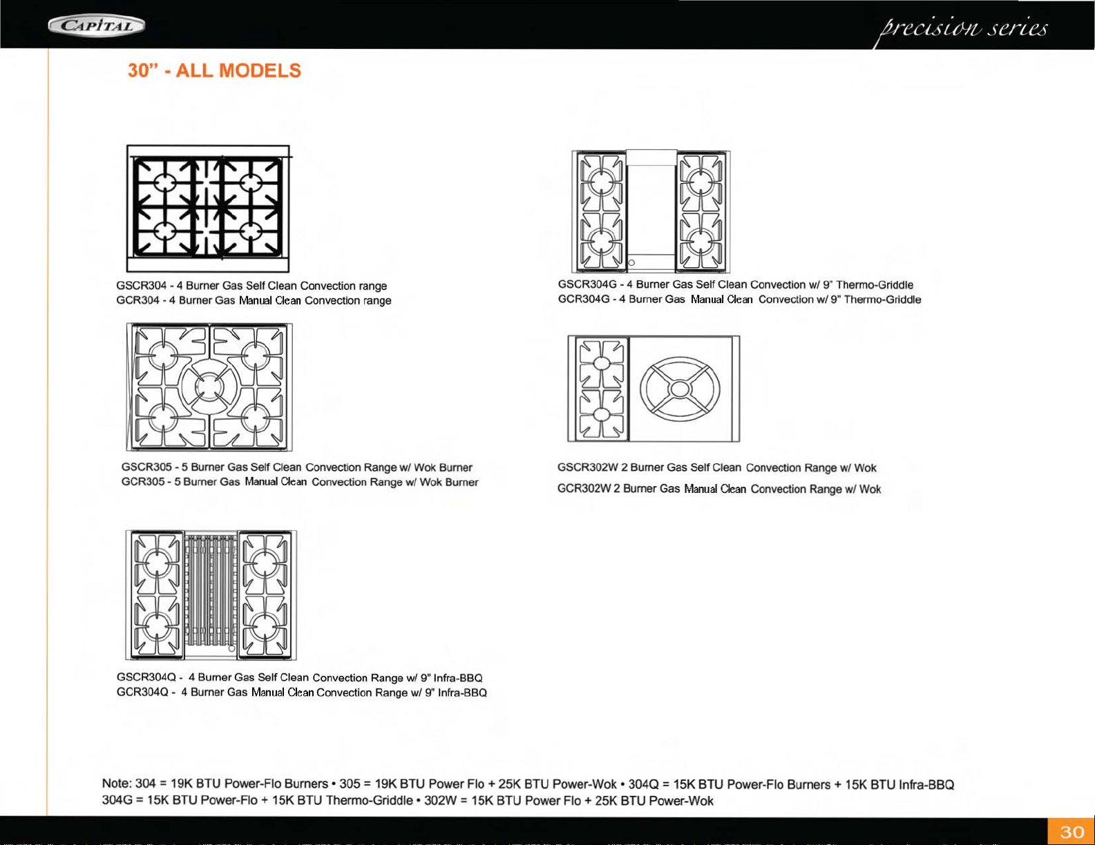
30" - ALL MODELS
GSCR304 - 4 Burner Gas Self Clean Convection range
GCR304
- 4 Burner Gas Manual Clean Convection range
GSCR305 - 5 Burner
Gas
Self
Clean Convection Range w/
Wok
Burner
GCR305 - 5 Burner Gas Manual Clean Convection Range w/
Wok
Burner
GSCR304Q - 4 Burner Gas
Se
lf Clean Convection Range
w/
9" lnfra-BBQ
GCR304Q - 4 Burner Gas Manual Clean Convection Range
w/
9" lnfra-BBQ
(2J
~
~
[QJ
p
GSCR304G - 4 Burner Gas Self Clean Convection
w/9
" Thermo-Griddle
GCR304G - 4 Burner Gas Manual Clean Convection
w/9
" Thermo-Griddle
GSCR302W 2 Burner Gas
Se
lf Cl
ean
Convection Range w/
Wok
GCR302W
2 Burner Gas Manual
Clean
Convection Range w/ Wok
Note: 304 = 19K BTU Power-Flo Burners • 305 = 19K BTU Power
Flo+
25K
BTU Power-Wok •
3040
= 15K BTU Power-Flo
Burners+
15K BTU lnfra-BBQ
304G = 15K BTU Power-Flo+ 15K BTU Thermo-Griddle • 302W = 15K BTU Power
Flo+
25K BTU Power-Wok
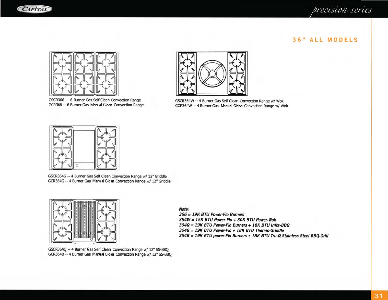
GSCR366
-- 6
Burner
Gas
Self
Oean
Convection
Range
GCR366
-- 6
Burner
Gas
Manual
Clean
Convection
Range
GSCR364G
-- 4
Burner
Gas
Self
Oean
Convection
Range
w/
12
"
Griddle
GCR364G
-- 4
Burner
Gas
Manual
Clean
Convection
Range
w/ 12"
Griddle
GSCR364Q
-- 4
Burner
Gas
Self
Clean
Convection
Range
w/
12"
SS-BBQ
GCR364B
-- 4
Burner
Gas
Manual
Clean
Convection
Range
w/
12"
SS
·
BBQ
GSCR364W
-- 4
Burner
Gas
Self
Clean
Convection
Range
w/
Wok
GCR364W
-- 4
Burner
Gas
Manual
Clean
Convection
Range
w/
Wok
Note
:
366
= 19K
BTU
Power-Flo
Burners
364W = 15K
BTU
Power
Fl
o+
30K
BTU
Power
-Wok
364Q
= 19K
BTU
Po
wer-Flo
Burners +
lBK
BTU
lnfra-
BBQ
3
64G
= 19K
BTU
Power-Flo
+
lBK
BTU
Thermo-Gr
i
ddle
36"
ALL
MODELS
364B = 19K
BTU
power
-
Flo
Burners +
lBK
BTU
Tru
-Q
Sta
inle
ss
Steel
BBQ-Gri/1
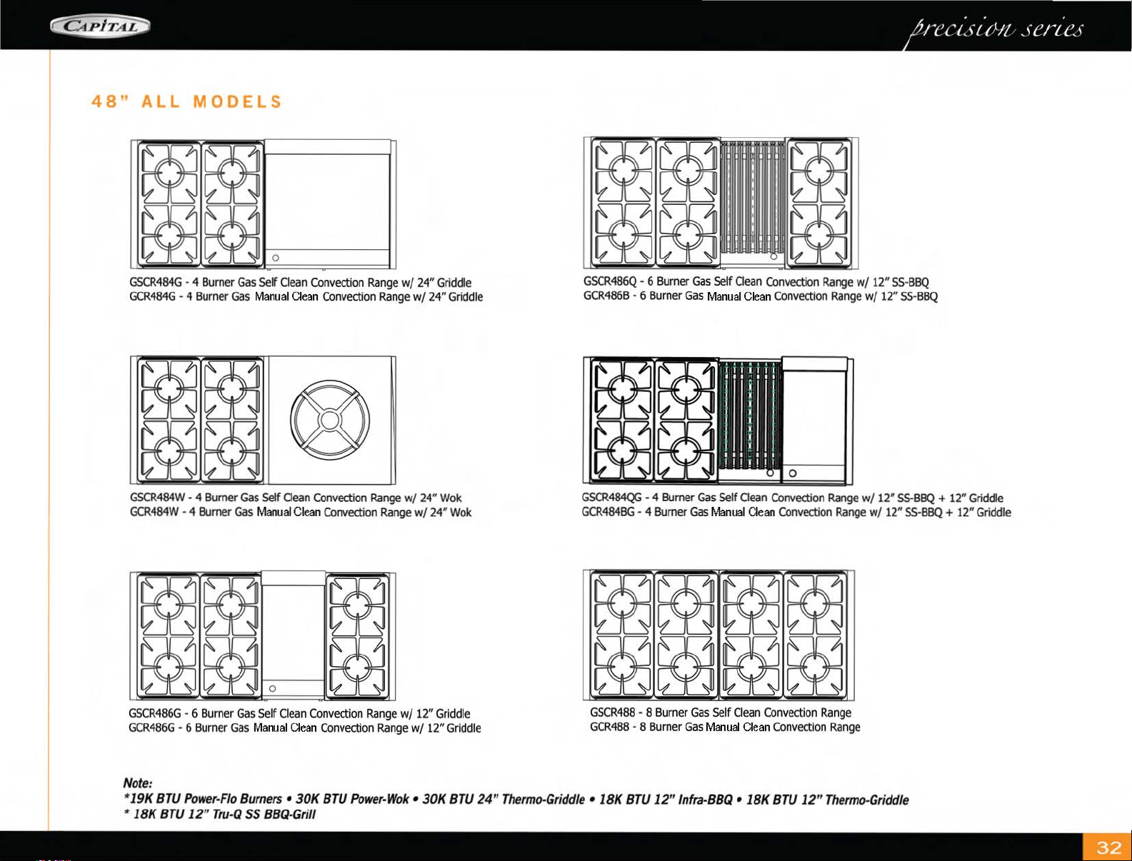
48"
ALL
MODELS
~
~
1-----
0
-1
GSCR484G
- 4
Burner
Gas
Self
Clean
Convection
Range
wf
24"
Griddle
GCR484G
- 4
Burner
Gas
Ma
nual
Clean
Convection
Range
wf
24
"
Griddle
GSCR484W
- 4
Burner
Gas
Self
Oean
Convection
Range
w/
24
"
Wok
GCR484W
- 4
Burner
Gas
Manual
Clean
Convection
Range
w/
24
"
Wok
~
~
~
tQj
~
~
0
GSCR486G
- 6
Burner
Gas
Self
Clean
Convection
Range
wf
12"
Griddle
GCR486G
- 6
Burner
Gas
Manual
Clean
Convection
Range
wf
12"
Griddle
N
ote:
GSCR486Q
- 6
Burner
Gas
Self
Oean
Convection
Range
w/
12"
SS
-
BBQ
GCR486B
- 6
Burner
Gas
Manual
Clean
Convection
Range
w/
12"
SS
-
BBQ
GSCR484QG
- 4
Burner
Gas
Se
.lf aean
Convection
Range
w/
12
"
55
-
BBQ
+
12
"
Griddle
GCR484BG
- 4
Burner
Gas
Manual
Clean
Convectio
n
Range
wf
12
"
SS
-
BBQ
+
12
" G
ri
ddle
~
~
~ ~
~
~
~ ~
GSCR488
- 8
Burner
Gas
Self
Clean
Convection
Range
GCR488
- 8
Burner
Gas
Manual
Clean
Convection
Range
*19K
BTU
P
ower-
F
lo
B
urners
• 30K
BTU
Powe
r-
W
ok
•
30
K
BTU
24" T
hermo-
G
riddle
• 18K
BTU
1
2"
ln
fra
-BBQ
• 18K
BTU
1
2"
T
hermo-
G
riddle
* 18K
BTU
1
2"
Tr
u-
Q
SS
BBQ
-
Gr
ill
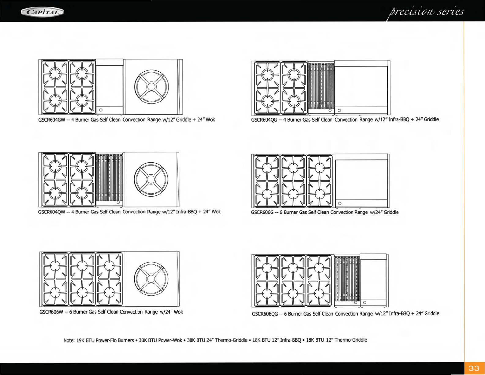
®
GSCR604GW
-- 4
Burner
Gas
Self
Oean
Convection
Range
w/12"
Griddle
+ 24"
Wok
GSCR604QG
-- 4
Burner
Gas
Self
Clean
Convection
Range
w/12"
Infra-BBQ
+ 24"
Griddle
®
83 83
~
~ ~
~
0
GSCR604QW
-- 4
Burner
Gas
Self
Clean
Convection
Range
w/12"
Infra-BBQ
+ 24"
Wok
GSCR606G
-- 6
Burner
Gas
Self
Oean
Convection
Range
w/24"
Griddle
GSCR606W
-- 6
Burner
Gas
Self
Cl
ean
Convection
Range
w/24"
Wok
GSCR606QG
-- 6
Burner
Gas
Self
Clean
Convection
Range
w/12" Infra-
BBQ
+
24"
Griddle
Note:
19K
BTU
Power-Flo
Burners
•
30K
BTU
Power-Wok
•
30K
BTU
24"
Thermo-Griddle
•
18K
BTU
12"
Infra-BBQ
•
18K
BTU
12"
Thermo-Griddle
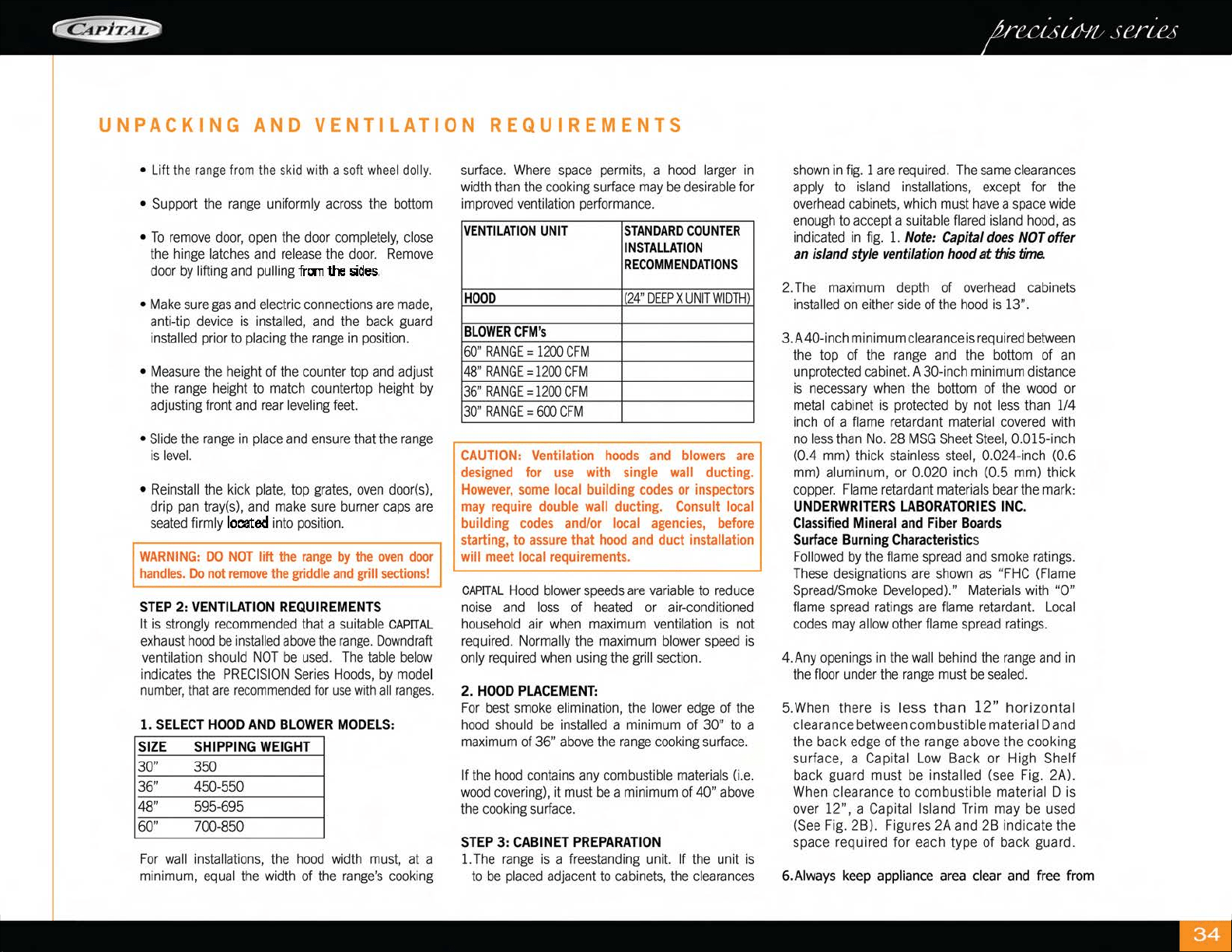
UNPACKING
AND
VENTILATION
REQUIREMENTS
•
Lift
the
range
from
the
skid
wi
th
a
soft
wheel
dolly
.
•
Support
the
range
uniformly
across
the
bottom
•
To
remove
door,
ope
n
the
door
completely,
cl
ose
the
hin
ge
latches
and
release
th
e
door.
Remove
door
by
lifting
and
pulling
frcm
the
5ides.
•
Make
sure
gas
and
electric
co
nn
ect
ions
are
made,
anti-tip
device
is
installed,
a
nd
th
e
bac
k g
uar
d
installed
prior
to
placing
the
range
in
position.
•
Measure
the
height
of
th
e
counter
top
and
ad
just
the
range
height
to
match
co
unt
ertop
he
ight
by
adjusting
front
and
rear
leveling
feet.
•
Slide
the
range
in
pl
ace
and
ensure
that
th
e
range
is
level.
• R
einstall
th
e kick plat
e,
top
gra
t
es,
oven
doo
r
(s),
drip
pa
n
tray(s),
and
make
sure
b
urn
er
caps
are
seated
firmly
located
into
position.
WARNING:
DO
NOT
lift
the
range
by
the
oven
door
handles.
Do
not
remove
the
griddle
and
grill
sections!
STEP
2:
VENTILATION
REQUIREMENTS
It
is
strongly
recommended
that
a
suitable
CAPITA
L
exhaust
hood
be
installed
above
the
range.
Downd
r
aft
ventilation
should
N
OT
be
used.
The
table
be
l
ow
i
ndicates
the
PRECISION
Series
Hoods,
by
mode
l
number,
tha
t
are
recommended
for
use
with
all
ranges.
1.
SELECT
HOOD
AND
BLOWER
MODELS
:
SIZE
SHIPPING
WEIGHT
30" 350
36" 4
50-550
48
"
595
-695
60"
700-850
For
wall
in
sta
ll
at
ion
s,
the
h
ood
width
must,
at a
m
ini
mum,
eq
ual
the
width
of
the
range's
coo
kin
g
surface.
Where
space
pe
rmit
s,
a
hood
l
arger
in
width
than
the
coo
kin
g
surface
may
be
desirable
fo
r
improved
ventilation
performance.
VENTILATION
UNIT
STANDARD
COUNTER
INSTALLATION
RECOMMENDATION
S
HOOD
(24"
DEEP
X
UNIT
WIDTH)
BLOWER
CFM'
s
60"
RANGE
=
1200
CFM
48"
RANGE
=
1200
CFM
36"
RANGE
=
1200
CFM
30"
RANGE
=
600
CFM
CAUTION:
Ventilation
hoods
and
blowers
are
designed
for
use
with
single
wall
ducting.
However,
some
local building
codes
or
inspectors
may
require
double
wall
ducting.
Consult
local
building
codes
and/or
local
agencies,
before
starting, to
assure
that
hood
and
duct installation
will
meet
local
requirements.
CAPITAL
Hood
blower
speeds
are
va
r
iable
to
reduce
no
i
se
and
loss
of
heated
or air-
conditioned
ho
u
seho
ld air
when
maximum
ventilation
is
not
required.
No
r
mally
the
maxim
um
blower
speed
is
on
ly
re
quired
when
using
the
grill
section.
2.
HOOD
PLACEMENT:
For
best
smoke
elimination,
the
l
owe
r
edge
of the
hood
should
be
installed
a m
ini
mum
of 30" to a
maximum
of 36"
above
the
range
cooking
surface.
If
the
hood
co
ntain
s
any
combust
ible
materials
(i
.e.
wood
cove
rin
g),
it
must
be
a
minimum
of
40"
above
the
cooking
surface.
STEP
3:
CABINET
PREPARATION
1.
Th
e
range
is a f
reestanding
unit. If
the
unit is
to
be
placed
adjacent
to
cabinets,
the
cl
ea
ran
ces
shown
in
fig.
1
are
requ
i
red
.
The
same
clearances
apply
to
island
installations,
except
for
the
over
h
ead
cabinets,
w
hi
ch
must
ha
ve
a
space
wide
enough
to
accept
a
suitable
flared
island
hood,
as
indicated
in
fi
g.
1.
Note:
Capital
does
NOT
offer
an island style ventilation
hood
at
tJis
time.
2.
The
max
i
mum
dep
th
of
overhead
cabinets
installed
on
either
side
of
the
hood
is
13".
3.
A40-inch m
in
imum
cleara
n
ce
is
required
between
the top of
the
range
and
the
bottom
of
an
unprotected
cab
in
et.
A 30-
in
ch mini
mum
distance
is
necessary
when
the
bottom
of
the
wood
or
meta
l
cab
i
net
is
pr
otected
by
not
less
than
1/4
inch
of a fl
ame
r
etardant
mater
i
al
covered
with
no
l
ess
tha
n
No.
28
MSG
Sheet
Stee
l, 0.015-
in
ch
(0.4
mm)
thick
stainless
stee
l, 0.024-inch (0.6
mm)
al
umin
um
,
or
0.020
inch
(0.5
mm)
thi
ck
coppe
r.
Fl
ame
re
t
arda
nt
mate
ri
als
bear
the
ma
r
k:
UNDERWRITERS
LABORATORIES
INC
.
Classified
Mineral
and
Fiber
Board
s
Surface
Burning Characteristics
Followed
by
the
fla
me
spread
and
smo
ke
ratings
.
These
designat
i
ons
are
sh
own
as
"FHC
(
Fl
ame
Spread/Smo
ke
Developed)."
Mat
erials
with "0"
flame
spread
rat
in
gs
are
flame
retarda
n
t.
L
ocal
codes
may
allow
other
fl
ame
spread
rat
i
ngs.
4.Any
openings
in
the
wall
be
hin
d
the
range
and
in
the
floor
under
the
range
must
be
sealed.
5.W
hen t
he
re
is
less
than
12"
horizontal
clearance
betwee
n combustible material D and
the back
edge
of the range above the cooking
surface, a
Capital
Low
Back or High Shelf
back guard must
be
insta ll
ed
(see
Fig.
2A).
When
clearan
ce
to combustib
le
material D is
ove
r
12
", a Capita l Island
Tr
im may
be
used
(See
F
ig
. 2Bl. Figur
es
2A
and
2B
in
dicate the
space required for each type of back guard .
6.
Aiways
keep
appliance
area
clear
and
free
from

combustible
materials,
gasoline,
and
other
flammable
vapors
and
liquids.
7.
Models with open broiler, noncombustible
material
is
to
be
installed
on
the
underside
of a
cabine
t
located
above
the
broi
ler
section
or
unit
in
accordance
with
local
codes,
or
in
the
absence
of
local
codes,
with
t
he
National
Fue
l
Gas
code,
ANSI
Z223.1/NFPA
54
.
f\YAR
N I
NG:
DO
NOT
obstructthe
flow
of combustion
~nd
ventilation air to the unit.
PLEASE
NOTE:
In
the
Commonwealth
of
Massachusetts,
gas
connection must
be
performed
by
a licensed
plumber
or
licensed
gas
fitter.
UNPACKING
AND
VENTILATION
REQUIREMENTS
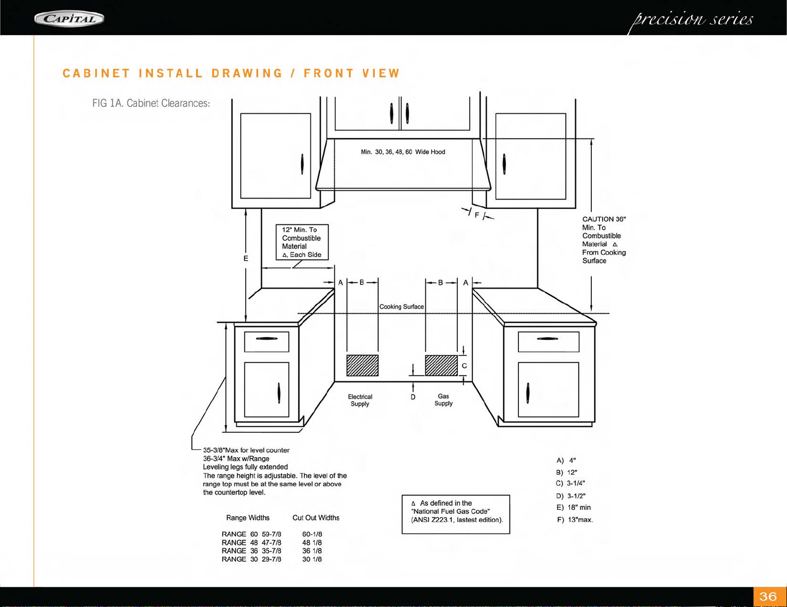
CABINET
INSTALL
DRAWING
I
FRONT
VIEW
FIG
lA.
Cabinet
Clearances:
E
I
12" Min. To
Combustible
Material
A.
Each Side
- I
D
35-3/8"Max for level counter
36-3/4" Max w/Range
Leveling legs
fully
extended
The range height is
adjustable. The level
of
the
range top must be
at
the same level or above
the countertop
level.
Range Widths Cut Out Widths
RANGE
60 59-7/8 60-1/8
RANGE 48 47-7/8
48
1/8
RANGE 36 35-7/8 36 1/8
RANGE
30 29-7/8 30 1/8
Min. 30, 36, 48,
60
Wode
Hood
I
Elecltical
Supply
A As defined in the
"National Fuel Gas Code"
(ANSI Z223.1, lastest edition).
-
A) 4"
B) 12"
CAUTION
36"
Min. To
Combustible
Material
ll
,
From Cooking
Surface
C) 3-1/4"
D) 3-1/2"
E) 18" min
F) 13"max.
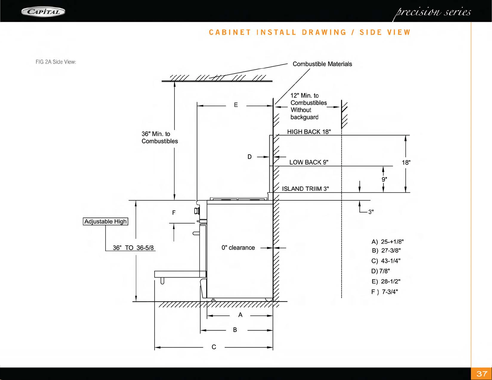
. . .
~
/('Ct,fttfl!
,f('/{(~f
FIG
2A
Side
View:
36" Min. to
Combustibles
36" TO 36-5/8
CABINET
INSTALL
DRAWING
I
SIDE
VIEW
Combustible Materials
E
---Without
~
backguard
HIGH BACK 18" I
D
LOWBACK9"
18"
ISLAND TRIIM 3"
3"
0" clearance
A) 25-+1/8"
B)
27-3/8"
C) 43-1/4"
D)
7/8"
E)
28-1/2"
F)
7-3/4"
A
B
c
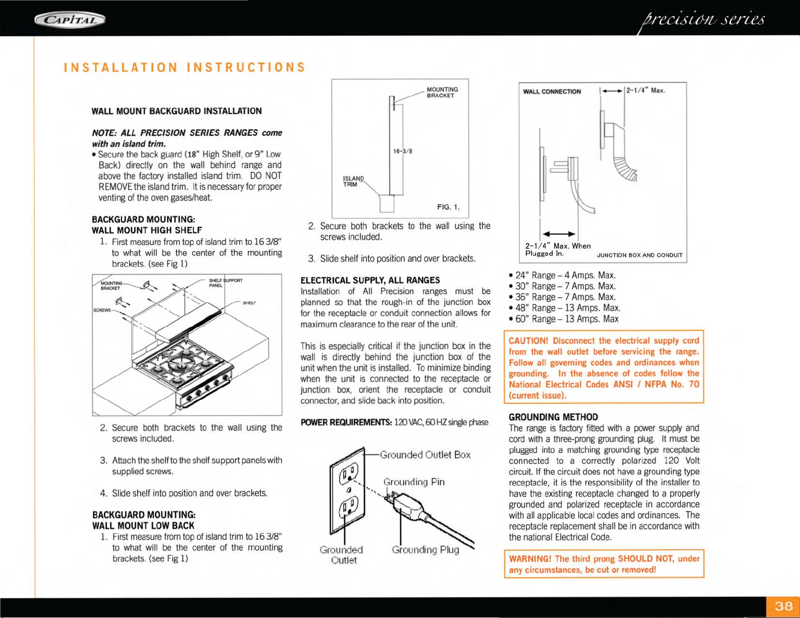
~
. . .
/('
Ct,
ft
tfl!
, fC
11
(~
f
INSTALLATION
INSTRUCTIONS
WALL
MOUNT
BACKGUARD
INSTALLATION
NOTE
:
ALL
PRECISION
SERIES
RANGES
come
with an island
tr
im.
•
Secure
t~e
back
guard
(18
"
High
Shelf,
or
9"
Low
Back)
d1rectly
on
the
wall
behind
range
and
above
the
factory
installed
island
trim.
DO
NOT
REMOVE
the
island
trim.
It
is
necessary
for
proper
venting
of
the
oven
gases/heat.
BACKGUARD
MOUNTING
:
WALL
MOUNT
HIGH
SHELF
1.
First
measure
from
top
of
is
l
and
trim
to
16
3/8"
to
what
w
ill
be
the
center
of
the
mounting
brackets.
(see
Fig
1)
2.
Secure
both
brackets
to
the
wall
using
the
screws
included.
3.
Attach
the
shelf
to
the
shelf
support
panels
with
supp
li
ed
screws.
4. S
li
de
s
he
lf
in
to
pos
iti
on
and
over
brac
k
ets.
BACKGUARD
MOUNTING:
WALL
MOUNT
LOW
BACK
1.
First
measure
from
top
of
island
trim
to
16
3/8"
to
what
will
be
the
center
of
the
mounting
brackets.
(see
Fig
1)
16
- 3/ 8
I \SLAND
L
,.
MOUNTING I
BRACKET
FIG
. 1.
2.
Secure
bot
h
brackets
to
the
wall
using
the
screws
included.
3.
Slide
shelf
into
position
and
over
brackets.
ELECTRICAL
SUPPLY
,
All
RANGES
Ins
t
alla
t
ion
of
All
Precision
ranges
must
be
planned
so
that
the
rough-in
of
the
junction
box
for
the
receptacle
or
conduit
connect
i
on
allows
for
maximum
clearance
to
the
rear
of
the
unit.
This
is
especially
critical
if
the
junction
box
in
the
wall
is
directly
beh
i
nd
the
junction
box
of
the
unit
when
the
unit
is
installed.
To
minimize
bi
nding
when
the
un
it
is
connected
to
the
receptacle
or
junction
box
,
orient
the
receptacle
or
conduit
connector
,
and
sl
i
de
back
into
position.
POWER
REQUIREMENTS
:
120VAC,
ffi
HZsir@e
phase
Grounded
Outlet
Grounded Outlet B
ox
Grounding Pin
W'-LL
CONNECTION
2- 1/ 4"
Max
. When
Plugged ln.
1
--
2- 1/ 4"
Max
.
•
24"
Range
- 4
Amps.
Max.
• 30" Range- 7
Amps.
Max.
• 36" Range- 7
Amps.
Max.
• 48"
Range
-
13
Amps.
Max.
•
60"
Range
-
13
Amps.
Max
I
CAUTION!
Disconnect
the
electrical
supply
cord
from
the
wall
outlet
before
servicing
the
range.
Follow
all
governing
codes
and
ordinances
when
grounding.
In
the
absence
of
codes
follow
the
I
Nat
iona
l Electrical
Codes
ANSI
I
NFPA
No.
70
. (current
issue).
GROUNDING
METHOD
The
range
is
factory
fitted
with
a
power
supply
and
cord
with
a
three-prong
grounding
pl
ug.
It
must
be
plugged
into
a
matching
grounding
type
receptacle
connected
to
a correctly
po
l
arized
120
Volt
circuit.
If
the
circuit
does
not
have
a
grounding
type
receptacle,
it
is
the
r
espo
nsibility
of
the
in
sta
ll
er
to
h
ave
the
ex
i
st
in
g
receptacle
changed
to
a
proper
ly
grounded
and
po
l
arized
r
ecep
tacle
in
accorda
nce
with
a
ll
app
li
cab
le l
oca
l
codes
and
ord
inan
ces.
The
re
ceptac
le
replacement
shall
be
in
accordance
with
the
national
Electrical
Code.
WARNING!
The
third
prong
SHOULD
NOT,
under
any
circumstances,
be
cut
or
removed!

STEP
4:
INSTALLING
ANTI-TIP
DEVICE
For
all
Ra
n
ges,
an
anti-tip
device
MUST
be
installed
as
per
these
instructions.
@@
WARNING!
•
ALL
RANGES
CAN
TIP
•
IN
J
UR
Y
TO
PERSONS
COULD
RESULT
• I
NST
ALL
ANTI-TIP
DEV
I
CES
PACKED
W
IT
H
RANGE
•
SEE
IN
STALLAT
I
ON
I
NSTRUCT
I
ON
WARNING:
RANGE
TIPPING
HAZARD!
•
All
ranges
can
ti
p
and
injury
can
r
esult.
To
prevent
accide
n
tal
tipping of the
ra
n
ge,
attach it
to
the
fl
oor,
wall
or
cab
in
et
by
ins
talling
the
Anti-Tip
Device
supp
l
ied.
• A
risk
of
tip-over
may
exist
if
the
appliance
is
not
in
sta
ll
ed
in
accorda
n
ce
with th
ese
in
str
u
ct
ion
s.
• If
the
range
is
pulled
away
from
the
wall
for
cl
ean
in
g,
service
or
any
ot
her
reason,
ens
ur
e
that
the
Anti-Tip
Dev
i
ce
is
properly
re-engaged
when
the
ra
n
ge
is
pushed
back
aga
in
st t
he
wall.
In
the
event
of
ab
n
orma
l
usage
(such
as
a
person
stand
in
g,
sitting,
or l
ea
nin
g
on
an
open
door),
fa
il
ure
to
take
this
precaution
can
resu
lt
in
tipping
of the
range.
Personal
injury might
result
from
sp
ill
ed
h
ot
li
q
ui
ds
or
from
the
range
i
tse
l
f.
WARNING:
ELECTRICAL
SHOCK
HAZARD!
•
Use
extreme
caution
when drilling hol
es
into
the
wa
ll
or
floor.
There
may
be
concealed
electrical
wires
l
ocated
beh
ind
the
wa
ll
or
und
er
the
fl
oor.
•
Identify
th
e
electrical
circuits that
co
ul
d
be
affected
by
the
installation
of
the
Anti
-
Tip
Dev
i
ce,
then
turn
off
power
to
these
c
ir
cu
i
ts.
•
Fa
ilure
to
follow
th
ese
in
s
tru
c
ti
ons
may
result
in
electrical
shock
or
other
personal
injury.
CAUTION:
PROPERTY
DAMAGE!
•
Contact
a q
uali
fi
ed
in
sta
ll
er or contractor
to
determine
the
proper
method
fo
r dr
illi
ng
holes
through
th
e
wall
or
floor
materia
l
(such
as
ceramic
tile,
hardwood,
marble,
etc.)
•
DO
NOT
slide
range
across
unprotected floor.
•
Fa
il
ure
to
follow
these
in
str
uctions
may
result
in
damage
to
wall
or
floor
coverings.
TOOL
S
NEEDED
FOR
INSTALLATION
OF
ANTI-TIP
DEVICE!
1.
Screwdriver
,
Phillips
2.
Dr
ill
, el
ectr
ic
or
h
and
3.
Meas
urin
g t
ape
or
ru
l
er
4.
1/8" dr
ill
bit
(wood
or
metal
wall
or
floor)
5.
3116"
anchor
s,
drywall,
or
concrete,
2
eac
h (not
required
if
mounting
bracket
is
being
attached
to
solid
wood
or
metal.
6.
Hammer
7.
Penc
il
or
ot
h
er
marker
IMPORTANT
INSTALLATION
INFORMATION
•
Th
e
Anti-Tip
Br
acket
may
be
a
tta
ch
ed
to
a
solid
wood
cabinet
having
a
min
i
mum
wall
thickness
of
3/4".
ANT
I·
TIP
BRACKET
MOD
EL
A
30" 14
·151
16"
36" 17·
15116"
48
"
23
·1511
6"
60" 24
·15116"
INSTALLATION
INSTRUCTIONS
•
The
thi
ck
n
ess
of
the
wall
or
fl
oo
r
may
require
use
of
longer
screws,
ava
i
lab
le
at
your
local
ha
r
dware
store.
•
In
all
cases
at l
east
one
(1) of
the
bracket
mount
i
ng
screws
must
be
fastened
to
so
li
d
wood
or
meta
l
on
each
side.
•
Use
appropriate
anchors
wh
en
fasten
i
ng
the
mounting
br
acket
to
any
mater
ial
other
than
hardwood
or
metal.
MOUNTING
ANTI-TIP
BRACKET:
Th
e
alternative
floor
mounted
bracket
shall
be
in
sta
ll
ed
as
fo
ll
ows:
• Pl
ace
bracket
on
floo
r in
pos
iti
on
shown
in Fi
gure
be
l
ow.
•
Secure
to
fl
oor
or
wa
ll
stud.
•
Late
r,
when
unit
is
installed,
the
ad
ju
stab
le l
eg
w
ill
slide
under
the
bracket
STEP
5:
GAS
CONNECTION
AND
HOOK-UP
Verify
the
type
of
gas
being
u
sed
at
the
in
sta
ll
ation
si
te
matches
the
gas
type
of
the
r
ange
.
As
s
hi
pped
from
the
f
ac
t
ory,
units
are
configured
for
use
with
Natura
l
Gas
or
Propane
(L
P).
Make
certa
in
the
range
matches
the
type
of
gas
ava
il
ab
le at
the
location.
Fo
r
installation
of t
he
appliance
at
high
a
ltitu
de,
pl
ease
consult
your
local
gas
company
for
the
ir
r
ecommendat
i
on
of
the
correct
orifice
sizes
and
a
ny
ot
h
er
necessary
adjustments
that
will
provide
prope
r
gas
comb
u
st
ion at
spec
ifi
ed
altit
ud
es.
NOTE: Capital
DOES
NOT supply ranges to match
varying altitudes. Orifices to adjust for combustion
for differing altitudes may
be purchased through
Capital Cooking Equipment by calling our Parts
Department
at
1-866-402-4600,
or email us
at
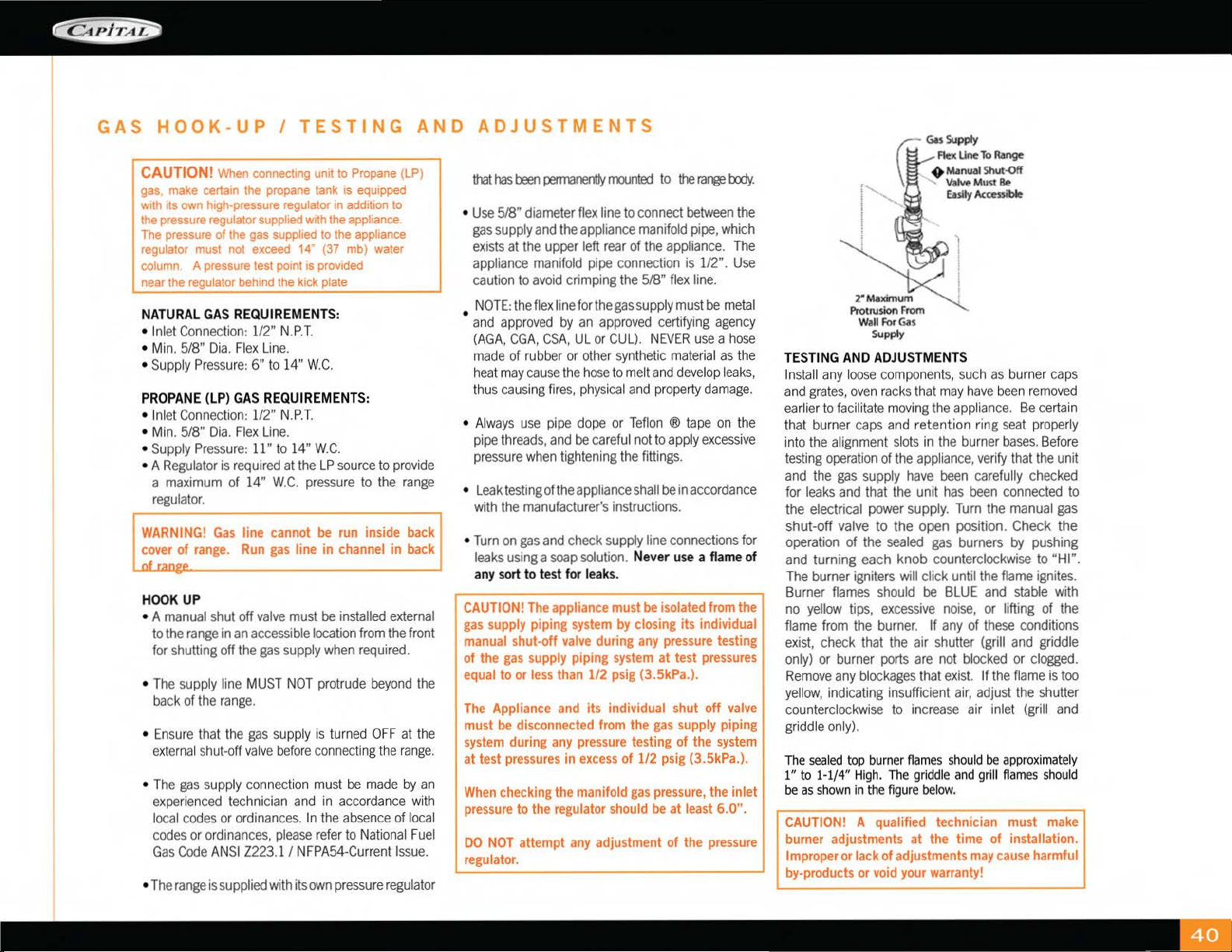
GAS
HOOK-UP
I
TESTING
AND
ADJUSTMENTS
CAUTION!
When
connectm
g
unit
to
P
ro
pa
ne
(LP)
gas.
make
certa1n
the
propan
e ta
nk
is
equipped
w1th
1ts
own
high-pressure
regul
at
or
in
a
ddi
tion
to
the
pressure
regulator
supplied
with
the
app
li
an
ce
.
The
pressure
of
the
gas
supp
l
ied
to
th
e a
ppli
an
ce
regulator
mus
t
no
t
exceed
14 (37 mb) water
column
. A
pressure
t
est
point
is
pro
v
id
ed
near
the
regu
l
ator
behmd
th
e
ki
ck
pl
ate
NATURAL
GA
S
REQUIREMENTS:
•
Inlet
Connection:
1/2"
N.P.
T.
•
Min.
5/8"
Dia.
Flex
Line.
•
Supply
Pressure:
6"
to
14"
W.C.
PROPANE
(LP
)
GAS
REQUIREMENTS:
• Inlet
Connection:
1/2"
N.P.T.
•
Min.
5/8"
Dia.
Flex
Line.
•
Supply
Pressure:
11"
to
14"
W.C.
• A
Regulator
is
required
at
the
LP
source
to
provide
a
maximum
of
14"
W.C.
pressure
to
the
range
regulator.
WARNING!
--
G
-
a
-
s-li_n_e_c_a-nn_o_t-~---ru-n--in-s-id_e_b_a_c-,kl
cover
of
range.
Run
gas
line
in
channel
in
back
HOOK
UP
• A
manual
shut
off
valve
must
be
installed
external
to
the
range
in
an
accessible
location
from
the
front
for
shutting
off
the
gas
supply
when
required.
•
The
supply
line
MUST
NOT
protrude
beyond
the
back
of
the
range.
•
Ensure
that
the
gas
supp
ly is
turned
O
FF
at
the
externa
l
shut-off
valve
before
connect
i
ng
t
he
r
ange.
•
The
gas
supply
co
nn
ect
ion
must
be
made
by
an
exper
i
enced
technician
and
in
accordance
wi
th
l
oca
l
codes
or
ordinances.
In
the
absence
of l
oca
l
codes
or
ord
i
nances,
pl
ease
refer
to
Nat
i
ona
l
Fuel
Gas
Code
ANSI
Z223.1/
NFPA54-Current
I
ssue.
•
The
range
is
supplied
with
its
own
pressure
regulator
that
has
been
permanently
rrounted
to
the
range
body.
•
Use
518"
diameter
flex
line
to
connect
~tween
the
gas
supply
and
the
appliance
manifold
pipe,
which
exists
at
the
upper
left
rear
of
the
appliance.
The
appliance
manifold
pipe
connection
is
112".
Use
caution
to
avoid
crimping
the
5/8"
flex
line.
NOTE:
the
flex
line
for
the
gas
supply
must
be
metal
• and
app
r
oved
by
an
approved
cert
i
fying
agency
(AGA,
CGA,
CSA,
UL
or
CUL).
NEVER
use
a h
ose
made
of
ru
bber
or
other
synthet
ic
ma
t
erial
as
the
hea
t
may
cause
the
hose
to
me
lt
an
d
develop
l
eaks,
t
hu
s
causing
f
ir
es,
physica
l and
property
damage.
• Al
ways
use
pipe
dope
or
Tef
l
on
® t
ape
on
the
pipe
threads,
and
be
careful
not
to
apply
excessive
pressure
when
tightening
the
fittings.
•
Leak
testing
ofthe a
pplia
nee
sha
II
be
in
accord
a
nee
with
the
manufacturer's
instructions.
•
Turn
on
gas
and
check
supply
line
connections
for
leaks
using
a
soap
solution.
Ne
ver u
se
a fl
am
e of
any sort to t
es
t for le
ak
s.
CAUTION!
The
appliance
must~
isolated
from
the
I
gas
supply
piping
system
by
closing its individual
manual
shut-off
valve
during
any
pressure
testing
of the
gas
supply
piping
system
at test
pressures
equal
to
or
less
than
112
psig
(3
.
5kPa.)
.
The
Appliance
and
its individual shut off
valve
must
be
disconnected
from
the
gas
supply
piping
system
during
any
pressure
testing of the
system
at test
pressures
in
excess
of 1/2
psig
(3.5kPa.).
When
checking
the
manifold
gas
pressure,
the inlet
pressure
to the
regulator
should
be
at
least
6.0".
DO
NOT
attempt
any
adjustment of
the
pressure
regulator
.
GuSu
pply
Flex
line
To
Range
+
Manual
Shut-<:>tr
..._
V•IW
Must
Be
Easily
Accessi
ble
TESTING
AND
ADJUSTMENTS
I
nstall
any
l
oose
components,
such
as
burne
r
caps
and
grates,
ove
n
racks
that
may
have
bee
n
removed
earlier
to f
acili
tate
moving
the
app
lian
ce.
Be
certain
that
burner
caps
an
d retention ri
ng
seat
proper
ly
i
nto
the
alignment
slots
in
the
burne
r
bases.
Be
f
ore
testing
operation
of
the
app
l
iance,
verify
that
the
unit
and
the
gas
supply
have
been
carefu
ll
y
checked
for
leaks
and
that
the
unit
has
been
connected
to
the electrical
power
supply.
Turn
the
manual
gas
shut-off
valve
to the open position. Check the
operation
of
the
sealed
gas
burners
by
pushing
and
turning each knob
counterclockwise
to
"HI".
The
burner
igniters
will
click until
the
flame
ignites.
Burner
flames
should
be
BLUE
and
stable
with
no
yellow
tips,
excessive
noise,
or lifting
of
the
flame
from
the
burner.
If
any
of
these
conditions
exist
check
that
the
air
shutter
(grill
and
griddle
only)
or
burner
ports
are
not
blocked
or
clogged.
Remove
any
blockages
that
exist.
If
the
flame
is
too
yellow,
indicating insufficient
air,
adjust
the
shutter
coun
t
erclockwise
to
increase
air inl
et
(grill
and
griddle
only).
The
sealed
top
burn
er
flam
es
s
hould
be
approximately
1"
to
1-1/4"
Hi
gh
.
Th
e
griddl
e
and
gr
i
ll
flames
should
be
as
shown
in
th
e
figur
e be
low
.
CAUTION!
A qualified technician
must
make
burner adjustments at the time
of
installation.
Improper
or lack of
adjustments
may
cause
harmful
by-products
or
void
your
warranty!
----------1
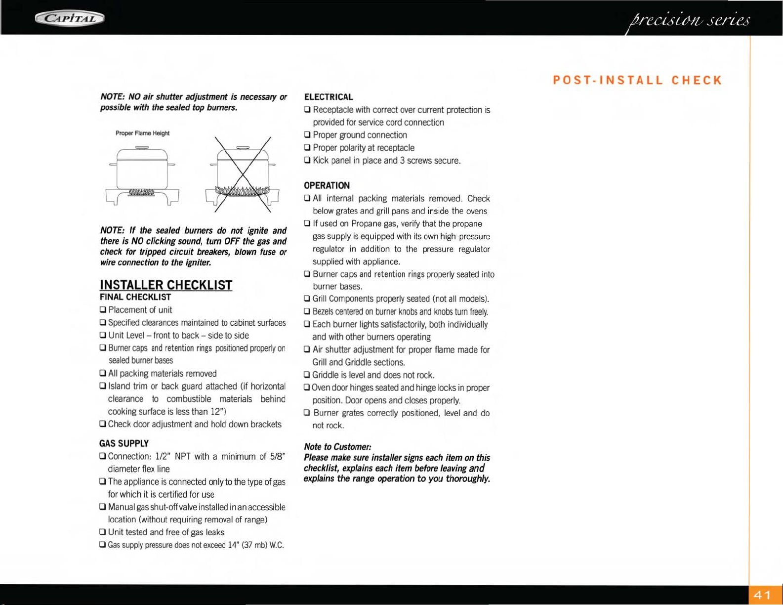
NOTE:
NO
air
shu
tt
er adjustment is necessary or
ELE
CT
RI
CAL
possible with the sealed top burners. 0
Receptacle
with
correct
over
current
protection
is
provided
for
service
cord
connection
Proper Flame Height 0
Proper
ground
connection
NOTE:
If
the sealed burners do
not
ignite
and
there is
NO
clicking sou
nd
, turn
OFF
the gas
and
check for tripped
circuit
breakers, blown fuse
or
wire connection to the igniter.
INSTALLER
CHECKLIST
FINAL
C
HEC
KLIS
T
o
Placement
of unit
0
Specified
clearances
maintained
to
cabinet
surfaces
0 Unit
Level
-
front
to
back-
side
to
side
0
Burner
caps
and
retention
rings
positioned
properly
on
sea
l
ed
burner
bases
0
All
packing
materials
removed
0
Island
trim
or
back
guard
attached
(if
horizontal
clearance
to
combustible
materials
behind
cooking
surface
is
less
than
12")
0
Check
door
adjustment
and
hold
down
brackets
GAS S
UPPL
Y
0
Connection:
112"
NPT
with
a
minimum
of
5/8"
diameter
flex
line
0
The
appliance
is
co
nne
cted
only
to
the
type
of
gas
for
which
it
is
certified
for
use
0 M
anual
gas
s
hut
-off
valve
installed
in
an
accessible
location
(w
ithout
requiring
removal
of
range)
0 Unit
tested
and
free
of
gas
leaks
0
Gas
supply
pressure
does
not
exceed
14"
(37mb)
W.C.
0
Proper
polarity
at
receptacle
0
Kick
panel
in
place
and
3
screws
secure.
OPERATION
0
All
internal
packing
materials
removed.
Check
below
grates
and
grill
pans
and
inside
the
ovens
0 If
used
on
Propane
gas,
verify
that
the
propane
gas
s
upp
ly
is
equipped
with
it
s
own
high-pressure
regulator
in
addition
to
the
pressure
regulator
supplied
with
appliance.
0
Burn
er
caps
and
retention
rings
prop
erly
seated
in
to
burner
bases.
0
Grill
Components
properly
seated
(not
all
mode
ls
).
0
Bezels
centered
on
burner
knobs
and
knobs
turn
freely.
0
Each
burner
lights
satisfactorily,
both
individually
and
with
other
burners
operating
0
Air
shutter
adjustment
for
proper
flame
made
for
Grill
and
Griddle
sections.
0
Griddle
is
level
and
does
not
rock.
0
Oven
door
hinges
seated
and
hinge
locks
in
proper
posi
t
ion.
Door
opens
and
closes
properly.
0
Burner
grates
correct
ly
positioned,
level
and
do
not
rock.
Note to
Cu
stomer:
Plea
se
make sure installer signs each item on t
hi
s
checklist, explains each item before leaving
and
explains
the
range
operation
to
you
thoroughly
.
POST-INSTALL
CHECK
SERVICE
&
WARRANTY
INFO
SERVICE
INFORMATION
If
none
of
the
above
has
occurred,
contact
our
customer
service
department
at 1-866-402-4600.
Before
you
call
for
service,
please
have
the
following
information
available:
• Model#
• Serial#
•
D
ate
of Installation
•
Copy
of
Receipt
or Invoice
• A brief
description
of
the
problem
Your
satisfaction
is
our top priority
If
the
problem
persists,
or
is
not
resolved
to your
satisfaction
by
our
service
consultant,
please
write to
us
or fax
us
a letter at:
Capital
Cooking
Equipment, I
nc.
Attn:
Customer
Service
Manager
13211
E. F
lorence
Ave
Santa
Fe
Springs,
CA
90670
USA
Fax
#: 562-903-1167
Email
:
WARRANTY
• ONE (1) year full parts and labor covers entire product.
•
FIVE
(5)
years parts
on
all burners: oven, broiler, stainless BBQ burner,
griddle burners, sealed burners, wok burner,
infra-
BBQ
burner, grill grates, griddle plate.
• Porcelain enamel
is prone
to
normal wear
over
a
period
of
time.
• Lifetime parts against
rust
on all stainless steel panels
and components.
WlLL
PAY
FCR:
All
repair
labor
and
parts
found
to
be
defective
due
to
material
or workmanshipforone{l)
full
year"IN
HOME"
warranty
This
does
not
apply
if
the unit
was
subjected
to other
than
normal
household
use.
An
Authorized
Factory
Agent
must
provide
service
during
normal
working
hours.
No
charges
will
be
made
for
repair
or
replacement
at the
location
of
original
installation.
No
charges
will
be
made
for
defective
factory
parts
returned
pre
-
paid,
through
the
dealer,
and
claimed
within the
warrantyperiod.
All
claims,
regardless
of
warranty or non-warranty
must
be
documented
with
photos
and
detailed
description
and/or
narrative
of
the
problem
and
submitted
to
Capital's
service
department.
Replacement
of
parts
will
be
freight
prepaid
by
Capital
and
shipped
regular
ground.
Any
requests
for
other
than
standard
ground
shipments
must
be
paid
by
customer.
The
company
will
not
be
liable for
additional
transportation
costs,
labor
cost,
taxes
or
export/import
duties
.
This
warranty
shall
not
apply,
nor
can
we
assume
responsibility
for
damage
that might result
from
failure
to
follow
manufacturer's
instructions
or
local
codes
where
the
appliance
has
been
tempered
with
or
altered
in
any
way
or
wh
i
ch,
in
our
judgment,
has
been
subjected
to
misuse,
negligence,
or
accident.
Implied
warranty
shall
not
extend
beyond
the
duration
of this
written
warranty.
This
warranty
is
in
lieu
of
all
warranties,
expressed
or
implied
and
all
other
obligations
or
liability
in
connection
with
the
sale
of
this
product
..
WI
LL
NOT
PAY
FOR:
• I
nstallation
or
start-up.
Shipping
damage
that
is
not
a direct
result
of
packaging
(for
example
freight
handling)
.
•
Service
by
an
unauthorized
agency
•
Use
of
unauthorized
parts.
•
SerAce
during
hoors
dher
than
oomal
v.al<ing
hoors.
• I
mproper
installation.
•
Ser.ice\fisittoteach
you
hcmtooperatethe
appliance,
correct
the installation,
reset
circuit
breakers
or
replace
fuses
.
•
Repair
other
than
normal
household
use.
•
Damage
caused
by
accident,
abuse,
alteration,
misuse,
incorrect
installation
or
installation
not
in
accordance
with
local
codes.
•
Unit(s)
installed
in
non
-
residential
applications.
This
warranty
applies
to
appliances
used
in
residential
application
only.
It
does
net
cCNei
their
use
in
commercia
l
situations.
This
warranty
is for
pnxlucts
purchased
and
retained
in
the
50
States
ci
the
U.S.A,
the
District
ci
Columbia
and
canada
.
This
warranty
appl
i
es
even
if
you
should
m<Ne
during
the
warranty
period
.
Should
the
original
purchaser
sell
the
appliance
during
the
warranty
period,
the
new
cmner
continues
to
be
prctected
until
the
expiration
date
ci
the
orignal
purchaser's
warranty
period
.
This
warrantyg\eS')OOthespecific
legal
rights.
You
may
also
have
ether
rights,
v.tlich
vary
from
State
to
State.
NOTES
DESIGN
YOUR
DREAM
KITCHEN
87027-01
REV
01
ALL
SPECIFICAT
I
ONS
ARE
FOR
PLA
NNIN
G
PURPOSES
O
NL
Y.
REFER
TO
I
NSTALLAT
I
ON
I
NSTRUCT
IONS
AND
CONSULT
YOUR
COUNTERTOP
SUPPLIER
PRIOR
TO
MAKING
COUN
T
ER
OPENING.
IF
YOU
HAVE
AN
Y
QUESTIONS,
PLEASE
CALL
US
AT
866-402-4600
PR
I
OR
TO
CUTT
I
NG
ANY
OPENINGS.
CONSULT
WITH A H
EATING
AND
VEN
T
ILATING
ENG
I
NEER
FOR
YOUR
SPEC
IFIC
VENT
I
LATION
REQUIREMEN
T
S.
FOR
THE
MOST
UP
TO
DATE
USE
AND
CARE
AND
IN
STALLAT
I
ON
I
NSTRUCTIONS
CONTACT
CAP
I
TAL
COOKING
EQUIPMENT,
IN
C.
IN
DI
CATING
T
HE
MODEL#.
DUE
TO
ONGOING
PRODUC
T
IMPROVEMEN
T
S,
WE
RESERVE
THE RI
GHT
TO
CHANGE
THESE
SPEC
IFI
CATIONS,
OR
DESIGNS
WITHOUT
NOTICE.
CERT
IFI
ED
F
OR
USA
AN
D
CANA
DA
C£A
Pf
r
-if;:J
THE
ART
OF
PRECISION™
13211
E.
Florence
Ave.
Santa
Fe
Springs,
CA
90670.
Toll
Free:
866-402-4600
Main:
562-903-1168
Fax:
562-903-1167
Email:
customerservice@cap
it
al
-cook
in
g.com
Website:
www.capital
-
cooking.com.