Loading ...
Loading ...
Loading ...
En
6
Connections and part names
Connections
! Connect the power cord after all the connections between devices have been completed.
Be sure to turn off the power and unplug the power cord from the power outlet whenever making or changing connections.
Refer to the operating instructions for the component to be connected.
! Be sure to use the included power cord.
! Be sure to use the USB cable included with this product or the one that conforms to USB 2.0.
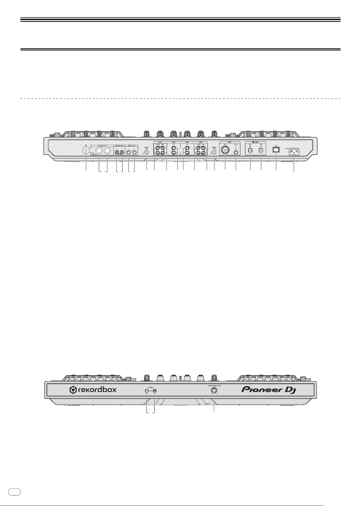
Names of Parts
Rear panel
5 5
3 9 db c e6 7 6 7 a2 4881
1 Kensington security slot
2 MASTER OUT 1 terminals
Connect powered speakers, etc., here.
! Compatible with XLR connector type balanced outputs.
3 MASTER OUT 2 terminals
Connect to a power amplifier, etc.
! Compatible with RCA pin-jack type unbalanced outputs.
4 BOOTH OUT terminals
Output terminals for a booth monitor, compatible with balanced or unbalanced
output for a TRS connector.
The master channel sound can be output from the [BOOTH OUT] terminals
regardless of the audio level set for the master channel.
The volume level can be adjusted with the [BOOTH MONITOR] control.
! The sound will be distorted if the level is raised too high when using unbal-
anced outputs.
5 SIGNAL GND terminal
Connects an analog player’s ground wire here. This helps reduce noise when the
analog player is connected.
6 PHONO terminals
Connect to a phono level (MM cartridge) output device. Do not input line level
signals.
!
You need to set the [LINE, PHONO, USB] selector switch on top of the unit to
[PHONO] beforehand.
7 LINE terminals
Connect to a DJ player or other line level device.
! You need to set the [LINE, PHONO, USB] selector switch on top of the unit to
[LINE] beforehand.
8 CD terminals
Connect to a DJ player or other line level device.
! You need to set the [CD, USB] selector switch on top of the unit to [CD]
beforehand.
9 MIC1 terminal
Connects a microphone here.
! Either an XLR connector or a phones plug (Ø 6.3 mm) can be used.
a MIC2 terminal
Connects a microphone here.
b USB-B terminal
Connect to a computer.
! Connect this unit to your computer directly via a USB cable included with
this product or the one that conforms to USB 2.0.
! A USB hub cannot be used.
c USB-A terminal
Connect to a computer.
! Connect this unit to your computer directly via a USB cable included with
this product or the one that conforms to USB 2.0.
! A USB hub cannot be used.
d u switch
This switches this unit’s power between on and standby.
e AC IN terminal
Connect the power cord after all the connections between devices have been
completed.
Be sure to use the included power cord.
Front panel
12
1 PHONES jacks
Connect headphones here.
Both stereo phone plugs (Ø 6.3 mm) and stereo mini phone plugs (Ø 3.5 mm)
can be used.
! There are two input jacks, both a stereo phones jack and a mini phones jack,
but do not use both simultaneously. If both are used simultaneously, when
one is disconnected and/or connected, the volume of the other may increase
or decrease suddenly.
2 CROSS FADER CURVE selector switch
This switches the crossfader curve characteristics.
! The further the control is turned clockwise, the sharper the curve rises.
! The further the control is turned counterclockwise, the more gradually the
curve rises.
Loading ...
Loading ...
Loading ...