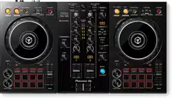
DJ controller
DDJ-RZ
Operating Instructions
http://pioneerdj.com/support/
The Pioneer DJ site shown above offers FAQs, information on software and various other types of information
and services to allow you to use your product in greater comfort.
http://rekordbox.com/
For the latest version of the rekordbox software, access rekordbox.com and download the software from there.
En
2
Contents
How to read this manual
! Thank you for buying this Pioneer DJ product.
Be sure to read this manual and the “Operating Instructions (Quick Start Guide)”
included with the unit. Both documents include important information that you
should understand before using this product.
! In this manual, names of screens and menus displayed on the product and on
the computer screen, as well as names of buttons and terminals, etc., are indi-
cated within brackets. (e.g.: [CUE] button, [Files] panel, [MIC1] terminal)
! Please note that the screens and specifications of the software described in this
manual as well as the external appearance and specifications of the hardware
are currently under development and may differ from the final specifications.
! Please note that depending on the operating system version, web browser set-
tings, etc., operation may differ from the procedures described in this manual.
This manual consists mainly of explanations of functions of this unit as hardware.
For detailed instructions on operating the rekordbox software, see the rekordbox
software’s manual.
! For obtaining the rekordbox software’s manual, see Acquiring the manual
(p. 29 ).
Before start
Features .............................................................................................................................3
What’s in the box ..............................................................................................................4
Preparing the software .....................................................................................................4
Connections and part names
Connections ......................................................................................................................6
Part names and functions ...............................................................................................8
Basic Operation
Connecting this unit and computer ..............................................................................13
Starting the system .........................................................................................................14
Quitting the system ........................................................................................................15
Advanced Operation
Using the performance pads .........................................................................................16
Using the slip mode ........................................................................................................18
Using the dual deck mode .............................................................................................19
Using the fader start function........................................................................................19
Adjusting the crossfader’s operating load ...................................................................20
Using effects ...................................................................................................................20
Using the beat FX function ...........................................................................................20
Using the release FX .......................................................................................................21
Using the SOUND COLOR FX function ........................................................................21
Using the oscillator function .........................................................................................22
Using external inputs .....................................................................................................22
Changing the settings
Launching utilities mode ...............................................................................................24
Utilities modes ................................................................................................................24
About the setting utility software ..................................................................................26
Additional information
Troubleshooting ..............................................................................................................28
Signal flow .......................................................................................................................29
Acquiring the manual ....................................................................................................29
Using as a controller for other DJ software ..................................................................29
About trademarks and registered trademarks ............................................................29
Cautions on copyrights ..................................................................................................30
En
3
Before start
Before start
Features
This unit is an all-in-one DJ controller designed specifically for rekordbox dj.
It’s interfaces incorporating various controls such as “BIG JOG”, “PERFORMANCE
PADS” and 4-channel mixer are positioned with room to spare to allow for more
individualistic DJ performances using rekordbox dj.
Also, the unit provides “SOUND COLOR FX” and “OSC SAMPLER” functions so that
original arrangements can be added to the music being played back.
Furthermore, numerous input and output terminals support a variety of DJ styles.
Featuring aluminum material for the top panel, the design makes the unit look high
quality, which is appropriate in a variety of scenes such as nightclubs, home parties,
etc.
! rekordbox
— rekordbox is a composite software that enables track management and DJ
performances.
! rekordbox dj
— The DJ performance function of rekordbox is called rekordbox dj. Enter the
license key included with this product to use rekordbox dj.
BIG JOG & ON JOG DISPLAY
We have achieved the shortest time required from when jog is operated until when
the control signal is transferred to the software. Additionally, “BIG JOG”, a large
sized jog, allows the DJ to play scratches as they wish with smooth operability.
At the center of the jog, the “ON JOG DISPLAY” displays the playback status of
music and the current playback position so that the DJ can perform scratching
more accurately. Also, the unit is equipped with “JOG FEELING ADJUST”, which is
popular in the CDJ Series. It is possible to adjust the operation load and back spin
continuous time during scratch play to match particular tastes.
MULTI-COLOR PERFORMANCE PADS
“MULTI-COLOR PERFORMANCE PADS”, large rubber pads used to operate func-
tions such as HOT CUE, PAD FX, and SAMPLER, are positioned at the front of the
unit.
Music can be arranged by dynamic actions such as beating and rolling and the
volume of the sampler can be increased or decreased depending on the strength of
the beat.
Also, each pad has built-in multi-color illumination so you can instantaneously
understand the information required for your performance from the color and light-
ing state of the pad.
SEQUENCER
The “SEQUENCER” function that enables recording sampler operation patterns and
playing back recorded sampler operation patterns can be intuitively operated from
the included dedicated operation interface.
DJ performances full of originality are possible as the “SEQUENCER” function and
dedicated operation interface can be used to easily create phrases using sounds
loaded in the sampler.
4-CHANNEL MIXER
The unit includes “4-CHANNEL MIXER”, which allows the DJ to independently oper-
ate songs being played back with four decks. Four songs can be mixed to create a
highly individualistic DJ mix.
Level meters are located near the master unit and the operation interface of each
channel, so that input and output levels can be understood instantly.
This unit retains the control panel layout of the Pioneer DJM series, the world stan-
dard in DJ mixers.
The simple, easy-to-understand control panel layout not only facilitates DJ perfor-
mances but also makes it easy for DJs using the unit for the first time to operate it
without hesitation, so it can be used without worry as a permanently installed mixer
in the club.
OSC SAMPLER
The unit is equipped with the “OSC SAMPLER” function for generating four types of
sound (NOISE, SINE, SIREN, and HORN). Operation is simple. Just press the button
of the sound type you wish to output. You can take music to an entirely new level
by superimposing oscillator sound over the music you are playing back or further
emphasizing the climax of music. Also, you can change the tone by simply turning
the [OSC SAMPLER PARAMETER] control, making it possible to generate oscillator
sound that is matched to the music. Furthermore, you can use sample sounds
saved to the OSC SAMPLER in “rekordbox dj”.
SOUND COLOR FX
The unit is equipped with four “SOUND COLOR FX” functions (SPACE, JET, PITCH,
and FILTER) for achieving a wide range of musical arrangements.
By simply turning the control, it is possible to create the effect you want, and a vari-
ety of remix can be achieved such as adding original arrangements to the music.
Creative effect performances are also made possible by assigning your favorite
SOUND COLOR FX included in “rekordbox dj”.
PLUG AND PLAY DUAL USB PORT
Two USB sound cards are provided to connect the unit to up to two computers at the
same time.
The sound cards of the unit and all buttons and controls are set to be linked with
“rekordbox dj” beforehand so that the DJ can begin performances immediately
using “rekordbox dj” without having to make troublesome settings.
The USB selector located at the top side can be used to switch between the two
sound cards with a single action. When one DJ takes over from another, this func-
tion provides a smooth transition between the two computers without sound being
interrupted.
FLEXIBLE CONNECTIVITY
Four external input systems and two MIC input systems are provided to connect to a
CD player or analog turntable.
Mixing is possible without going through a computer, so the unit can be used as a
single DJ mixer as well.
In addition, two MASTER OUT systems and one BOOTH OUT system are provided to
handle professional PA device output.
All kinds of party scenes and DJ playing styles are supported.
DURABLE FADER
A slide structure is used for the crossfader and channel fader, in which the fader
knob is supported by two metal shafts.
This achieves smooth operability without wobble and also high durability.
Also, effects on inside the faders caused by liquid and dust are minimized.
An independently developed “MAGVEL FADER” magnetic system is equipped for
the crossfader to support scratch play, which provides high durability of more than
10 000 000 operations, and fine operability.
HIGH SOUND QUALITY
Leveraging the audio circuit of Pioneer audio devices for clubs, the unit provides
powerful sound quality faithful to the original. It also reduces contact resistance
through use of an AC inlet having a wide contact area with the power cable, and
achieves stable and powerful sound even in the DJ booth in a loud environment.
By adopting a high performance D/A converter and low jitter crystal oscillator made
by Wolfson Microelectronics, the unit reproduces clear and powerful club sound
faithful to the original.
PROFESSIONAL QUALITY DESIGN
Aluminum material on the top panel and jog plate provides a sense of high quality
design.
This unit is an essential part of DJ performance in clubs and home party scenes.
SLIP MODE
This unit is equipped with a SLIP MODE function to enable sound to continue in the
background while operations such as looping, scratching, and hot cueing are being
performed. This means operations such as looping, scratching, and hot cueing can
be performed without changing the original track’s composition.
NEEDLE SEARCH
Points can be searched for simply by touching the touch pad with a finger. This
makes for intuitive, speedy searching with the sense of touching the music directly.
En
4
What’s in the box
! Power cord
! USB cable
1
! Warranty (for some regions only)
2
! Operating Instructions (Quick Start Guide)
! rekordbox dj license key
1 Only one USB cable is included with this unit.
To connect two units, use a cable conforming to USB 2.0 standards.
2 Products for Japan and Europe only. (For the North American region, the cor-
responding information is provided on the last page of both the English and
French versions of the “Operating Instructions (Quick Start Guide)”.)
Cautions
The license key cannot be reissued. Be careful not to lose it.
Preparing the software
About rekordbox
Acquiring rekordbox (Mac/Windows)
1 Launch a web browser on the computer and access the
rekordbox site below.
http://rekordbox.com/
2 Download rekordbox from the rekordbox download page.
3 Install rekordbox and register the account.
4 Activate rekordbox dj.
! For instructions, see the rekordbox software’s manual.
To activate the rekordbox dj function, enter the rekordbox dj license key supplied
with this product.
About the driver software
This driver software is an exclusive driver for outputting audio signals from a
computer.
! First read the Software end user license agreement on page 5 carefully.
Operating environment
Supported operating systems
Mac OS X 10.10 / 10.9 / 10.8 (latest update)
1
Windows
®
8/8.1 (latest service pack)
32-bit version
1
64-bit version
1
Windows Pro
®
8/8.1 (latest service pack)
32-bit version
1
64-bit version
1
Windows
®
7 Home Premium/Professional/Ultimate (latest service
pack)
32-bit version
1
64-bit version
1
Checking the latest information on the driver software
For the latest information on this unit’s dedicated driver software, see the Pioneer
DJ site below.
http://www.pioneerdj.com/
Obtaining the driver software
1 Launch a web browser on the computer and access the
Pioneer DJ site below.
http://www.pioneerdj.com/
! To switch the screen to Japanese display, scroll the screen to the bottom, click
the [EN] indication at the bottom right of the screen and then select [JA].
2 Click [Support].
3 Click [Software & firmware updates].
4 Click [DDJ-RZ] in the [CONTROLLER] category.
5 After clicking [Drivers], download the latest driver software
from the download page.
Download the driver for either Windows or Mac from the download page.
Installation procedure (Windows)
Do not connect this unit and the computer until installation is completed.
!
Log on as the user which was set as the computer’s administrator before
installing.
! If any other programs are running on the computer, quit them.
1 Obtaining the driver software Double-click the file for
Windows (DDJ-RZ_X.XXX.exe) downloaded in
The driver installation screen appears.
2 Carefully read the Software end user license agreement
and if you consent to the provisions, put a check mark in
[I agree.] and click [OK].
If you do not consent to the provisions of the Software end user license agreement,
click [Cancel] and stop installation.
3 Proceed with installation according to the instructions on
the screen.
If [Windows Security] appears on the screen while the installation is in progress,
click [Install this driver software anyway] and continue with the installation.
When the installation program is completed, a completion message appears.
Installation procedure (Mac OS X)
Do not connect this unit and the computer until installation is completed.
!
If any other programs are running on the computer, quit them.
1 Obtaining the driver software Double-click the file for Mac
(DDJ-RZ_M_X.X.X.dmg) downloaded in
The [DDJ-RZ_AudioDriver] menu screen appears.
2 Double-click [DDJ-RZ_AudioDriver.pkg].
The driver installation screen appears.
3 Check the details on the screen and click [Continue
Anyway].
4 When the end user license agreement appears, read
Software end user license agreement carefully, then click
[Continue Anyway].
5 If you consent to the provisions of the Software end user
license agreement, click [Agree].
If you do not consent to the provisions of the Software end user license agreement,
click [Disagree] and stop installation.
6 Proceed with installation according to the instructions on
the screen.

En
5
Before start
Checking the latest information on the driver
software
For the latest information on this unit’s dedicated driver software, see the Pioneer
DJ site below.
http://www.pioneerdj.com/
Software end user license agreement
This Software End User License Agreement (“Agreement”) is between you (both the
individual installing the Program and any single legal entity for which the individual
is acting) (“You” or “Your”) and Pioneer DJ Corporation (“Pioneer DJ”).
TAKING ANY STEP TO SET UP OR INSTALL THE PROGRAM MEANS THAT YOU
ACCEPT ALL OF THE TERMS OF THIS LICENSE AGREEMENT. PERMISSION TO
DOWNLOAD AND/OR USE THE PROGRAM IS EXPRESSLY CONDITIONED ON
YOUR FOLLOWING THESE TERMS. WRITTEN OR ELECTRONIC APPROVAL IS
NOT REQUIRED TO MAKE THIS AGREEMENT VALID AND ENFORCEABLE. IF
YOU DO NOT AGREE TO ALL OF THE TERMS OF THIS AGREEMENT, YOU ARE
NOT AUTHORIZED TO USE THE PROGRAM AND MUST STOP INSTALLING IT OR
UNINSTALL IT, AS APPLICABLE.
1 DEFINITIONS
1 “Documentation” means written documentation, specifications and help
content made generally available by Pioneer DJ to aid in installing and using
the Program.
2 “Program” means all or any part of Pioneer DJ’s software licensed to You by
Pioneer DJ under this Agreement.
2 PROGRAM LICENSE
1 Limited License. Subject to this Agreement’s restrictions, Pioneer DJ grants
to You a limited, non-exclusive, non-transferable, license (without the right to
sublicense):
a To install a single copy of the Program in Your computer or mobile
device, to use the Program only for Your personal purpose complying
with this Agreement and the Documentation (“Authorized Use”);
b To use the Documentation in support of Your Authorized Use; and
c To make one copy of the Program solely for backup purposes, provided
that all titles and trademark, copyright and restricted rights notices are
reproduced on the copy.
2 Restrictions. You will not copy or use the Program or Documentation except
as expressly permitted by this Agreement. You will not transfer, sublicense,
rent, lease or lend the Program, or use it for third-party training, commercial
time-sharing or service bureau use. You will not Yourself or through any third
party modify, reverse engineer, disassemble or decompile the Program,
except to the extent expressly permitted by applicable law, and then only
after You have notified Pioneer DJ in writing of Your intended activities.
3 Ownership. Pioneer DJ or its licensor retains all right, title and interest in
and to all patent, copyright, trademark, trade secret and other intellectual
property rights in the Program and Documentation, and any derivative works
thereof. You do not acquire any other rights, express or implied, beyond the
limited license set forth in this Agreement.
4
No Support. Pioneer DJ has no obligation to provide support, maintenance,
upgrades, modifications or new releases for the Program or Documentation
under this Agreement.
3 WARRANTY DISCLAIMER
THE PROGRAM AND DOCUMENTATION ARE PROVIDED “AS IS” WITHOUT ANY
REPRESENTATIONS OR WARRANTIES, AND YOU AGREE TO USE THEM AT
YOUR SOLE RISK. TO THE FULLEST EXTENT PERMISSIBLE BY LAW, PIONEER DJ
EXPRESSLY DISCLAIMS ALL WARRANTIES OF ANY KIND WITH RESPECT TO THE
PROGRAM AND DOCUMENTATION, WHETHER EXPRESS, IMPLIED, STATUTORY,
OR ARISING OUT OF COURSE OF PERFORMANCE, COURSE OF DEALING OR
USAGE OF TRADE, INCLUDING ANY WARRANTIES OF MERCHANTABILITY,
FITNESS FOR A PARTICULAR PURPOSE, SATISFACTORY QUALITY, ACCURACY,
TITLE OR NON-INFRINGEMENT.
4 EXPORT CONTROL AND COMPLIANCE WITH LAWS AND
REGULATIONS
You may not use or otherwise export or re-export the Program except as authorized
by United States law and the laws of the jurisdiction in which the Program was
obtained. In particular, but without limitation, the Program may not be exported
or re-exported (a) into any U.S.-embargoed countries or (b) to anyone on the U.S.
Treasury Department's Specially Designated Nationals List or the U.S. Department
of Commerce Denied Persons List or Entity List. By using the Program, you repre-
sent and warrant that you are not located in any such country or on any such list.
You also agree that you will not use the Program for any purposes prohibited by
United States law, including, without limitation, the development, design, manufac-
ture, or production of nuclear, missile, or chemical or biological weapons.
5 U.S. GOVERNMENT RESTRICTED RIGHTS
The Program and Documentations are “commercial computer software” and
“commercial computer software documentation” as those terms are defined in
48 C.F.R. §252.227-7014 (a) (1) (2007) and 252.227-7014 (a) (5) (2007). The U.S.
Government’s rights with respect to the Program and Documentations are limited
by this license pursuant to 48 C.F.R. §12.212 (Computer software) (1995) and 48
C.F.R. §12.211 (Technical data) (1995) and/or 48 C.F.R. §227.7202-3, as applicable.
As such, the Program and Documentations are being licensed to the U.S.
Government end users: (a) only as “commercial items” as that term is defined in 48
C.F.R. §2.101 generally and as incorporated in DFAR 212.102; and (b) with only those
limited rights as are granted to the public pursuant to this license. Under no circum-
stance will the U.S. Government or its end users be granted any greater rights than
we grant to other users, as provided for in this license. Manufacturer is Pioneer DJ
Corporation, 1-1 Shin-Ogura, Saiwai-ku, Kawasaki-shi, Kanagawa, 212-0031 Japan
6 DAMAGES AND REMEDIES FOR BREACH
You agree that any breach of this Agreement’s restrictions would cause Pioneer DJ
irreparable harm for which money damages alone would be inadequate. In addition
to damages and any other remedies to which Pioneer DJ may be entitled, You agree
that Pioneer DJ may seek injunctive relief to prevent the actual, threatened or con-
tinued breach of this Agreement.
7 TERMINATION
Pioneer DJ may terminate this Agreement at any time upon Your breach of any
provision. If this Agreement is terminated, You will stop using the Program, perma-
nently delete it from your computer or mobile device where it resides, and destroy
all copies of the Program and Documentation in Your possession, confirming to
Pioneer DJ in writing that You have done so. Sections 2.2, 2.3, 2.4, 3, 4, 5, 6, 7 and 8
will continue in effect after this Agreement’s termination.
8 GENERAL TERMS
1 Limitation of Liability. In no event will Pioneer DJ or its subsidiaries be liable
in connection with this Agreement or its subject matter, under any theory
of liability, for any indirect, incidental, special, consequential or punitive
damages, or damages for lost profits, revenue, business, savings, data,
use, or cost of substitute procurement, even if advised of the possibility of
such damages or if such damages are foreseeable. In no event will Pioneer
DJ’s liability for all damages exceed the amounts actually paid by You to
Pioneer DJ or its subsidiaries for the Program. The parties acknowledge
that the liability limits and risk allocation in this Agreement are reflected in
the Program price and are essential elements of the bargain between the
parties, without which Pioneer DJ would not have provided the Program or
entered into this Agreement.
2 The limitations or exclusions of warranties and liability contained in this
Agreement do not affect or prejudice Your statutory rights as consumer and
shall apply to You only to the extent such limitations or exclusions are permit-
ted under the laws of the jurisdiction where You are located.
3
Severability and Waiver. If any provision of this Agreement is held to be
illegal, invalid or otherwise unenforceable, that provision will be enforced to
the extent possible or, if incapable of enforcement, deemed to be severed
and deleted from this Agreement, and the remainder will continue in full
force and effect. The waiver by either party of any default or breach of this
Agreement will not waive any other or subsequent default or breach.
4
No Assignment. You may not assign, sell, transfer, delegate or otherwise
dispose of this Agreement or any rights or obligations under it, whether
voluntarily or involuntarily, by operation of law or otherwise, without Pioneer
DJ’s prior written consent. Any purported assignment, transfer or delegation
by You will be null and void. Subject to the foregoing, this Agreement will be
binding upon and will inure to the benefit of the parties and their respective
successors and assigns.
5
Entire Agreement. This Agreement constitutes the entire agreement between
the parties and supersedes all prior or contemporaneous agreements or
representations, whether written or oral, concerning its subject matter. This
Agreement may not be modified or amended without Pioneer DJ’s prior and
express written consent, and no other act, document, usage or custom will
be deemed to amend or modify this Agreement.
6 You agree that this Agreement shall be governed and construed by and
under the laws of Japan.
En
6
Connections and part names
Connections
! Connect the power cord after all the connections between devices have been completed.
Be sure to turn off the power and unplug the power cord from the power outlet whenever making or changing connections.
Refer to the operating instructions for the component to be connected.
! Be sure to use the included power cord.
! Be sure to use the USB cable included with this product or the one that conforms to USB 2.0.
Names of Parts
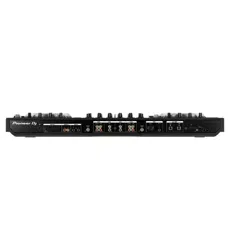
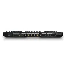
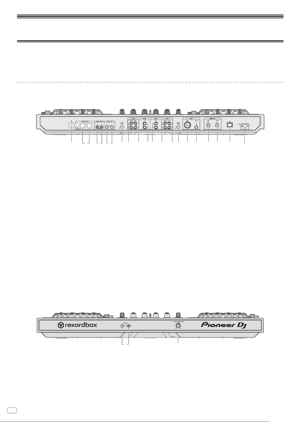
Rear panel
5 5
3 9 db c e6 7 6 7 a2 4881
1 Kensington security slot
2 MASTER OUT 1 terminals
Connect powered speakers, etc., here.
! Compatible with XLR connector type balanced outputs.
3 MASTER OUT 2 terminals
Connect to a power amplifier, etc.
! Compatible with RCA pin-jack type unbalanced outputs.
4 BOOTH OUT terminals
Output terminals for a booth monitor, compatible with balanced or unbalanced
output for a TRS connector.
The master channel sound can be output from the [BOOTH OUT] terminals
regardless of the audio level set for the master channel.
The volume level can be adjusted with the [BOOTH MONITOR] control.
! The sound will be distorted if the level is raised too high when using unbal-
anced outputs.
5 SIGNAL GND terminal
Connects an analog player’s ground wire here. This helps reduce noise when the
analog player is connected.
6 PHONO terminals
Connect to a phono level (MM cartridge) output device. Do not input line level
signals.
!
You need to set the [LINE, PHONO, USB] selector switch on top of the unit to
[PHONO] beforehand.
7 LINE terminals
Connect to a DJ player or other line level device.
! You need to set the [LINE, PHONO, USB] selector switch on top of the unit to
[LINE] beforehand.
8 CD terminals
Connect to a DJ player or other line level device.
! You need to set the [CD, USB] selector switch on top of the unit to [CD]
beforehand.
9 MIC1 terminal
Connects a microphone here.
! Either an XLR connector or a phones plug (Ø 6.3 mm) can be used.
a MIC2 terminal
Connects a microphone here.
b USB-B terminal
Connect to a computer.
! Connect this unit to your computer directly via a USB cable included with
this product or the one that conforms to USB 2.0.
! A USB hub cannot be used.
c USB-A terminal
Connect to a computer.
! Connect this unit to your computer directly via a USB cable included with
this product or the one that conforms to USB 2.0.
! A USB hub cannot be used.
d u switch
This switches this unit’s power between on and standby.
e AC IN terminal
Connect the power cord after all the connections between devices have been
completed.
Be sure to use the included power cord.
Front panel
12
1 PHONES jacks
Connect headphones here.
Both stereo phone plugs (Ø 6.3 mm) and stereo mini phone plugs (Ø 3.5 mm)
can be used.
! There are two input jacks, both a stereo phones jack and a mini phones jack,
but do not use both simultaneously. If both are used simultaneously, when
one is disconnected and/or connected, the volume of the other may increase
or decrease suddenly.
2 CROSS FADER CURVE selector switch
This switches the crossfader curve characteristics.
! The further the control is turned clockwise, the sharper the curve rises.
! The further the control is turned counterclockwise, the more gradually the
curve rises.
En
7
Connections and part names
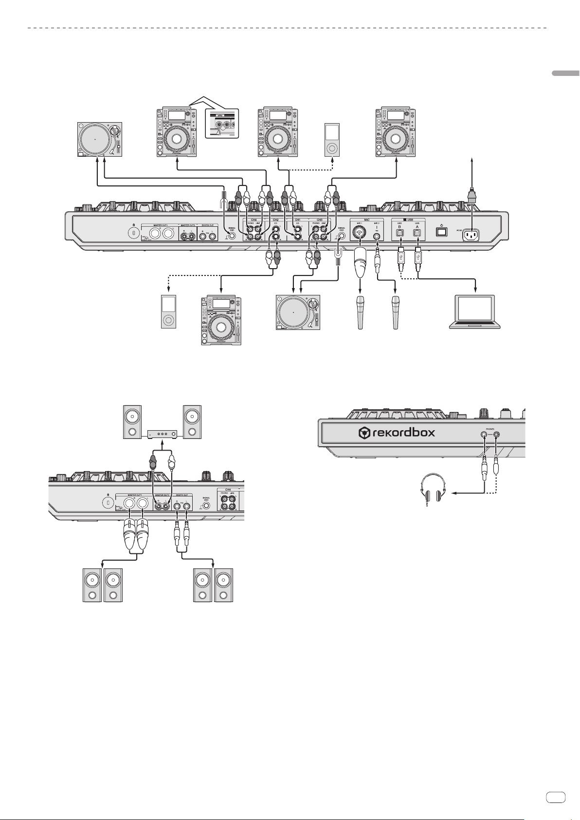
Connecting the input/output terminals
Connecting input terminals
Rear panel
AUDIO OUT
RL
CON
T
R
L
R
L
R
L
R
L
R
L
R
L
Analog player
Analog player
Microphone Microphone Computer
DJ player
DJ player
DJ player DJ player
To power outlet
Power cord
(included)
Portable audio
device
Portable audio
device
Connecting output terminals
Rear panel
R
L
Component, amplifier,
powered speaker, etc.
Power amplifier,
powered speakers, etc.
Power amplifier (for booth monitor),
powered speakers, etc.
Front panel
Headphones
En
8
Part names and functions
1 Browser section
2 Deck section
3 Mixer section
4 Effect section
Browser section
1
3
2
1 Rotary selector
Turn:
Moves the selection cursor in the DJ application.
[SHIFT] + turn:
Enlarges or reduces the enlarged waveform display of rekordbox dj.
Right turn enlarges the waveform display, and left turn reduces it.
Press:
Moves between the tree view area and track list area of rekordbox dj.
[Tree View] l [Track] list l [Tree View] l ...
! When [Tag List], [Palette bank1], and [Related Tracks] are displayed, also
moves between these areas.
[SHIFT] + press:
Registers or unregisters the selected track to/from [Tag List].
2 BACK button
Press:
Moves between the tree view and track list or opens and closes a folder.
[SHIFT] + press:
Changes the display depending on the state in [rekordbox dj] as shown below.
No display l [Tag List] displayed l [Palette bank1] displayed l [Palette
bank2] displayed l [Palette bank3] displayed l No display l …
Also, when [Tag List] is displayed, the cursor moves to the [Tag List] area.
3 LOAD (RELATED TRACKS) button
Press:
Loads the selected track to the deck.
Press twice:
Loads the track loaded in the deck not being operated to the deck on the opera-
tion side.
The playback position is also loaded in the same state.
[SHIFT] + press:
Displays [Related Tracks] if hidden and hides it if displayed.
No display l [Related Tracks] displayed l No display l …
Also, when [Related Tracks] is displayed, the cursor moves to the
[Related Tracks] area.
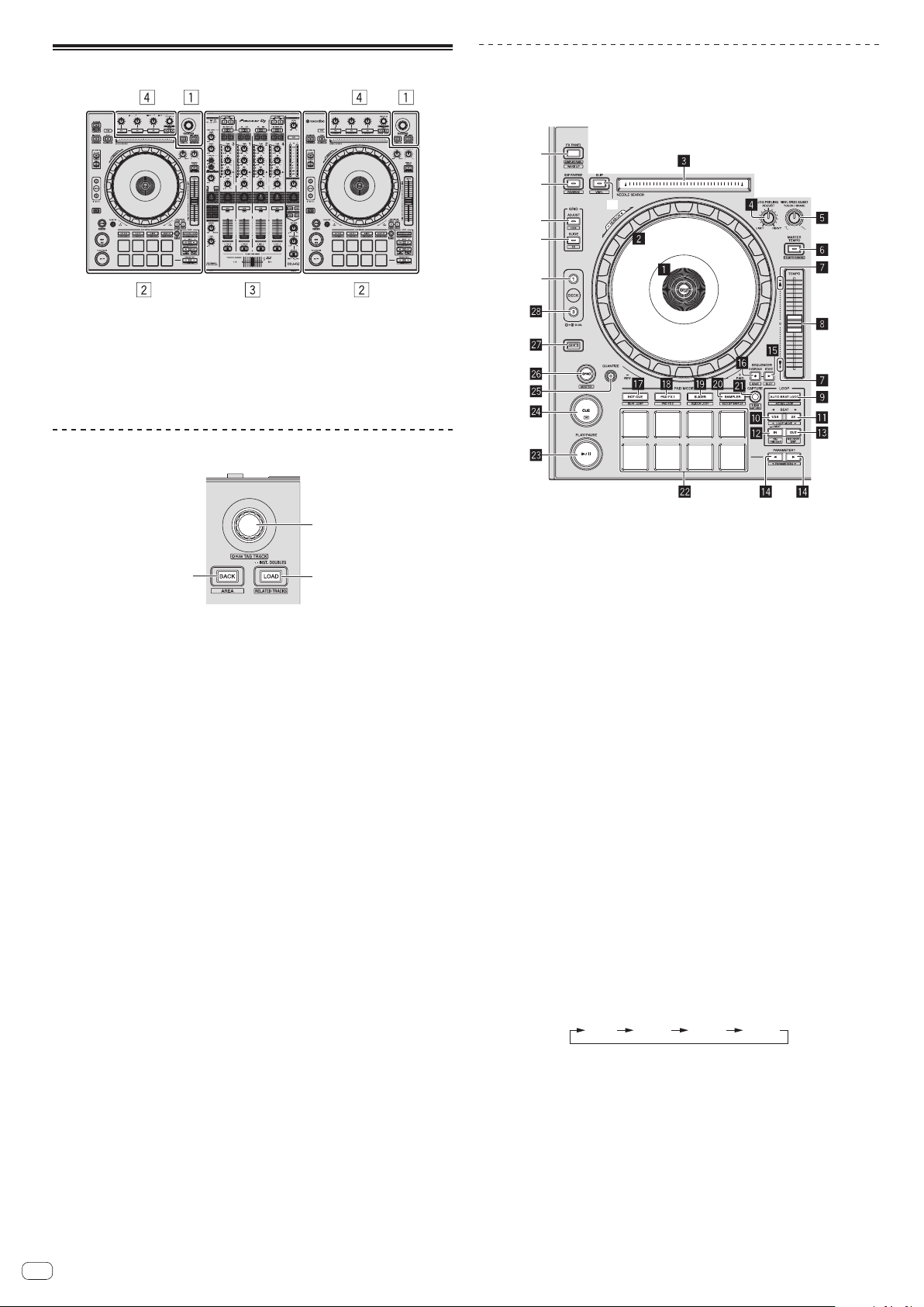
Deck section
This section is used to control the four decks. The buttons and controls for operating
decks 1 and 3 are located on the left side of the controller, those for operating decks
2 and 4 are located on the right side of the controller.
t
u
v
x
y
w
1 Jog dial display section
= Jog dial display section (p. 12 )
2 Jog dial
Turn top when VINYL mode is on:
Performs scratching operation.
Turn outer section or turn top when VINYL mode is off:
The pitch bend operation (adjustment of the playing speed) is possible.
[SHIFT] + Turn top:
Fast-forwards or fast-reverses.
3 NEEDLE SEARCH pad
By touching the pad, you can jump to the desired playback position in the track
loaded in the deck.
! In the environmental settings of rekordbox, you can set to enable to jump to
the desired playback position during pause or anytime.
4 JOG FEELING ADJUST control
This adjusts the load applied when the jog dial is spun.
The load gets heavier when turned clockwise, lighter when turned
counterclockwise.
5 VINYL SPEED ADJUST TOUCH/BREAK control
Adjusts the speed at which playback is slowed to the stopped state when the
stop operation is performed during playback.
6 MASTER TEMPO button
Press:
Turns the master tempo function on or off.
When the master tempo function is on, the key does not change even when the
playback speed is changed with the [TEMPO] slider.
[SHIFT] + press:
The [TEMPO] slider’s range of variation switches each time the button is
pressed.
[
±6%
][
±10%
][
±16%
][
WIDE
]
7 Takeover indicator
When decks are switched, the sync function is off, or the master is switched
while synchronizing, the position of the controller’s [TEMPO] slider may not
match the software’s tempo (pitch). To regain control of the tempo from the
controller, adjust using the takeover indicator as reference. Slowly move the
[TEMPO] slider in the direction in which the takeover indicator lights. When
moved to the position at which the takeover indicator turns off, it matches the
software’s tempo (pitch) and the tempo can once again be controlled with the
[TEMPO] slider.
8 TEMPO slider
Use this to adjust the track playing speed.

En
9
Connections and part names
9 AUTO BEAT LOOP button
Press:
Turns manual loop and auto beat loop on or off.
[SHIFT] + press:
The loop registered in [rekordbox] can be set as the active loop.
Setting an active loop
! If pressing the [SHIFT] and [AUTO BEAT LOOP] buttons when a loop is reg-
istered in rekordbox and a track for which an active loop is not set is loaded,
the closest loop in a clockwise direction can be set as an active loop.
!
The function is invalid when a track which a loop is not registered to is loaded.
Canceling the active loop setting
! If pressing the [SHIFT] and [AUTO BEAT LOOP] buttons when a track for
which an active loop is set is loaded, the set active loop can be canceled.
a LOOP 1/2X button
Press:
Select the auto loop beat.
During loop playback, the length of loop playback is split in half each time this
button is pressed.
[SHIFT] + press:
During loop playback, moves the loop to the left by the amount equal to its
length. (Loop Move)
b LOOP 2X button
Press:
Select the auto loop beat.
During loop playback, the loop length is doubled each time this button is
pressed.
[SHIFT] + press:
During loop playback, moves the loop to the right by the amount equal to its
length. (Loop Move)
c LOOP IN button
Press:
Loop In Point is set.
When this button is pressed during loop playback, the loop in point can be fine-
adjusted using the jog dial.
[SHIFT] + press:
Moves to the loop in point.
Press for over 1 second:
Starts 4-beat looping.
d LOOP OUT button
Press:
The loop out point is set, and loop playback begins.
When this button is pressed during loop playback, the loop out point can be fine-
adjusted using the jog dial.
[SHIFT] + press:
Cancels loop playback. (Loop Exit)
After loop playback is canceled, playback returns to the previously set loop in
point and loop playback resumes. (Reloop)
e PARAMETERc button, PARAMETERd button
These set the various parameters for when using the performance pads.
= Using the performance pads (p. 16 )
f SEQUENCER START button
Press:
Starts playback of the recorded performance information (sequence).
When this button is pressed again during playback of a sequence, the playback
pauses. When this button is pressed while recording a sequence, new sequence
is overdubbed onto the sequence being played back.
g SEQUENCER OVERDUB button
Press:
Turns the overdub function on.
Enters the standby state for recording and starts recording performance infor-
mation when a pad is operated.
[SHIFT] + press:
Saves the recorded performance information to the sequencer.
h HOT CUE mode button
Press:
Sets the hot cue mode.
= Using hot cues (p. 16 )
[SHIFT] + press:
Sets the beat jump mode.
=
Using beat jump (p. 16 )
i PAD FX1 mode button
Press:
Sets the pad FX1 mode.
= Using the pad FX (p. 16 )
[SHIFT] + press:
Sets the pad FX2 mode.
= Using the pad FX (p. 16 )
j SLICER mode button
Press:
Sets the slicer mode.
= Using the Slicer function (p. 16 )
[SHIFT] + press:
Sets the slicer loop mode.
= Using the Slicer function (p. 16 )
k SAMPLER mode button
Press:
Sets the sampler mode.
= Using the sampler function (p. 17 )
[SHIFT] + press:
Sets the velocity sampler mode.
= Using the velocity sampler (p. 18 )
l CAPTURE button
Press:
Registers the loop being played to the sampler pad.
! This is enabled when looping is in a set state.
[SHIFT] + press:
Loads the sections in the target area of slicer or slicer loop to separate sampler
slots.
! This is enabled in slicer mode or slicerUsing effects in the multi FX mod loop
mode.
! For detailed instructions on slicer and slicer loop, see the rekordbox soft-
ware’s manual.
m Performance pads
Various performances can be achieved using the pads.
= Using the performance pads (p. 16 )
n PLAY/PAUSE f button
Press:
Use this to play/pause tracks.
o CUE button
Press:
Sets, plays and calls out cue points.
! When the [CUE] button is pressed during pause, the cue point is set.
! When the [CUE] button is pressed during playback, the track returns to the
cue point and pauses. (Back Cue)
! When the [CUE] button is pressed and held after the track returns to the cue
point, playback continues as long as the button is pressed. (Cue Sampler)
[SHIFT] + press:
Returns to the beginning of the track.
p QUANTIZE button
Turns quantize on or off.
q SYNC button
Press:
Switches between synchronizing and not synchronizing (SYNC ON/OFF) to the
tempo of the master deck.
[SHIFT] + press:
Use this to set the track loaded in this unit as the master for the beat sync
function.
r SHIFT button
When another button is pressed while pressing the [SHIFT] button, a different
function is called out.
s DECK 3 button
Switches the deck to be operated to deck 3.
t DECK 1 button
Switches the deck to be operated to deck 1.
u GRID SLIDE button
Press:
When the jog dial is turned while pressing the [GRID SLIDE] button, the overall
beat grid can be slid to the left or right.
[SHIFT] + press:
Doubles the interval for beat grids.
En
10
v GRID ADJUST button
Press:
When the jog dial is turned while pressing the [GRID ADJUST] button, the beat
grid interval can be adjusted.
[SHIFT] + press:
Halves the interval for beat grids.
w SLIP button
Press:
Turns the slip mode on and off.
= Using the slip mode (p. 18 )
[SHIFT] + press:
This switches the vinyl mode on/off.
x SLIP REVERSE button
Press:
Performs reverse playback only while pressed.
Slip reverse play is automatically canceled after 8 beats have elapsed even if the
[SLIP REVERSE] button is kept pressed. The playback returns to normal after
reverting to the background.
[SHIFT] + press:
Switches between forward playback and reverse playback.
y FX PANEL button
Press:
(During normal operation)
Switches [FX] panel display.
(During standby status)
The standby mode is canceled.
[SHIFT] + press:
Displays or hides [SAMPLER] panel display.
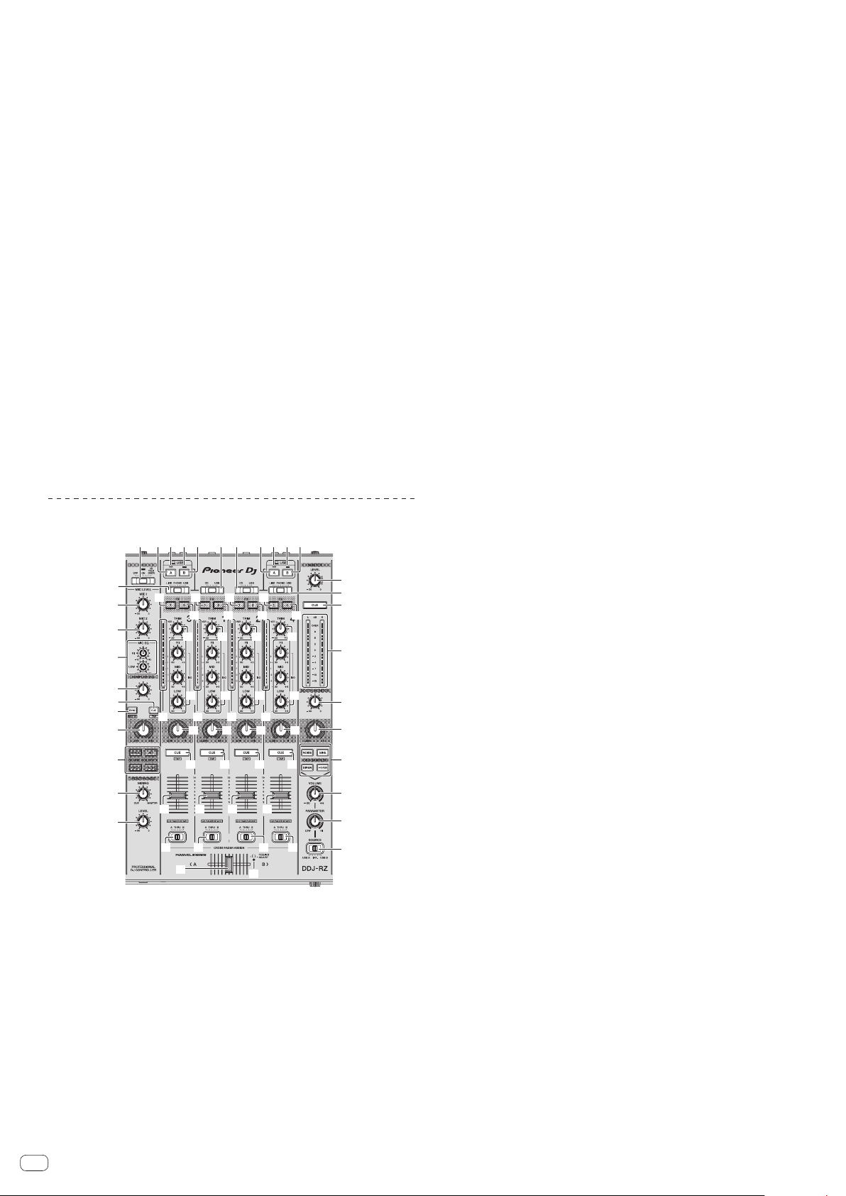
Mixer section
1 2 2 2 23 4 3 4
6
9
5
7
8
a
b
c
d
e
f
g
h
j
k
l
m
o
t t t t
i
x x x x
v
w w w w
v v v
y y
z
q
s s s s
n
r
q
r
q
r
q
r
p
p
o
u u u u
yy
A
1 OFF, ON, TALK OVER selector switch
Turns the microphone on/off.
2 USB connection indicator
Displays the connection status between the USB-A terminal and USB-B
terminal.
Lights: When the computer is connected to the terminal and the driver is
installed
Flashes: When the computer is connected to the terminal and the driver is not
installed
Lights out: When the computer is not connected to the terminal
3 USB (A) button
When lights, the USB-A terminal is used in communication with the computer.
! The [USB (A)] button and [USB (B)] button located at the left side are used to
control the USB communication for deck 1 or deck 3. The [USB (A)] button
and [USB (B)] button located at the right side are used to control USB com-
munication for deck 2 or deck 4.
! When the [USB (A)] button or [USB (B)] button located on the left side is
flashing, it means the deck 1 or deck 3 audio is on air. Flashing stops when
the channel fader of deck 1 or deck 3 is moved to the frontmost position.
When the [USB (A)] button or [USB (B)] button located on the right side is
flashing, it means deck 2 or deck 4 audio is on air. Flashing stops when the
channel fader of deck 2 or deck 4 is moved to the frontmost position. (When
the USB terminal is switched, sound is also switched instantaneously.
Therefore, when the button is flashing, before switching the USB terminal,
make sure that the deck is not used by another user.)
4 USB (B) button
When lights, the USB-B terminal is used in communication with the computer.
! The [USB (A)] button and [USB (B)] button located at the left side are used to
control the USB communication for deck 1 or deck 3. The [USB (A)] button
and [USB (B)] button located at the right side are used to control USB com-
munication for deck 2 or deck 4.
! When the [USB (A)] button or [USB (B)] button located on the left side is
flashing, it means the deck 1 or deck 3 audio is on air. Flashing stops when
the channel fader of deck 1 or deck 3 is moved to the frontmost position.
When the [USB (A)] button or [USB (B)] button located on the right side is
flashing, it means deck 2 or deck 4 audio is on air. Flashing stops when the
channel fader of deck 2 or deck 4 is moved to the frontmost position. (When
the USB terminal is switched, sound is also switched instantaneously.
Therefore, when the button is flashing, before switching the USB terminal,
make sure that the deck is not used by another user.)
5 MASTER LEVEL control
Adjusts the master sound level output.
6 MASTER CUE button
Turns monitoring of the master output’s sound on and off.
7 Master level indicator
Displays the master output’s audio level.
8 BOOTH MONITOR control
Adjusts the level of audio signals output from the [BOOTH OUT] terminal.
9 MASTER OUT COLOR control
Changes the SOUND COLOR FX parameter applied to the master output sound.
a OSC SAMPLER SELECT button
Generates oscillator sound (NOISE, SINE, SIREN, and HORN).
=
Using the oscillator function (p. 22 )
b OSC SAMPLER VOLUME control
Adjusts the sound level of oscillator sound.
c OSC SAMPLER PARAMETER control
Adjusts the quantitative parameters of oscillator sound.
d SOURCE selector switch
Selects the oscillator sound source.
e HEADPHONES LEVEL control
Adjusts the sound level output from the headphones.
f HEADPHONES MIXING control
Adjusts the balance of the monitor volume between the sound of the channels
for which the headphones [CUE] button is pressed and the sound of the master
channel.
g SOUND COLOR FX buttons
These turn the SOUND COLOR FX effects on/off.
h MIC COLOR control
Changes the parameter of SOUND COLOR FX applied to microphone sound or
sampler sound.
i SAMPLER SYNC button
Press:
Switches between synchronizing and not synchronizing (SYNC ON/OFF) the
sampler sound to the tempo of the master deck.
[SHIFT] + press:
Sets the sampler sound source as the master for the beat sync function.
j SAMPLER CUE button
Press:
Turns monitoring of the sampler sound on or off.
[SHIFT] + press:
Calculates the BPM value used as the base for the sampler from the interval at
which the button is tapped with a finger. (Tap function)
En
11
Connections and part names
k SAMPLER VOLUME control
Adjusts the sound level of sampler.
l EQ (HI, LOW) controls
These adjust the tone quality of the [MIC1] and [MIC2] channels.
m MIC2 control
Adjusts the sound level output from the [MIC2] channel.
n MIC1 control
Adjusts the sound level output from the [MIC1] channel.
o CD, USB selector switch
Selects the input source of each channel from the components connected to
this unit.
! [CD]: Select this to use a line level output device (DJ player, etc.) connected
to the [CD] terminals.
! [USB]: Select this to use the track loaded in the rekordbox dj deck.
p LINE, PHONO, USB selector switch
Selects the input source of each channel from the components connected to
this unit.
! [LINE]: Select this to use a line level output device (DJ player, etc.) connected
to the [LINE] input terminals.
— When [PHONO] is selected, sound is muted momentarily.
! [PHONO]: Select this to use a phono level (for MM cartridges) output device
(analog player, etc.) connected to the [PHONO] input terminals.
! [USB]: Select this to use the track loaded in the rekordbox dj deck.
q FX 1 assign button
Turns effect unit FX1 on and off for the respective channel.
r FX 2 assign button
Turns effect unit FX2 on and off for the respective channel.
s Channel Level Indicator
Displays the sound level of the respective channels before passing through the
channel faders.
t TRIM control
Adjusts the level of audio signals input in each channel.
u ISO (HI, MID, LOW) controls
Boosts or cuts frequencies for the different channels.
v COLOR control
This changes the parameters of the SOUND COLOR FX of the different channels.
w Headphones CUE button
Press:
The sound of channels for which the headphones [CUE] button is pressed is
output to the headphones.
! When the headphones [CUE] button is pressed again, monitoring is
canceled.
[SHIFT] + press:
The track’s tempo can be set by tapping the button. (Tap function)
x Channel fader
Move:
Adjusts the level of audio signals output in each channel.
[SHIFT] + move:
Use the channel fader start function.
= Using the channel fader start function (p. 19 )
y Crossfader assign selector switch
Assigns the channel output to the crossfader.
[A]: Assigns to [A] (left) of the crossfader.
[B]: Assigns to [B] (right) of the crossfader.
[THRU]: Selects this when you do not want to use the crossfader. (The signals do
not pass through the crossfader.)
z Crossfader
Outputs the sound assigned with the crossfader assign switch.
[SHIFT] + move:
Uses the crossfader start function.
= Using the crossfader start function (p. 20 )
A FEELING ADJUST adjustment hole
This can be used to adjust the crossfader’s operating load.
= Adjusting the crossfader’s operating load (p. 20 )
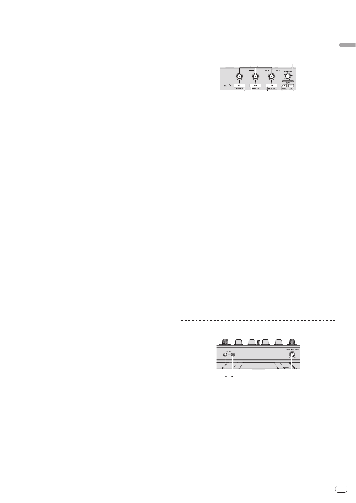
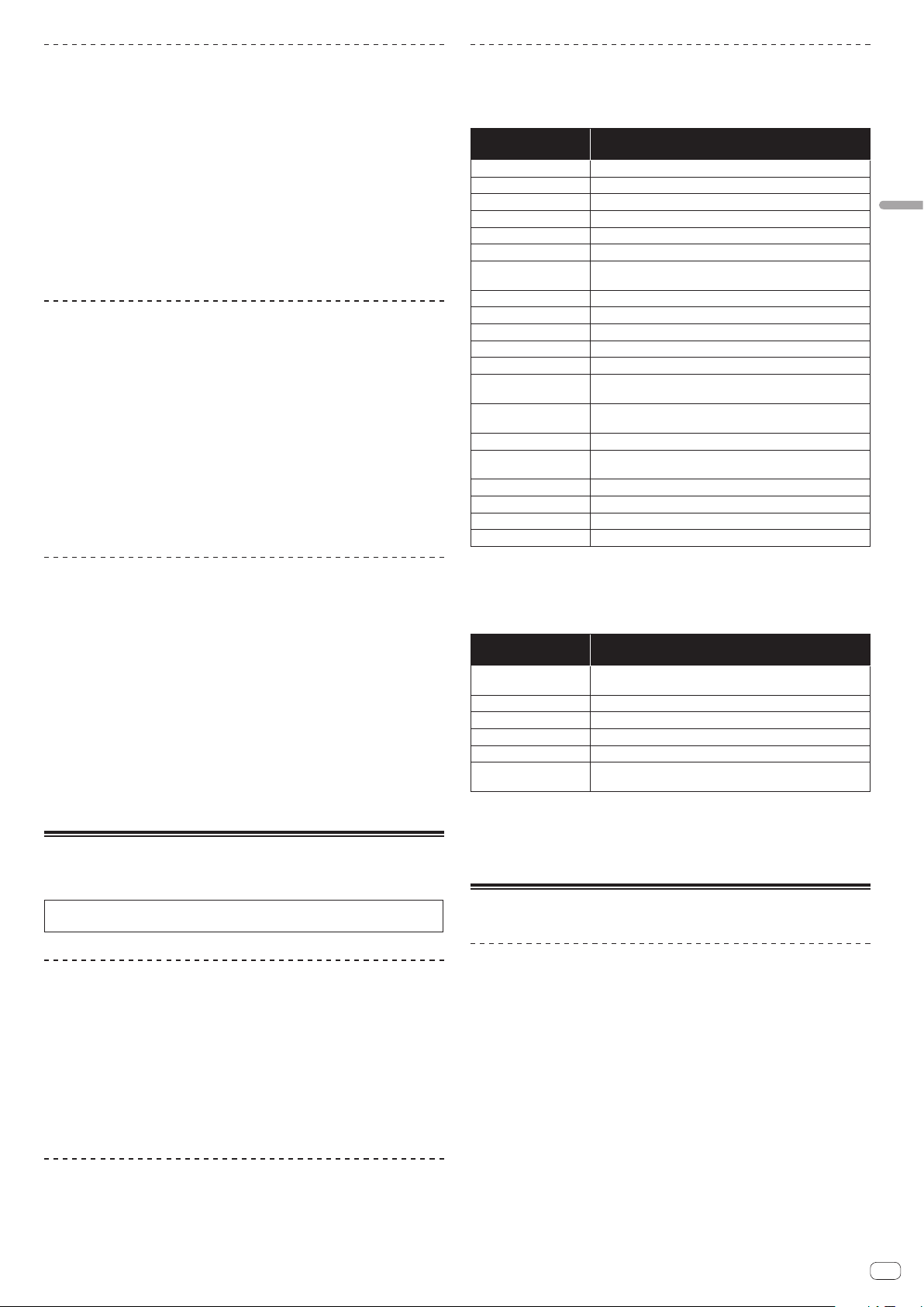
Effect section
This section is used to control the two effect units (FX1 and FX2). Controls and but-
tons used to operate the FX1 unit are located on the left side of the controller, those
used to operate the FX2 unit are located on the right side of the controller. The chan-
nels to which the effect is to be applied are set using the effect assign buttons on
the mixer.
21
3 4
1 Effect parameter controls
Adjusts the beat FX parameter.
2 RELEASE FX control
Turn:
Selects the release FX type.
Press:
Enables release FX only while pressed. If the release FX turns on, the beat FX in
the same effect unit turns off.
[SHIFT] + turn:
Adjusts the beat FX time.
[SHIFT] + press:
Switches the beat FX mode.
3 Effect parameter buttons
Press:
Turns the beat FX on and off or switches the parameters.
[SHIFT] + press:
Switches the effect type.
4 BEATc button, BEATd button
BEATc button
Press:
Reduces the beat interval for applying beat FX.
[SHIFT] + press:
Returns the tempo of beat FX to BPM of the deck.
BEATd button
Press:
Increases the beat interval for applying beat FX.
[SHIFT] + press:
Calculates the BPM value used as the base for beat FX from the interval at which
the button is tapped with a finger. (Tap function)
Front panel
12
1 PHONES jacks
2 CROSS FADER CURVE selector switch
This switches the crossfader curve characteristics.
! The further the control is turned clockwise, the sharper the curve rises.
! The further the control is turned counterclockwise, the more gradually the
curve rises.

En
12
Jog dial display section
1
2
3
4
1 Operation display
This works in synchronization with the rotation display of the rekordbox dj deck.
2 Cue point display
Displays the cue point.
! You can switch between the current cue display and hot cue countdown
display in the environment settings of rekordbox.
3 Jog touch detection display
The display lights when the jog dial top is pressed when VINYL mode is on.
4 VINYL
The display lights when VINYL mode is on.
En
13
Basic Operation
Basic Operation
Connecting this unit and computer
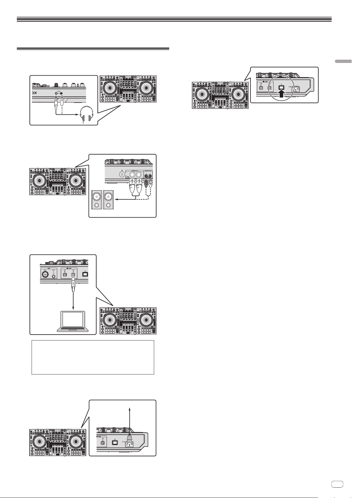
1 Connect headphones to one of the [PHONES] terminals.
2 Connect powered speakers, a power amplifier,
components, etc., to the [MASTER OUT 1] or [MASTER OUT 2]
terminals.
Powered speaker, etc.
! To output the sound from the [BOOTH OUT] terminals, connect speakers or
other devices to the [BOOTH OUT] terminals.
! For details on the connections of the input/output terminals, see Connections
(p. 6 ).
3 Connect this unit to your computer via a USB cable.
USB cable
(included)
This product satisfies electromagnetic noise
regulations when it is connected to other equipment
through shielded cables and connectors.
Use only the furnished accessory connecting cables.
D44-8-2_A1_En
4 Turn on the computer’s power.
5 Connect the power cord.
Power cord
(included)
To power outlet
6 Press the [u] switch on this unit’s rear panel to turn this
unit’s power on.
Turn on the power of this unit.
! For Windows users
The message [Installing device driver software] may appear when this unit is
first connected to the computer or when it is connected to a different USB port
on the computer. Wait a while until the message [Your devices are ready for
use] appears.
7 Turn on the power of the devices connected to the output
terminals (powered speakers, power amplifier, components,
etc.).
! When a microphone, DJ player or other external device is connected to input
terminals, the power of that device also turns on.
En
14
Starting the system
Launching rekordbox
For Windows 7
Click the [All Programs] > [Pioneer] > [rekordbox] icon from the Windows [Start] menu.
For Windows 8.1/8
From [Apps view], click the [rekordbox] icon.
For Mac OS X
Open the [Applications] folder in Finder, then double-click the [rekordbox] icon.
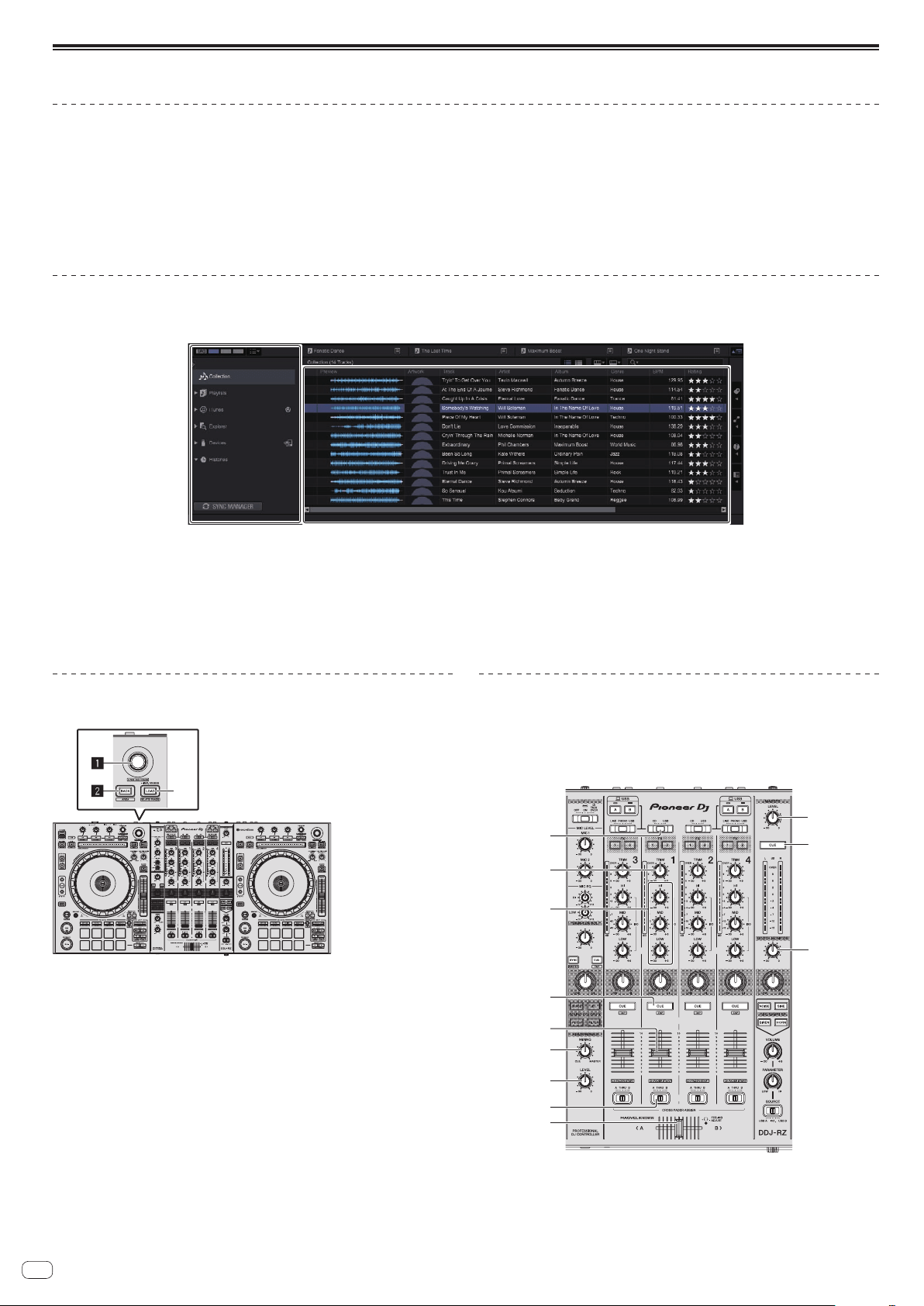
Adding music files to Collection
“Collection” is a list of all the tracks managed by rekordbox.
The music files on the computer can be used with rekordbox if they are analyzed and then registered as rekordbox music collection files.
Tree View
Track list
a
b
1 Click [Collection] in the tree view.
The [Collection] music files are displayed in the track list.
2 Open Finder or Windows explorer, then drag and drop music files or folders including music files to the track list.
The music files are added to the [Collection] and the tag information of the music files is read and then displayed.
This manual consists mainly of explanations of functions of this unit as hardware. For detailed instructions on operating rekordbox dj, see the rekordbox software’s manual.
Loading tracks and playing them
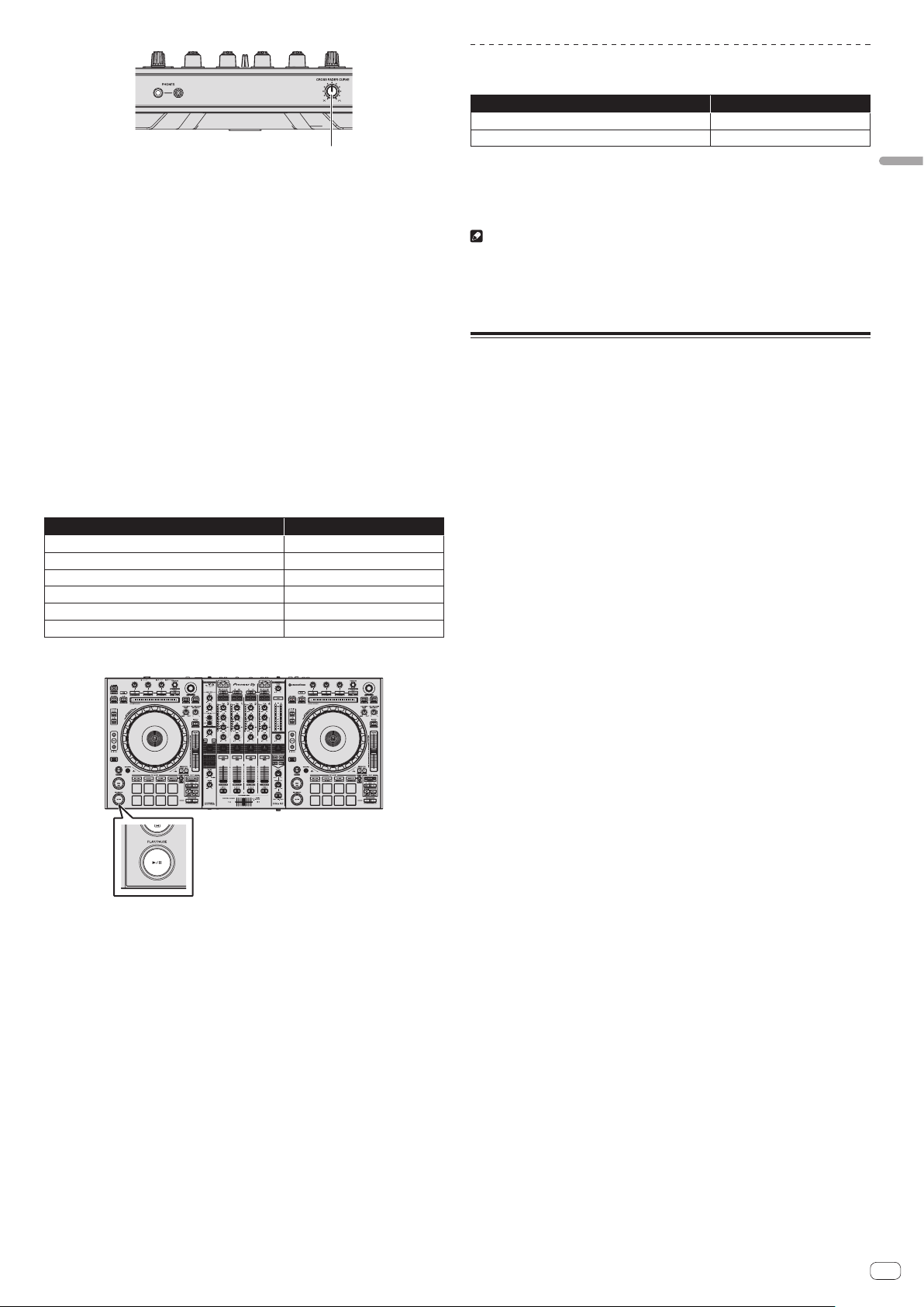
The following describes the procedure for loading tracks onto deck 1 as an example.
3
1 Rotary selector
2 BACK button
3 LOAD button
1 Select the [Collection] or a playlist or other item and then
press the unit’s rotary selector to move to the track list.
2 Turn the rotary selector and select the track.
3 Press the [DECK1] button.
4 Press the [LOAD] button to load the selected track onto the
deck.
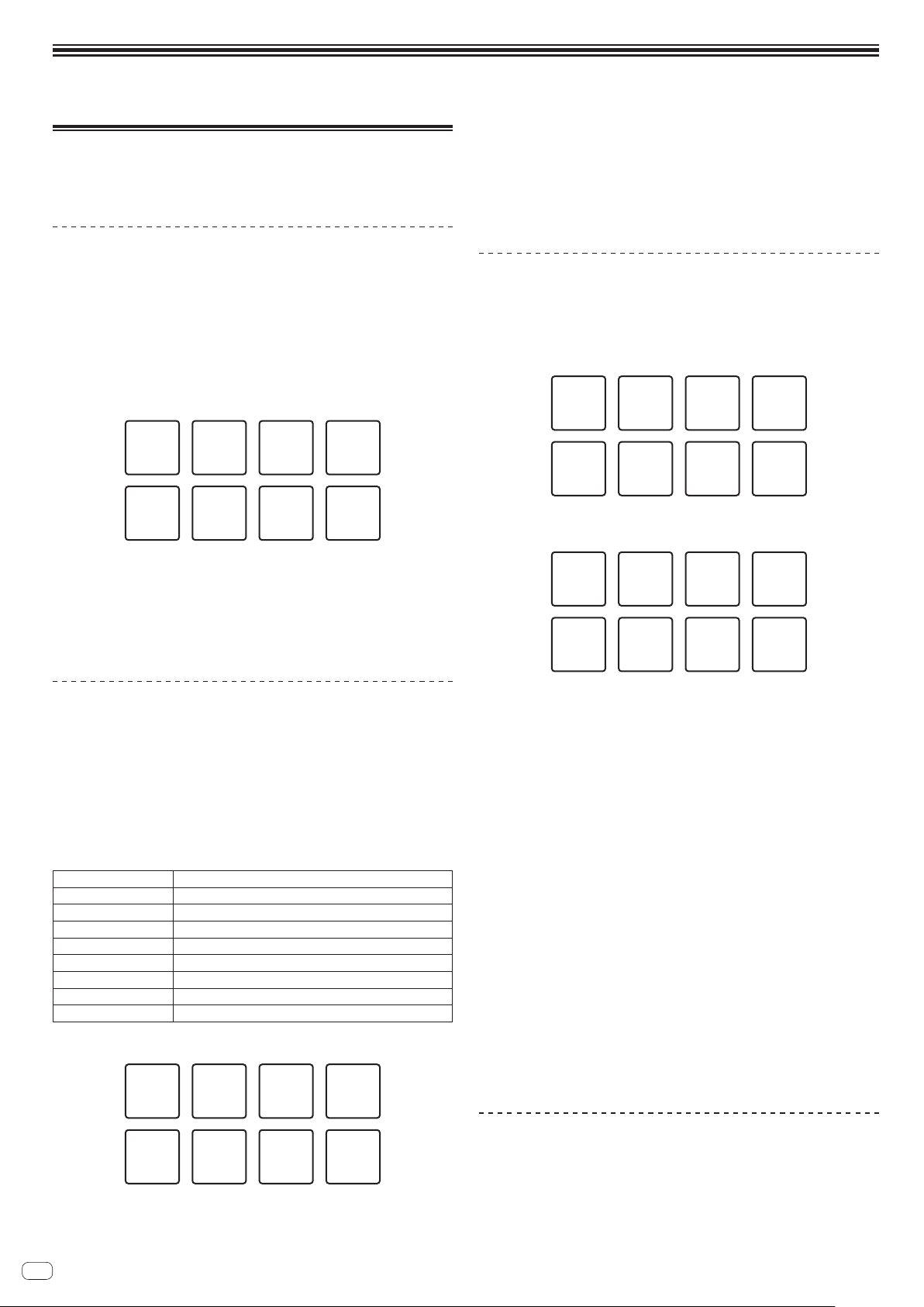
Playing tracks and outputting the sound
The following describes the procedure for outputting the channel 1 sound as an
example.
! Set the volume of the devices (power amplifier, powered speakers, etc.) con-
nected to the [MASTER OUT 1] and [MASTER OUT 2] terminals to an appropri-
ate level. Note that loud sound will be output if the volume is set too high.
d
4
8
7
5
6
9
a
b
c
e
f
En
15
Basic Operation
g
4 CD, USB selector switch
5 TRIM control
6 ISO (HI, MID, LOW) controls
7 Headphones CUE button
8 Channel fader
9 HEADPHONES MIXING control
a HEADPHONES LEVEL control
b Crossfader assign selector switch
c Crossfader
d MASTER LEVEL control
e MASTER CUE button
f BOOTH MONITOR control
g CROSS FADER CURVE control
1 Set the positions of the controls, etc., as shown below.
Names of controls, etc. Position
MASTER LEVEL control Turned fully counterclockwise
CD, USB selector switch [USB] position
TRIM control Turned fully counterclockwise
ISO (HI, MID, LOW) controls Center
Channel fader Moved forward
Crossfader assign selector switch [THRU] position
2 Press the [f] button to play the track.
3 Turn the [TRIM] control.
Adjust the [TRIM] control so that the channel level indicator’s orange indicator
lights at peak level.
4 Move the channel fader away from you.
5 Turn the [MASTER LEVEL] control to adjust the audio level
of the speakers.
Adjust the sound level output from the [MASTER OUT 1] and [MASTER OUT 2]
terminals to an appropriate level.
Monitoring sound with headphones
Set the positions of the controls, etc., as shown below.
Names of controls, etc. Position
HEADPHONES MIXING control Center
HEADPHONES LEVEL control Turned fully counterclockwise
1 Press the headphones [CUE] button for the channel 1.
2 Turn the [HEADPHONES LEVEL] control.
Adjust the sound level output from the headphones to an appropriate level.
Note
This unit and rekordbox dj include many functions to allow for more individu-
alistic DJ performances. For details on each function, see the rekordbox soft-
ware’s manual.
! The rekordbox software’s manual can be downloaded from rekordbox.com. For
details, see Downloading the rekordbox software manual (p. 29 ).
Quitting the system
1 Quit rekordbox.
2 Press the [u] switch on this unit’s rear panel to set this
unit’s power to standby.
3 Disconnect the USB cable from your computer.
En
16
Advanced Operation
Using the performance pads
Use the performance pads with the hot cue, beat jump, pad FX, slicer, sampler, and
velocity sampler functions.
The function of the performance pads can be switched with the pad mode buttons.
Using hot cues
This function allows playback to be started instantaneously from the position at
which a hot cue or hot loop is set.
! Up to eight hot cue points or hot loop points can be set and saved per track.
1 Press the [HOT CUE] mode button.
Switches to hot cue mode.
2 In the play or pause mode, press a performance pad to set
the hot cue point.
The hot cue points are assigned to the respective performance pads as shown
below.
Hot cue 1 Hot cue 2 Hot cue 3 Hot cue 4
Hot cue 5 Hot cue 6 Hot cue 7 Hot cue 8
A hot loop can be assigned to a performance pad by pressing the pad during loop
playback.
3 Press the performance pad with the hot cue point or hot
loop point set.
Playback starts from the hot cue point or hot loop point.
! Set hot cue points can be cleared by pressing a performance pad while
pressing the [SHIFT] button.
Using beat jump
The playback position can be moved instantaneously without breaking the rhythm of
the track being played back.
1 Press the [HOT CUE] mode button while pressing the
[SHIFT] button.
The mode switches to the beat jump mode.
2 Press the [PARAMETERc] or [PARAMETERd] button.
The movement amount (number of beats or number of bars) of the playback position
assigned to the performance pad changes each time a button is pressed.
The following nine settings can be made.
page1
FINE/1/8 beat/1/4 beat/1/2 beat
page2
1/8 beat/1/4 beat/1/2 beat/1 beat
page3
1/4 beat/1/2 beat/1 beat/2 beats
page4
1/2 beat/1 beat/2 beats/4 beats
page5
1 beat/2 beats/4 beats/8 beats
page6
2 beat/4 beats/8 beats/16 beats
page7
4 beats/8 beats/16 beats/8 bars
page8
8 beats/16 beats/8 bars/16 bars
page9
16 beats/8 bars/16 bars/32 bars
For example, when set to “1 beats from 1/8 beat”, the pad’s setting is as shown
below.
1/8 beat
(reverse
direction)
1/2 beat
(reverse
direction)
1/2 beat
(forward
direction)
1 beat
(reverse
direction)
1 beat
(forward
direction)
1/8 beat
(forward
direction)
1/4 beat
(reverse
direction)
1/4 beat
(forward
direction)
! If a button is pressed while pressing [SHIFT], only [page1], [page5], and
[page9] can be selected.
3 Press pad 1, pad 3, pad 5, or pad 7.
The playback position moves in the reverse direction by the number of beats or
number of bars assigned to the pad that was pressed.
4 Press pad 2, pad 4, pad 6, or pad 8.
The playback position moves in the forward direction by the number of beats or
number of bars assigned to the pad that was pressed.
Using the pad FX
A wide range of effect performances are possible with just the simple operation of
pressing and releasing performance pads.
1 Press the [PAD FX1] mode button.
The mode switches to pad FX mode 1.
By default, effects are assigned to the performance pads as shown below.
①
Slip
looping
(1/8 beat)
⑤
Delay
⑥
Filter LFO
⑦
Reverber
ation
⑧
Release
FX
②
Slip
looping
(1/4 beat)
③
Slip
looping
(1/2 beat)
④
Slip
looping
(1 beat)
! If the [PAD FX1] mode button is pressed while pressing the [SHIFT] button, the
mode changes to FX mode 2.
By default, effects are assigned to the performance pads as shown below.
①
Trance
(1/8 beat)
⑤
Pitch
⑥
Crash
⑦
Noise
⑧
Release
FX
②
Trance
(1/4 beat)
③
Trance
(1/2 beat)
④
Trance
(1 beat)
! The effects assigned to performance pads can be customized. For details, see
the rekordbox software’s manual.
! The type of release FX assigned to pad 8 cannot be changed by turning the
unit’s [RELEASE FX] control.
To change the type of release FX assigned to pad 8, you need to make the
change in rekordbox dj. For details, see the rekordbox software’s manual.
2 Press and hold one of the performance pads.
The effect turns on according to the effect and number of beats settings assigned to
the pad that was pressed.
3 Press the [PARAMETER c] button or [PARAMETER d]
button while pressing the performance pad.
The number of beats setting for the effect temporarily increases or decreases.
! Depending on the type of effect, changing the setting may not be possible
even by pressing the button.
4 Release your finger from the performance pad.
The effect turns off.
Using the release FX of the pad FX
1 Press and hold one of performance pads 1 to 7.
The effect turns on according to the effect and number of beats settings assigned to
the pad that was pressed.
2 Press performance pad 8.
The pad FX effect that was on up until now turns off and the release FX effect is
added.
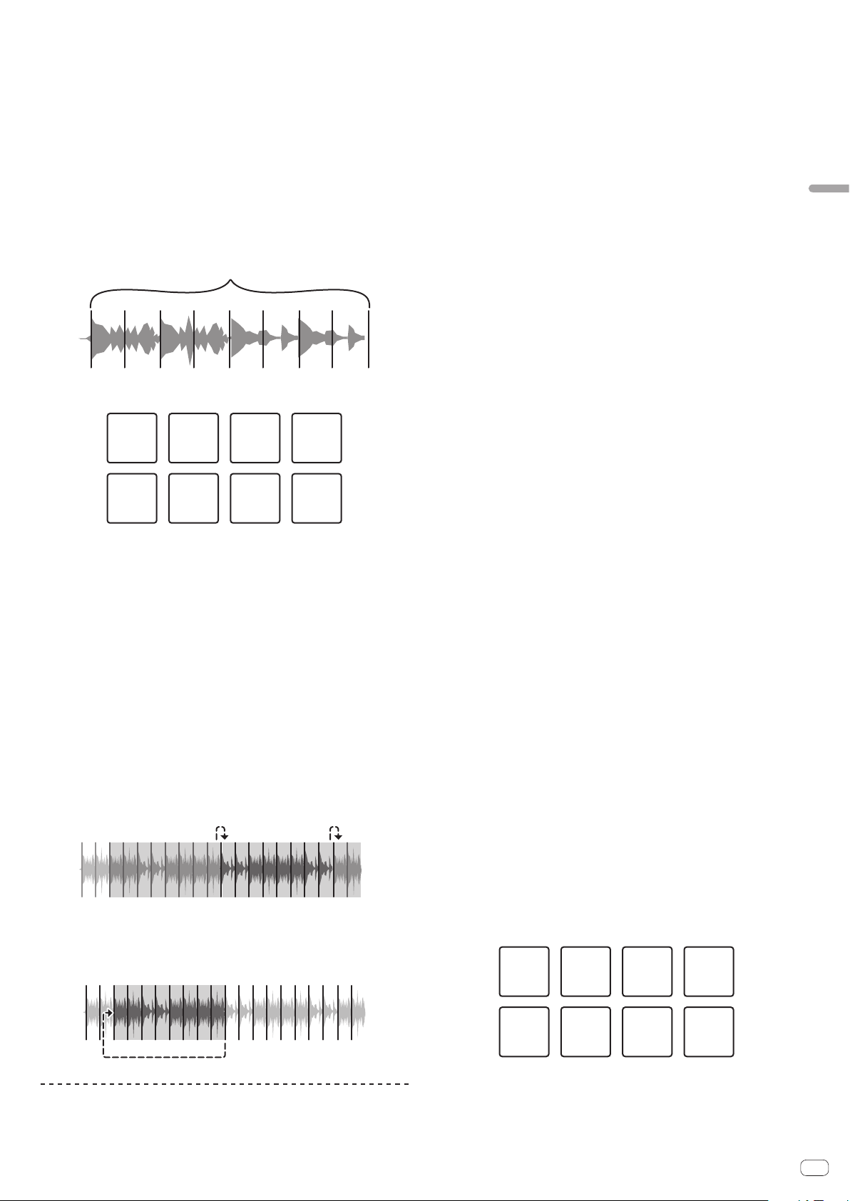
Using the Slicer function
The specified range is divided into eight equal sections, and these eight sliced
sections are assigned to the respective performance pads. While one of the perfor-
mance pads is pressed, the sound for the section assigned to that pad is played in
a loop.
During loop playback of the pad’s sound, normal playback with the original rhythm
continues in the background. When the pad is released and loop playback ends,
playback resumes from the position reached at that point.
En
17
Advanced Operation
! The slicer function cannot be used with tracks for which no beatgrid is set. For
details on setting beatgrids, see the rekordbox software manual.
— Beatgrids can also be set using this unit’s [GRID ADJUST] and [GRID SLIDE]
buttons. (p. 10 )
1 Press the [SLICER] mode button.
Switches to slicer mode.
! While pressing the [SHIFT] button, pressing the [SLICER] mode button switches
the mode to slicer loop mode.
! For details, see About slicer mode and slicer loop mode on page 17 .
2 Press the [PARAMETERc] or [PARAMETERd] button while
pressing the [SHIFT] button.
Set the slicer range. The slicer range changes each time a button is pressed while
pressing the [SHIFT] button.
Each of the sections resulting from dividing the slicer range into eight is assigned to
the respective performance pad as shown below.
Sliced sections 1 to 8
Domain
1234 56
78
Section 1 Section 2 Section 3 Section 4
Section 5 Section 6 Section 7 Section 8
3 Press the [PARAMETERc] or [PARAMETERd] button.
Set the loop playback length for the slicer. The setting value for the loop playback
length changes each time the button is pressed.
The length of loop playback while a pad is pressed can be changed with the loop
playback length setting. For example, when the loop playback length is set to “1”, the
entire section assigned to the pad is played in a loop, and when the loop playback
length is set to “1/2”, only the first half of the section assigned to the pad is played
in a loop.
4 Press and hold one of the performance pads.
When the pad is pressed and held, the sound is played in a loop.
When the pad is released, the track returns to the position that is playing in the
background.
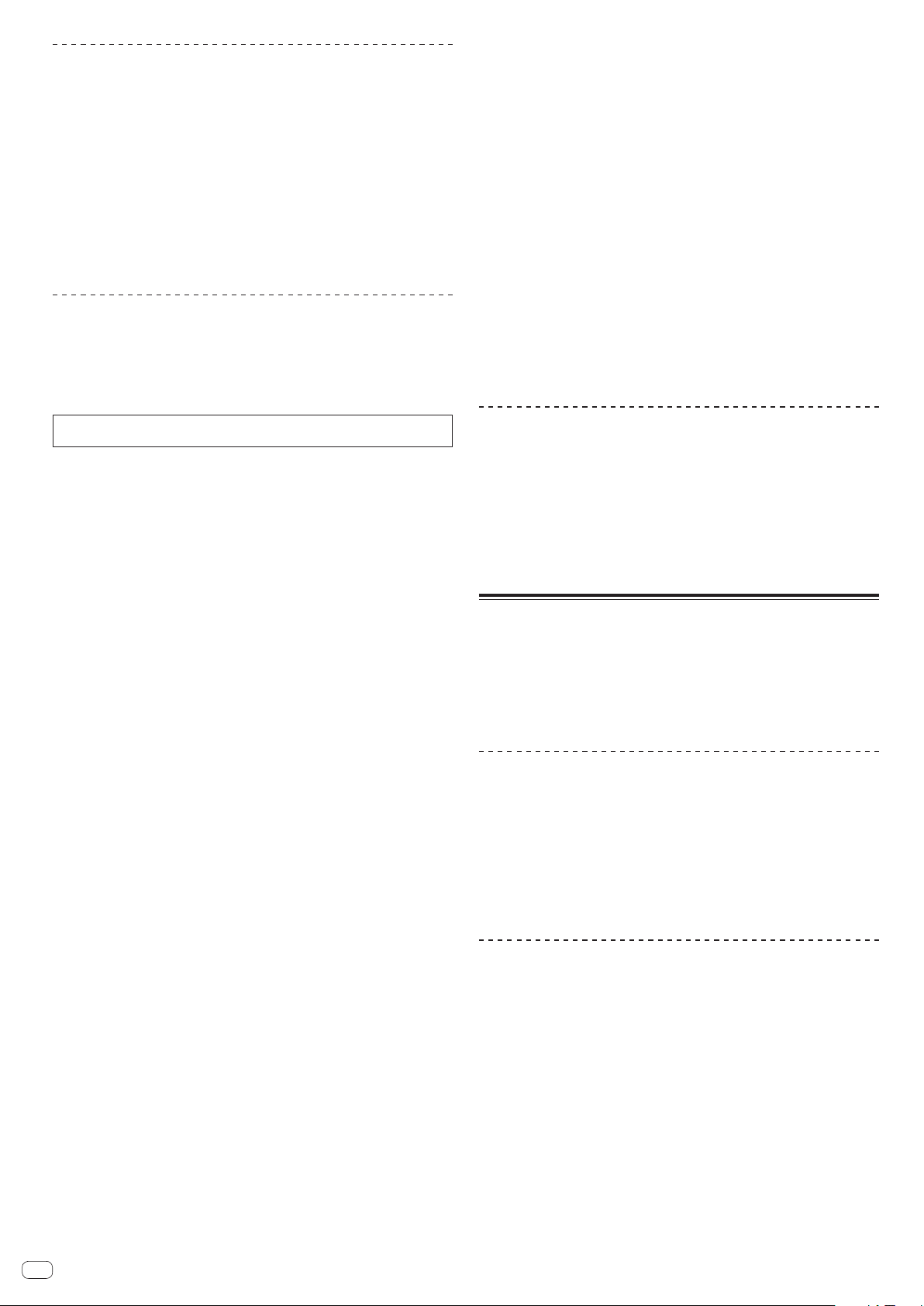
About slicer mode and slicer loop mode
Slicer mode
When the playback position advances to the end of the range that has been sliced
into eight equal sections, the range shown on the display switches to the next eight
sliced sections, and these sliced sections are assigned to the respective pads,
replacing the previously assigned sections.
12345678
11
2
2
…
345678
Slicer loop mode
When the playback position advances to the end of the range that was sliced into
eight equal parts, the playback position returns to the beginning of the range that
was sliced into eight equal parts.
12345678
Using the sampler function
This procedure can be used to play tracks loaded in the sampler’s sampler slots
using the performance pads.
Preparing to use the sampler
Press the [FX PANEL] button while pressing the [SHIFT] button.
The sampler panel appears on the rekordbox dj screen.
A track, loop, and slicer target area can be loaded in sampler slots.
Load the track in a sampler slot.
1 Press the [SAMPLER] mode button.
Switches to the sampler mode.
2 Press the rotary selector or [BACK] button to move the
cursor to the track list.
3 Turn the rotary selector.
Select the track you wish to load in a sampler slot.
4 Press the performance pad while pressing the [SHIFT]
button.
The selected track is loaded into the sample slot.
! Loading by overwriting an already loaded sampler slot may not be possible
depending on the preferences of rekordbox.
Loading a loop in a sampler slot.
1 Press the [AUTO BEAT LOOP] button or [LOOP IN] button
and then press the [LOOP OUT] button.
Loop playback starts.
2 Press a performance pad while pressing the [CAPTURE]
button.
The pad mode is temporarily switched to the sampler mode and the loop is loaded in
a sampler slot.
! Loading by overwriting an already loaded sampler slot may not be possible
depending on the preferences of rekordbox.
Loading the slicer target area in sampler slots
1 Press the [SLICER] mode button while pressing the [SHIFT]
button.
The mode switches to the slicer loop mode.
!
Alternatively, press the [SLICER] mode button to switch to the slicer mode.
2 Press the [CAPTURE] button while pressing the [SHIFT]
button.
Each of the sections of the slicer target area is loaded in a separate sampler slot.
! With the default settings of rekordbox, the slicer target area is loaded in
sampler bank 4.
If there is even one sampler slot already loaded in sampler bank 4, loading
may not be possible.
Using the performance pads to play the sampler
1 Press the [SAMPLER] mode button.
Switches to the sampler mode.
2 Press the [PARAMETERc] or [PARAMETERd] button.
The sampler bank is switched. The sampler has four banks and each bank has
sixteen slots.
3 Turn the [SAMPLER VOLUME] control clockwise.
4 Press a performance pad.
The sound for the slot assigned to the pad that was pressed is played.
! When the pad mode of deck 1 or deck 3 is the sampler mode (the slots in paren-
theses are when the pad mode of deck 2 or deck 4 is the sampler mode)
Slot 1
(slot 9)
Slot 2
(slot 10)
Slot 3
(slot 11)
Slot 4
(slot 12)
Slot 5
(slot 13)
Slot 6
(slot 14)
Slot 7
(slot 15)
Slot 8
(slot 16)
5 During playback, press a performance pad.
Playback continues by returning to the beginning.
6 Press a performance pad while pressing the [SHIFT] button
during playback.
The sound of the slot that is currently playing stops.
En
18
Using the velocity sampler
In the velocity sampler mode, the sample volume level changes according to the
amount of force used to tap the performance pads. The volume level increases when
the performance pads are tapped strongly and decreases when they are tapped
weakly.
Switching to the velocity sampler mode
When the [SAMPLER] mode button is pressed while pressing the [SHIFT] button, the
mode switches to the velocity sampler mode.
When the [SAMPLER] mode button is pressed, the mode switches to the normal
sampler mode.
!
The velocity curve can be set in the utilities mode.
For details, see Changing the velocity curve setting of velocity sampler mode on
page 25 .
Using the sequencer
Sampler performances can be recorded and played back.
The sequencer function can be used to achieve a variety of performances, such as
superimposing an original rhythm loop or vocal loop created in advance on the track
that is playing or changing the arrangement of an impromptu finger drum perfor-
mance by adding sound using the overdub recording function or removing and
adding sound using the mute function.
The following explains the basic operations of the sequencer. For sequencer
application examples, see the rekordbox software’s manual.
Preparing to use the sequencer
1 Press the [FX PANEL] button while pressing the [SHIFT]
button.
The sampler panel appears on the rekordbox dj screen.
2 Press the [SAMPLER] mode button.
The unit’s pad mode switches to the sampler mode.
Recording a sequence
1 Press the [PARAMETERc] or [PARAMETERd] button.
Select the bank of the sampler to be used for the performance.
2 Click the part indicated as [1 Bar] on the sampler panel of
rekordbox dj.
Select a length for recording the sequence from 1 bar, 2 bars, and 4 bars in the pull-
down menu that appears.
3 Press the [SEQUENCER OVERDUB] button.
The sequencer switches to the recording standby state.
4 Create a performance using the performance pads.
Recording of the sequence begins.
! Only a sampler slot with the PLAY mode of the sampler set to [One Shot]
can record a sequence.
! When [QUANTIZE] of the sampler panel is on, the operation timing of the
performance pads is quantized and the sequence is recorded.
5 Press the [SEQUENCER OVERDUB] button while pressing
the [SHIFT] button.
The recorded sequence is saved.
Calling out and playing a saved sequence
1 Press the [SEQUENCER START] button while pressing the
[SHIFT] button.
Select the sequence you wish to call out.
2 Press the [SEQUENCER START] button.
The sequence plays.
! If the [SEQUENCER START] button is pressed again, the sequence stops.
Using the sequence mute mode
In the sequence mute mode, you can control mute for each sampler slot with a
performance pad.
This enables you to remove and add a kick, snare, or other drum sound to change
the arrangement for a rhythm loop created with the sequencer.
1 Call out and play a sequence.
Calling out and playing a saved sequence (p. 18 )
2 Press and hold the [PARAMETERc] button.
rekordbox dj remains in the sequence mute mode while the [PARAMETERc] button
is pressed.
!
If the [PARAMETERc] button is released, the sequence mute mode is
canceled.
3 Press a performance pad.
The sound of the slot assigned to the pad that was pressed is muted.
! If the same pad is pressed again, mute is canceled.
Using the sequence erase mode
In the sequence erase mode, you can erase sequences on a sampler slot basis.
1 Call out and play a sequence.
Calling out and playing a saved sequence (p. 18 )
2 Press and hold the [PARAMETERd] button.
rekordbox dj remains in the sequence erase mode while the [PARAMETERd] button
is pressed.
! If the [PARAMETERd] button is released, the sequence erase mode is
canceled.
3 Press a performance pad.
The sequence of only the slot assigned to the pad that was pressed is erased.
Calling out cue points
A cue point or loop point that was saved in rekordbox dj can be called out.
1 Press the [HOT CUE] mode button.
2 Press the [PARAMETERc] or [PARAMETERd] button.
If you wish to call out a cue point that is before the current playback position, press
the [PARAMETER c] button.
If you wish to call out a cue point that is after the current playback position, press
the [PARAMETER c] button.
The track cues to the called out point and pauses.
Using the slip mode
When the slip mode is turned on, normal playback with the original rhythm con-
tinues in the background during scratching, looping and hot cue playback. When
scratching, looping or hot cue playback is canceled, normal playback resumes from
the position reached up to the point at which the operation was canceled.
Various performances can be achieved without breaking the rhythm.
! The [SLIP] button lights when the slip mode is set and flashes while the sound is
being played in the background.
Slip scratching
1 While pressing the [SHIFT] button, press the [SLIP] button.
The unit switches to VINYL mode.
2 During playback, operate the top of the jog dial to scratch.
Normal playback continues in the background even while scratching.
3 Release your hand from the top of the jog dial.
Playback starts from the position reached in the background.
! To cancel the slip mode, press the [SLIP] button again.
Slip hot cue
1 Press the [HOT CUE] mode button.
Set the hot cue mode.
2 Set the hot cue.
Press a performance pad to set the hot cue.
3 Press the [SLIP] button.
The mode switches to the slip mode.
4 During playback, press and hold a performance pad.
Playback starts from the position at which the hot cue was set. Playback continues
as long as the performance pad is pressed.
Normal playback continues in the background while the hot cue is playing.
5 Release your finger from the performance pad.
Playback starts from the position reached in the background.
! To cancel the slip mode, press the [SLIP] button again.
En
19
Advanced Operation
Slip braking
1 Adjust the [VINYL SPEED ADJUST] control.
The VINYL SPEED ADJUST setting adjusts the speed, etc. at which the track stops
from the play mode.
2 Press the [SLIP] button.
The mode switches to the slip mode.
3 During playback, press the [PLAY/PAUSE f] button.
Playback slowly stops while the button is being pressed. Normal playback continues
in the background while playback is slowly stopping.
4 Press the [PLAY/PAUSE f] button again.
Playback starts from the position reached in the background.
! To cancel the slip mode, press the [SLIP] button again.
Slip auto beat loop
1 Press the [SLIP] button.
The mode switches to the slip mode.
2 Press the [LOOP 1/2X] or [LOOP 2X] button.
Select the auto loop beat.
3 Press the [AUTO BEAT LOOP] button.
A loop with the specified number of beats is set and loop playback starts.
Normal playback continues in the background during loop playback.
4 Press the [AUTO BEAT LOOP] button again.
Looping is canceled and playback starts from the position reached in the
background.
! To cancel the slip mode, press the [SLIP] button again.
Manual slip looping
Creating a loop and slipping it
1 Press the [SLIP] button.
The mode switches to the slip mode.
2 Press the [LOOP IN] button, then press [LOOP OUT] button.
Loop playback starts.
Normal playback continues in the background even during loop playback.
3 Press the [LOOP OUT] button while pressing the [SHIFT]
button.
Looping is canceled and playback starts from the position reached in the
background.
! To cancel the slip mode, press the [SLIP] button again.
Using the dual deck mode
The dual deck mode is a function allowing you to control both decks simultaneously
when mixing two different tracks on deck 1 and deck 3 (or on deck 2 and deck 4).
The explanation below describes an example of the operation for controlling decks
1 and 3 simultaneously.
Turning the DUAL DECK mode on
% Press the [DECK 3] button while pressing the [DECK 1]
button or press the [DECK 1] button while pressing the
[DECK 3] button.
DUAL DECK mode turns on and the [DECK] button, which was pressed first, flashes
and the [DECK] button, which was pressed later, lights.
Status display in the dual deck mode
! When entering DUAL DECK mode, the deck status of the [DECK] button, which
was pressed first, is displayed.
Turning the DUAL DECK mode off
% Press the [DECK 1] or [DECK 3] button.
The dual deck mode turns off, and the [DECK] button lights.
The controller switches to the deck of the pressed [DECK] button.
Functions that can be controlled in the dual
deck mode
The functions below can be controlled on the two decks simultaneously in the dual
deck mode.
Button or control that
is operated
Function
Jog dial Pause, resume play, scratch, pitch bend, search, slip scratch
SLIP button Slip mode on/off, VINYL mode on/off
MASTER TEMPO button Master tempo on/off
AUTO BEAT LOOP button Auto loop on, active loop on/off, slip auto loop
LOOP 1/2X button Loop beat selection, loop half, loop move
LOOP 2X button Loop beat selection, loop double, loop move
LOOP IN button
Loop in, loop in adjust, move to loop in point, 4-beat loop, slip
manual loop
LOOP OUT button Loop out, loop out adjust, reloop/eject, manual slip loop
HOT CUE mode button Hot cue mode, beat jump mode
PAD FX1 mode button Pad FX mode 1, pad FX mode 2
SLICER mode button Slicer mode, Slicer loop mode
SAMPLER mode button Sampler mode, velocity sampler mode
Performance pads
Hot cue trigger, hot cue deletion, slip hot cue, slicer trigger, beat
jump trigger, pad FX trigger
1
PARAMETERc button,
PARAMETERd button
Pad FX beat selection, slice roll beat selection, slice length selec-
tion, beat jump range switch
2
PLAY/PAUSE f button
Start play, pause
CUE button
Current cue setting, cue back, cue sampler, move to start of track
and play
SYNC button Sync on/off
SLIP REVERSE button Slip reverse, reverse playback on/off
NEEDLE SEARCH pad Needle search
QUANTIZE button Quantize on/off
1
Except when the pad mode is the sampler mode or velocity sampler mode.
2 Except when the pad mode is the hot cue mode.
Functions that are limited in the dual deck mode
For the following functions, only the deck that is displayed can be operated when in
the dual deck mode.
Button or control that
is operated
Function
SHIFT + MASTER TEMPO
buttons
Change tempo range
TEMPO slider Adjust tempo
SHIFT + SYNC buttons Set target deck to beat sync master
CAPTURE button + pad Load loop of target deck in sampler slot
SHIFT + CAPTURE buttons Load slicer target area of target deck in sampler slots
PARAMETER button (in
the hot cue mode)
Call out cue point or loop of loaded track
Deck status mirroring function
When the statuses below differ on the respective decks, they are automatically set to
the same statuses as on the deck whose [DECK] button is lit.
! Vinyl mode status, pad mode status, slip mode status
Using the fader start function
Using the channel fader start function
! To use the channel fader start function, set the crossfader assign selector switch
to [THRU].
1 Set the cue.
Pause at the position from which you want to start playback, then press the [CUE]
button for the corresponding deck.
! Cues can also be set by moving the channel fader from the back to the position
nearest you while pressing the [SHIFT] button in the pause mode.
2 While pressing the [SHIFT] button, move the channel fader
from the position nearest you towards the back.
Playback of the track starts from the set cue point.
! When the channel fader is moved back to the position nearest you while press-
ing the [SHIFT] button during playback, the track moves instantaneously back to
the set cue point and the pause mode is set. (Back Cue)
If no cue is set, playback starts from the beginning of the track.
When the channel fader is moved from the back to the position nearest you
while pressing the [SHIFT] button when standing by at a cue, track playback
starts from the set cue.
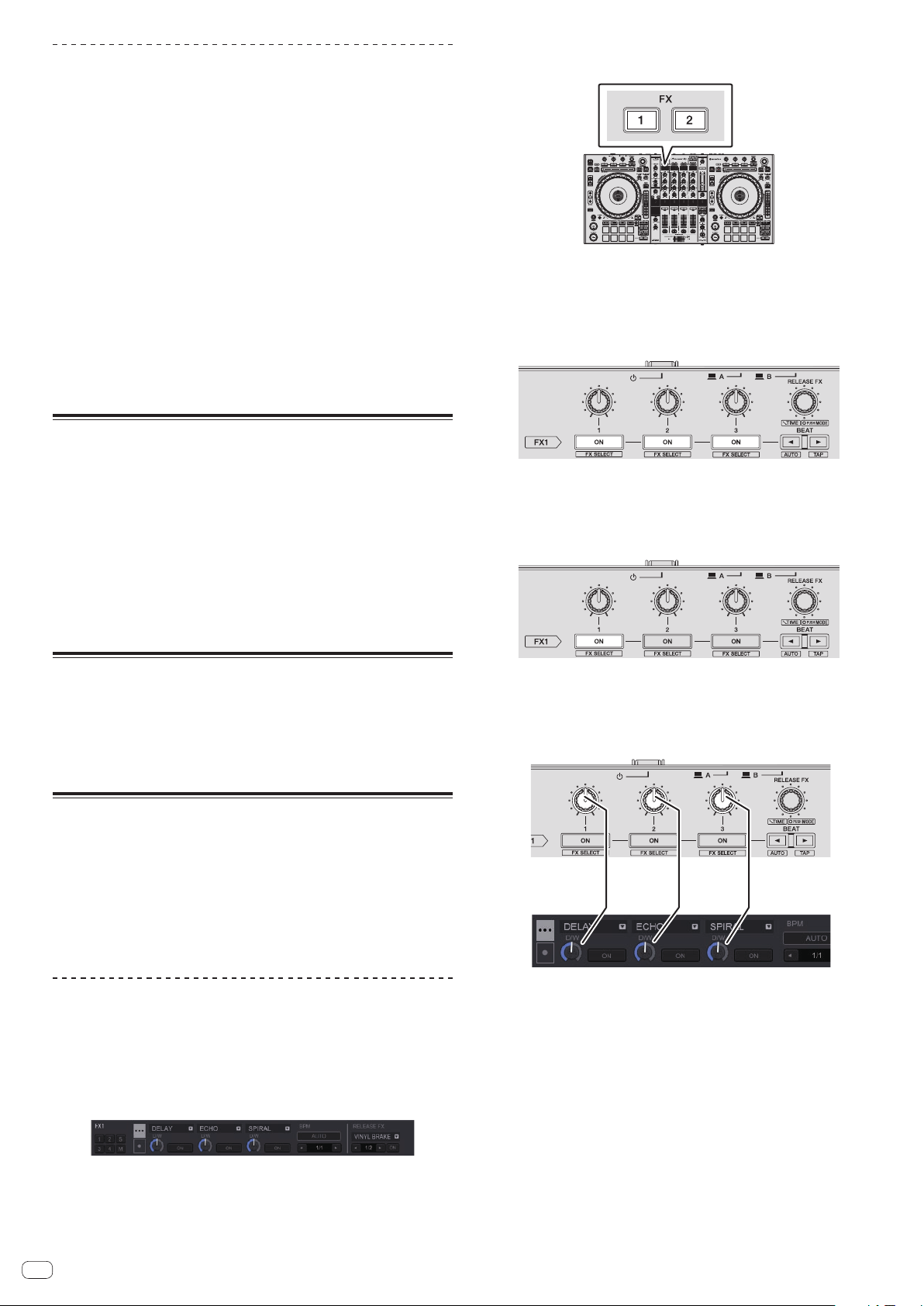
En
20
Using the crossfader start function
To use the crossfader start function, set the crossfader assign selector switch of the
channel you want to move to [A] or [B].
1 Set the cue.
Pause at the position from which you want to start playback, then press the [CUE]
button for the corresponding deck.
! Cues can also be set by moving the crossfader to the left edge or the right edge
while pressing the [SHIFT] button in the pause mode.
2 Move the crossfader to the left edge or right edge position.
Set to the edge opposite the side on which the channel you want to use with the
fader start function is set.
3 While pressing the [SHIFT] button, move the crossfader in
the opposite direction from the left edge or right edge.
Playback of the track starts from the set cue point.
! When the crossfader is returned to the original position while pressing the
[SHIFT] button during playback, the track moves instantaneously back to the set
cue point and the pause mode is set (Back Cue).
If no cue is set, playback starts from the beginning of the track.
When the crossfader is moved from the left edge to the right edge (or from the
right edge to the left edge) while pressing the [SHIFT] button when standing by
at a cue, track playback starts from the set cue point.
Adjusting the crossfader’s operating load
The load (resistance) when the crossfader is operated can be adjusted using a
flathead screwdriver.
! You can adjust the play (cut lag) on both edges of the crossfader. For details, see
Adjusting the crossfader cut lag on page 26 .
1 Move the crossfader to the right edge.
2 Insert the flathead screwdriver into the [FEELING ADJUST]
adjustment hole and turn it.
— Turn clockwise: The load decreases (the resistance of fader movement gets
weaker).
— Turn counterclockwise: The load increases (the resistance of fader move-
ment gets stronger).
Using effects
The effect functions of rekordbox dj can be roughly divided into three types: BEAT
FX, SOUND COLOR FX, and RELEASE FX.
The following explains how to operate the three effect function types, BEAT FX,
SOUND COLOR FX, and RELEASE FX.
For details on pad FX for operating these effects using the performance pads, see
Using the pad FX on page 16 .
Using the beat FX function
Beat FX can apply an effect matched to the tempo (BPM) of the track loaded in the
deck.
Beat FX has the two effect units FX1 and FX2, and the deck assigned on each of
these units can be freely set.
Also, beat FX has two FX modes: beat FX single mode and beat FX multi mode.
The beat FX single mode allows you to select one effect and use up to three param-
eters for one effect unit.
The beat FX multi mode allows you to use up to three effects for one effect unit
simultaneously.
Using effects in the beat FX multi mode
The following describes how to assign an effect unit to channel 1.
1 Press the [RELEASE FX] control while pressing the [SHIFT]
button to switch the FX mode of rekordbox dj to the beat FX
multi mode.
The mode switches between the beat FX multi mode and beat FX single mode each
time the buttons are operated.
2 Press the [FX1] button or [FX2] button of channel 1 to select
the effect unit to assign.
3 Press the effect parameter 1 button while pressing the
[SHIFT] button to select the first effect type.
To select the second effect type, press the effect parameter 2 button while pressing
the [SHIFT] button.
To select the third effect type, press the effect parameter 3 button while pressing the
[SHIFT] button.
The currently selected effect type is displayed on the rekordbox dj screen.
4 Press the effect parameter 1 button to turn the first effect
on.
Press the effect parameter 2 button to turn the second effect on.
Press the effect parameter 3 button to turn the third effect on.
The [ON] key for the corresponding effect is highlighted on the rekordbox dj screen.
5 Operate the effect parameter 1 control to adjust the
parameter of the first effect.
Operate the effect parameter 2 control to adjust the parameter of the second effect.
Operate the effect parameter 3 control to adjust the parameter of the third effect.
The balance between the original sound and effect sound can be adjusted.
6 Turn the [RELEASE FX] control while pressing the [SHIFT]
button.
Adjusts the effect time.
7 Press the [BEAT c/d] button.
The beat interval for applying the effect can be adjusted.
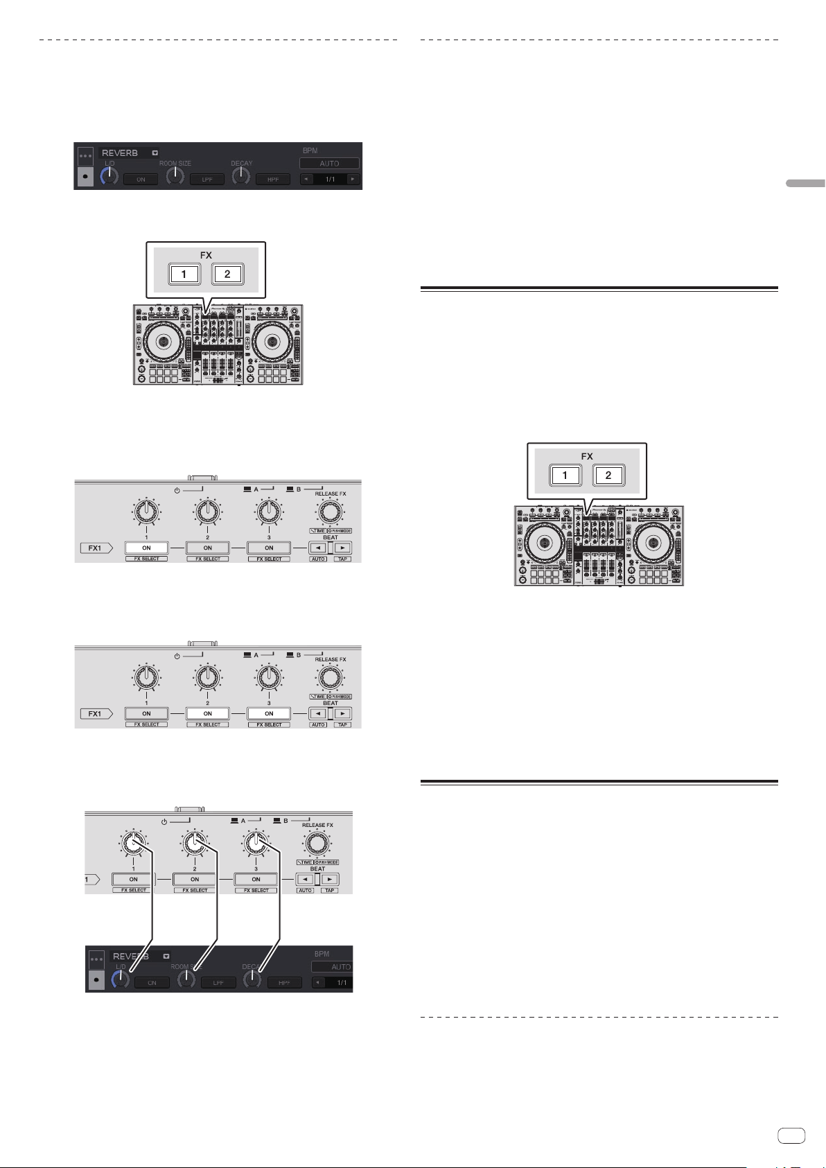
En
21
Advanced Operation
Using an effect in the beat FX single mode
The following describes how to assign an effect unit to channel 1.
1 Press the [RELEASE FX] control while pressing the [SHIFT]
button to switch the FX mode of rekordbox dj to the beat FX
single mode.
2 Press the [FX1] button or [FX2] button of channel 1 to select
the effect unit to assign.
3 Press one of the effect parameter buttons while pressing
the [SHIFT] button to select the effect type.
The selected effect is displayed on the rekordbox dj screen.
4 Press the effect parameter 1 button to turn the effect on.
The [ON] button for the effect is highlighted on the rekordbox dj screen and the
effect is enabled.
5 Operate the effect parameter 2 button or the effect
parameter 3 button to switch the effect’s parameter.
! The parameter button corresponding to the effect is highlighted on the rekord-
box dj screen, the parameter is enabled, and the effect of the effect changes.
6 Operate the effect parameter control(s) to adjust the
effect’s parameter(s).
The parameters differ depending on the effect type.
7 Turn the [RELEASE FX] control while pressing the [SHIFT]
button.
Adjusts the effect time.
8 Press the [BEAT c/d] button.
The beat interval for applying the effect can be adjusted.
Switching the effect’s tempo mode
With rekordbox dj effects, there are two ways to set the beat FX tempo: with “BPM
auto mode” and “BPM tap mode”.
! By default, the BPM auto mode is set.
BPM auto mode
The track’s BPM value is used as the basis for the effect’s tempo.
When the [BEATc] button is pressed for at least one second while pressing the
[SHIFT] button, the mode switches to the BPM auto mode.
BPM tap mode
The BPM used as the base value for the effect is calculated from the interval at
which the [BEATc] button is tapped with a finger while pressing the [SHIFT] button.
When the [BEATd] button is pressed for at least one second while pressing the
[SHIFT] button, the mode switches to the BPM tap mode.
Using the release FX
Release FX enables you to turn off the beat FX that was on up until now simultane-
ously with the adding of an effect.
The playing track and effect sound can be smoothly connected by using release FX.
One release FX per effect unit can be used in both the beat FX multi mode and beat
FX single mode.
The following describes how to assign an effect unit to channel 1.
1 Press the [FX1] button or [FX2] button of channel 1 to select
the effect unit to assign.
2 Turn the [RELEASE FX] control to select the release FX type.
The currently selected effect type is displayed on the rekordbox dj screen.
3 Click the [c] button or [d] button on the rekordbox dj
screen to set the release FX beat.
The release FX beat can be set separately from the the beat setting for beat FX.
4 Press and hold the [RELEASE FX] control.
The selected release FX turns on, and the beat FX in the same effect unit that was on
up until now turns off.
5 Release the [RELEASE FX] control.
Release FX turns off.
Using the SOUND COLOR FX function
These effects change in association with the [COLOR] controls for the different
channels.
When the unit is connected with rekordbox dj, the SOUND COLOR FX included in
rekordbox dj can be used.
SOUND COLOR FX included in the unit can be used with external input.
1 Press one of the [SOUND COLOR FX] buttons.
This selects the type of effect.
The button that was pressed flashes.
!
Even when one of the [SOUND COLOR FX] buttons is selected, if a different
[SOUND COLOR FX] button is pressed, the newly pressed button is selected.
! The same effect is set for all channels.
2 Turn the [COLOR] control.
The effect is applied to the channel(s) for which the control(s) was (were) pressed.
Canceling the SOUND COLOR FX effect
Press the flashing [SOUND COLOR FX] button.
The effect is canceled.
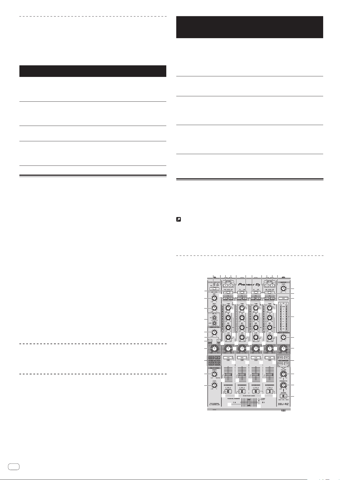
En
22
Types of SOUND COLOR FX effects
rekordbox dj includes various SOUND COLOR FX.
When the software is connected with the unit, SPACE, JET, PITCH and FILTER are
selected by default.
Effects other than these can be used by changing the SOUND COLOR FX settings in
rekordbox dj.
Switch SOUND COLOR FX of rekordbox dj to the [USER] mode to change the
SOUND COLOR FX setting. You can set each effect to the desired effect.
Effect
Name
Descriptions [COLOR] control
SPACE
Applies a reverberation effect to the
original sound.
Turn counterclockwise: Applies the
reverberation effect to the mid- and low
ranges.
Turn clockwise: Applies the reverberation
effect to the mid- and high ranges.
JET
The flanger effect is applied.
Counterclockwise: Applies a flanger
effect, which emphasizes low-pitched
sound.
Clockwise: Applies a flanger effect, which
emphasizes high-pitched sound.
PITCH
Changes the sound pitch.
Turn counterclockwise: The pitch
decreases.
Turn clockwise: The pitch increases.
FILTER
Outputs sound that has passed
through a filter.
Turn counterclockwise: Gradually
decreases the low-pass filter’s cutoff
frequency.
Turn clockwise: Gradually increases the
high-pass filter’s cutoff frequency.
Using the oscillator function
A built-in sound source can be added to the audio master output.
When the unit is connected with rekordbox dj, the sound sources of rekordbox dj
and the sound sources included in the unit can be used.
The sound sources included in the unit can be used with external input.
1 Use the [SOURCE] switch to select the channel to which you
want to add oscillator sound.
! [USB-A]: Uses the sound sources of rekordbox dj installed on the PC connected
to USB-A.
! [INT.]: Uses the sound sources of the controller unit.
! [USB-B]: Uses the sound sources of rekordbox dj installed on the PC connected
to USB-B.
2 Turn the [OSC SAMPLER PARAMETER] control.
Turning the control clockwise or counterclockwise adjusts the oscillator sound tone.
3 Turn the [OSC SAMPLER VOLUME] control.
Adjusts the sound level of oscillator sound.
4 Press one of the [OSC SAMPLER SELECT] buttons.
This selects the type of oscillator sound.
The button that was pressed flashes for a certain period of time.
! You can select more than one oscillator sound.
! The sound generating method differs depending on the [SOURCE] switch.
! [INT.]: Sound continues to be output while the button is pressed.
! [USB-A]/[USB-B]: In the [Gate Mode] setting of the connected rekordbox, you
can switch between outputting sound while the button is pressed and playing
back to the end of the track if the button is pressed.
For details, see the rekordbox software’s manual.
Quitting the oscillator function
Oscillator sound automatically stops after a certain period of time and the
[OSC SAMPLER SELECT] button changes from flashing to lighted.
Type of oscillator sound
When the software is connected with the unit, the following sound sources are
selected by default.
The oscillator of rekordbox dj can be changed to the desired sound source.
For how to change the sound source of the oscillator, see the rekordbox soft-
ware’s manual.
Effect Name Descriptions
OSC SAMPLER PARAMETER
control (when using sound
sources included in the
unit)
NOISE
Generates white noise.
Turn counterclockwise: The cut-
off frequency of the filter through
which the white noise passes
gradually decreases.
Turn clockwise: The cut-off fre-
quency of the filter through which
the white noise passes gradually
increases.
SINE
Generates sine wave sound.
Turn counterclockwise: Reduces
the frequency of the sine wave.
Turn clockwise: Increases the
frequency of the sine wave.
SIREN
Generates a siren-like sound.
Turn counterclockwise: Reduces
the reverberation time of the siren
sound.
Turn clockwise: Increases the
reverberation time of the siren
sound.
HORN
Generates a horn-like sound.
Turn counterclockwise: Reduces
the reverberation time of the horn
sound.
Turn clockwise: Increases the
reverberation time of the horn
sound.
! When using the sound sources included in rekordbox dj, you can control the
sound pitch with the OSC SAMPLER PARAMETER control. Left turn lowers the
pitch, and right turn raises the pitch.
Using external inputs
This unit is equipped with four sets of external inputs for connecting CD players,
analog turntables, etc. This unit’s 4-channel mixer can be used to mix externally
input sound without passing through a computer. The mixer functions below can be
used without a computer connected.
Notes
! For details on the respective items, see Connections (p. 6 ) and Part names and
functions (p. 8 ).
! The functions of rekordbox dj do not work for external input.
! The values adjusted with the various controls for rekordbox dj differ from the
values adjusted with the various controls for external input.
Mixer section
1 2 2 2 23 4 3 4
6
9
5
7
8
a
b
c
d
e
f
g
h
j
k
l
m
o
t t t t
i
x x x x
v
w w w w
v v v
y y
z
q
s s s s
n
r
q
r
q
r
q
r
p
p
o
u u u u
yy
A
1 OFF, ON, TALK OVER selector switch
2 USB connection indicator
3 USB (A) button
4 USB (B) button
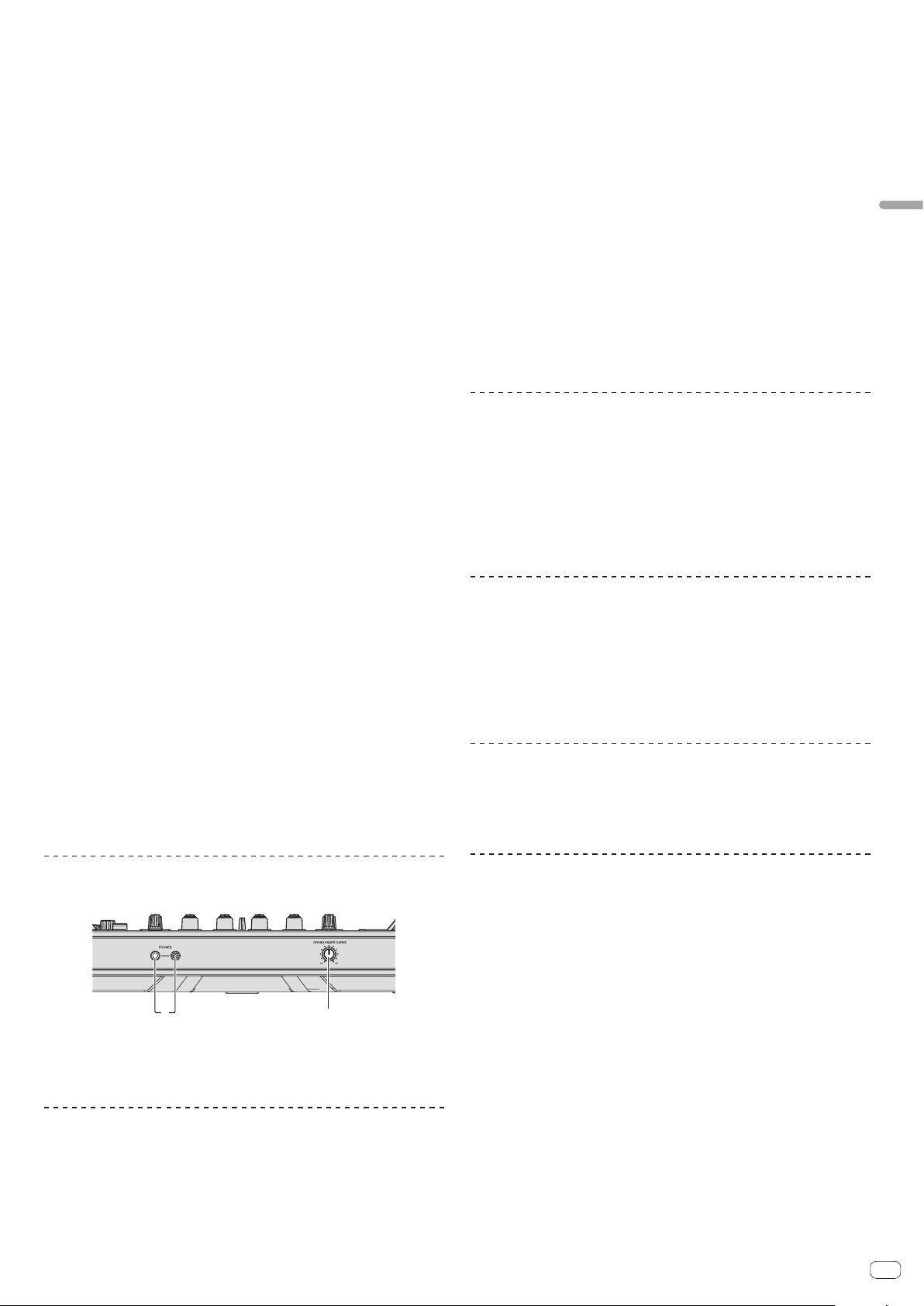
En
23
Advanced Operation
5 MASTER LEVEL control
6 MASTER CUE button
7 Master level indicator
8 BOOTH MONITOR control
9 MASTER OUT COLOR control
a OSC SAMPLER SELECT button
b OSC SAMPLER VOLUME control
c OSC SAMPLER PARAMETER control
d SOURCE selector switch
e HEADPHONES LEVEL control
f HEADPHONES MIXING control
g SOUND COLOR FX buttons
h MIC COLOR control
i SAMPLER SYNC button
j SAMPLER CUE button
k SAMPLER VOLUME control
l EQ (HI, LOW) controls
m MIC2 control
n MIC1 control
o CD, USB selector switch
p LINE, PHONO, USB selector switch
q FX 1 assign button
r FX 2 assign button
s Channel Level Indicator
t TRIM control
u ISO (HI, MID, LOW) controls
v COLOR control
w Headphones CUE button
x Channel fader
y Crossfader assign selector switch
z Crossfader
A FEELING ADJUST adjustment hole
Front panel
12
1 PHONES jacks
2 CROSS FADER CURVE selector switch
Using a microphone
1 Connect a microphone to the [MIC1] or [MIC2] terminal.
2 Set the [OFF, ON, TALK OVER] selector switch to [ON] or
[TALK OVER].
— [ON]: The indicator lights.
— [TALK OVER]: The indicator flashes.
! When set to [TALK OVER], the sound of channels other than the [MIC1] channel
is attenuated by 18 dB (default) when a sound of –10 dB or greater is input to the
microphone.
! The sound attenuation level while [TALK OVER] is selected can be changed in
utility mode. For the method to effect that change, see Changing the talk over
function level on page 26 .
! The talk over mode can be switched to the normal mode or the advanced mode.
For instructions on changing it, see Changing the talk over function setting on
page 25 .
3 Turn the [MIC1] or [MIC2] control.
Adjust the level of the sound output from the [MIC1] channel.
! Pay attention that rotating to the extreme right position outputs a very loud
sound.
4 Input audio signals to the microphone.
Adjusting the sound quality
Turn the [EQ (HI, LOW)] controls.
The adjustable ranges for the respective controls are as shown below.
! HI: –12 dB to +12 dB (10 kHz)
! LOW: –12 dB to +12 dB (100 Hz)
Mixing the sound of a DJ player, etc.
1 Connect the DJ player or other line level output device to
the [CD] or [LINE] terminals.
2 Set the [LINE, PHONO, USB] selector switch or [CD, USB]
selector switch to [LINE] or [CD].
3 Operate the [TRIM] control and channel fader to adjust the
sound level output from each channel.
Mixing the sound of an analog turntable, etc.
1 Connect the analog player or other phono level (for MM
cartridges) output device to the [PHONO] terminals.
2 Set the [LINE, PHONO, USB] selector switch to [PHONO].
3 Operate the [TRIM] control and the channel faders to adjust
the audio level output from the respective decks.
Using SOUND COLOR FX with external input
The four SOUND COLOR FX types included in the unit can be used with external
input.
For how to operate SOUND COLOR FX, see Using the SOUND COLOR FX function on
page 21 .
Using the oscillator function with external input
The four oscillator types included in the unit can be used with external input.
For how to operate the oscillator, see Using the oscillator function on page 22 .
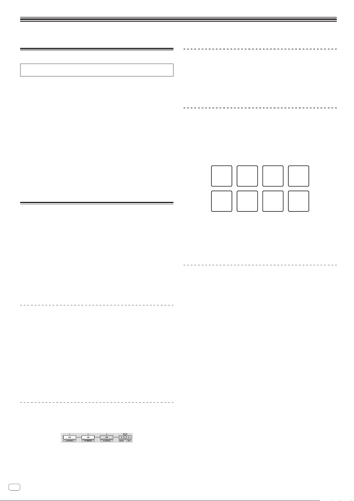
En
24
Changing the settings
Launching utilities mode
If the utilities mode is launched while the DJ application is running, the set status
may not be displayed properly.
1 Disconnect the USB cable from your computer.
2 Press the [u] switch on this unit’s rear panel to set this
unit’s power to standby.
Set this unit’s power to the standby mode.
3 While pressing both the [SHIFT] and [PLAY/PAUSE f]
buttons on the left deck, press the [u] switch on this
unit’s rear panel.
Utilities mode is launched.
4 After setting this unit to the utility settings mode, operate
the controller for the item whose settings you want to
change.
See the explanations below for the settings that can be changed.
5 Press the [u] switch on this unit’s rear panel to set this
unit’s power to standby.
To save the settings, set the [u] switch on this unit’s rear panel to standby and quit
utilities mode.
Utilities modes
The following settings can be changed:
! MIDI controller setting
! Fader start setting
! Master output attenuator level setting
! Slip mode flashing setting
! Demo mode setting
! Setting of the velocity curve in the sampler velocity mode
! Setting for sending intervals of the jog dial’s MIDI message
! Setting of the auto standby function
! Setting of talk over function
! Setting of talk over function level
! Cut lag setting of crossfader
! Output setting of microphone to booth monitor
! Peak limiter setting
! Brightness setting of jog ring
Forcefully using the unit as the general MIDI
controller
The unit automatically changes operation as follows depending on whether rekord-
box is running.
! When rekordbox is running, controller operation depends on the rekordbox
functions.
! When rekordbox is not running, the unit operates as a general MIDI controller.
Even though rekordbox is running, you can forcefully operate the unit as a general
MIDI controller.
Press the [MASTER TEMPO] button on the left deck.
! [MASTER TEMPO] button off: Operation automatically changes depending on
whether or not rekordbox is running.
! [MASTER TEMPO] button lit: Regardless of whether or not rekordbox is running,
the unit is forcefully operated as a general MIDI controller.
Changing the fader start setting
The fader start function’s setting can be changed.
Press one of the effect parameter buttons on the left deck.
! Effect parameter 1 button lit: Fader start enabled
! Effect parameter 2 button lit: Fader start disabled
Setting the master output’s attenuator level
! The default is 0 dB.
Press one of the left deck’s [HOT CUE] mode, [PAD FX1] mode,
and [SLICER] mode buttons.
! [HOT CUE] mode button lit: 0 dB (no attenuation)
! [PAD FX1] mode button lit: –3 dB
! [SLICER] mode button lit: –6 dB
Changing the slip mode flashing setting
When slip mode is on, the buttons available in slip mode (such as the jog dial indi-
cator, [AUTO BEAT LOOP] button, and [PLAY/PAUSE f] button) can be set to
flash or not flash. The flashing method of the [SLIP] button in slip mode also varies
depending on the setting.
! By default, slip mode flashing is set to mode 1.
Press the performance pad on the left side to select a setting.
The currently selected setting can be understood by looking at which pad lights.
Mode 1 Mode 2 Off
! Mode 1: When slip mode is turned on, the buttons available in slip mode flash
for approximately one second. During slip mode, the [SLIP] button flashes only
while payback continues in the background.
! Mode 2: When the slip mode is turned on, the buttons available in slip mode
flash for approximately one second. During slip mode, the [SLIP] button contin-
ues flashing.
! Off: The buttons available in slip mode do not flash. During slip mode, the [SLIP]
button flashes only while payback continues in the background.
Changing the demo mode setting
On this unit, the demo mode is set if no operation is performed for 10 minutes under
normal usage conditions. This demo mode can be changed.
! By default, demo mode starts when there is no operation for 10 minutes.
! When any control or button on this unit is operated while in the demo mode, the
demo mode is canceled.
Press one of the [SOUND COLOR FX] buttons.
! [SPACE] button lit: Demo mode is disabled
! [JET] button lights: Demo mode starts when there is no operation for 1 minute
! [PITCH] button lights: Demo mode starts when there is no operation for 5
minutes
! [FILTER] button lights: Demo mode starts when there is no operation for 10
minutes
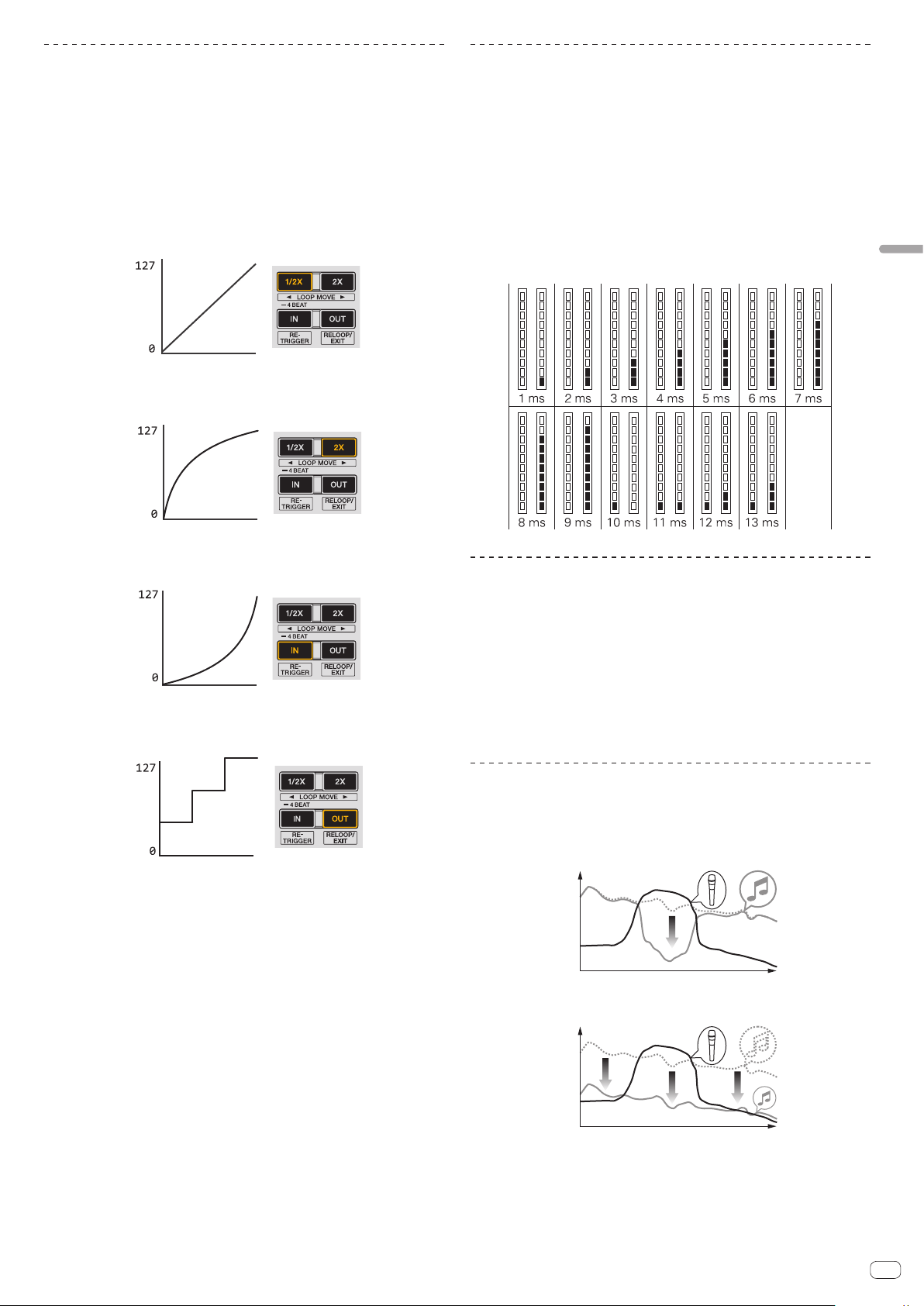
En
25
Changing the settings
Changing the velocity curve setting of velocity
sampler mode
Set the velocity curve of the velocity sampler mode. The velocity curve can be
selected from four types.
! By default, curve 3 is set.
Press the [AUTO BEAT LOOP] button on the deck whose
setting you want to set.
The velocity curve setting changes each time the [AUTO BEAT LOOP] button is
pressed.
The currently set value is indicated by how the [LOOP 1/2X], [LOOP 2X], [LOOP IN]
and [LOOP OUT] buttons light.
Curve 1
MIDI
code
Strength which
performance pad is pressed
Min. Max.
Curve 2
MIDI
code
Strength which
performance pad is pressed
Min. Max.
Curve 3
MIDI
code
Strength which
performance pad is pressed
Min. Max.
Curve 4
MIDI
code
Strength which
performance pad is pressed
Min. Max.
Adjusting the jog dial’s MIDI message sending
interval
This unit is equipped with a mode for adjusting the jog dial’s MIDI message sending
interval.
Depending on your computer’s operating system and specifications, the jog dial
may not operate properly if the sending interval of MIDI message for JOG dial is too
short. In this case, follow the procedure below to adjust the MIDI message sending
interval.
! From a short MIDI sending interval, increase the interval to a length at which no
problems occur.
! The default is 1 ms.
Press the [SHIFT] button on the left deck.
The MIDI message sending interval setting changes each time the button is
pressed. The currently set value is indicated by how the master level indicator is lit.
Disabling the auto standby function
! When auto standby function is set to on, if 4 hours have passed while the follow-
ing conditions are all met, the unit automatically enters standby status.
— Buttons and controls of the unit except the [MIC1] control and [MIC2] control
are not operated.
— That no audio signals of -18 dB or greater are input to this unit’s input terminals.
! When the [PANEL (WAKE UP)] button is pressed, the standby mode is canceled.
! By default, the auto standby function is enabled.
Press the [GRID ADJUST] button of the left side deck.
! [GRID ADJUST] button lit: Auto standby function is enabled
! [GRID ADJUST] button off: Auto standby function is disabled
Changing the talk over function setting
About talk over mode
The talk over function has the two modes described below.
Advanced talk over mode: Sound other than the microphone channel is output with
only the midrange attenuated per the talk over level setting.
dB
Frequency
Normal talk over mode: Sound other than the microphone channel is output attenu-
ated per the talk over level setting.
dB
Frequency
! By default, the advanced talk over mode is set.
Press the [GRID SLIDE] button of the left side deck.
! [GRID SLIDE] button lit: Advanced talk over mode
! [GRID SLIDE] button off: Normal talk over mode
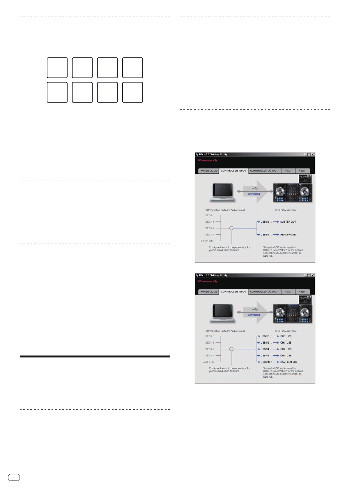
En
26
Changing the talk over function level
Sets the talk over function’s sound attenuation level.
! By default, the level is set to -18 dB.
Press the performance pad on the left side to select a setting.
The currently selected setting can be understood by looking at which pad lights.
–6 dB –12 dB –18 dB –24 dB
Adjusting the crossfader cut lag
Adjust the play (cut lag) on both edges of the crossfader. It can be adjusted between
0 (0.74 mm) and 52 (5.94 mm) in units of 0.1 mm.
! By default, it is set to 6 (1.34 mm).
Turn the rotary selector on the left deck.
The current setting (0 to 52) is displayed by the lit condition of the channel level
indicator.
! Number of lit segments of the [CH3] channel level indicator: Ten’s place
! Number of lit segments of the [CH1] channel level indicator: One’s place
Setting the microphone output of the booth
monitor
! By default, it is set to output microphone sound from the [BOOTH OUT]
terminal.
Press the [SLIP] button of the left deck.
! [SLIP] button lit: Outputs microphone sound from the [BOOTH OUT] terminal
! [SLIP] button off: Does not output microphone sound from the [BOOTH OUT]
terminal
Changing the peak limiter setting
Lessens sudden, unpleasant digital clipping of the master output.
! By default, the peak limiter is set to enabled.
Press the [LOAD] button of the left side deck.
! [LOAD] button lit: Peak limiter enabled
! [LOAD] button off: Peak limiter disabled
Adjusting the brightness of jog ring
You can adjust the brightness of the illumination around the jog dial.
!
The same setting is applied to the jog dials on the left and right decks.
! By default, it is set to bright light.
Press the top of the jog dial.
Each time the top of the jog dial is pressed, the setting changes.
The brightness can be set in three levels: light, dark, and off. The current setting can
be understood by the jog ring lit condition.
About the setting utility software
The setting utility can be used to make the checks and settings described below.
— Setting the Mixer Mode
— Checking the status of this unit’s input selector switches
— Setting the audio data output from this unit to the computer
— Adjusting the buffer size (when ASIO is used)
— Checking the version of the driver software
Displaying the setting utility
For Windows
Click [Start] menu > [All Programs] > [Pioneer] > [DDJ-RZ] > [DDJ-RZ Settings
Utility].
For Mac OS X
Click [Macintosh HD] icon > [Application] > [Pioneer] > [DDJ-RZ] > [DDJ-RZ
Settings Utility].
Setting the Mixer Mode
Display the setting utility before starting.
1 Click the [Mixer Mode] tab.
2 Click the pull-down menu.
Select Mixer Mode according to the operating environment.
Internal Mixer Mode
! Select this when using the DJ application internal mixer.
External Mixer Mode
! Select this when inputting the audio output of each deck of the DJ applica-
tion to each channel of DDJ-RZ.
! rekordbox dj operates as Internal Mixer Mode regardless of the Mixer Mode
setting.
!
When using rekordbox dj, set this to Internal Mixer Mode.
Checking the status of this unit’s input selector
switches
Display the setting utility before starting.
Click the [CONTROLLER INPUT] tab.
When Mixer Mode is Internal Mixer Mode
When Mixer Mode is External Mixer Mode
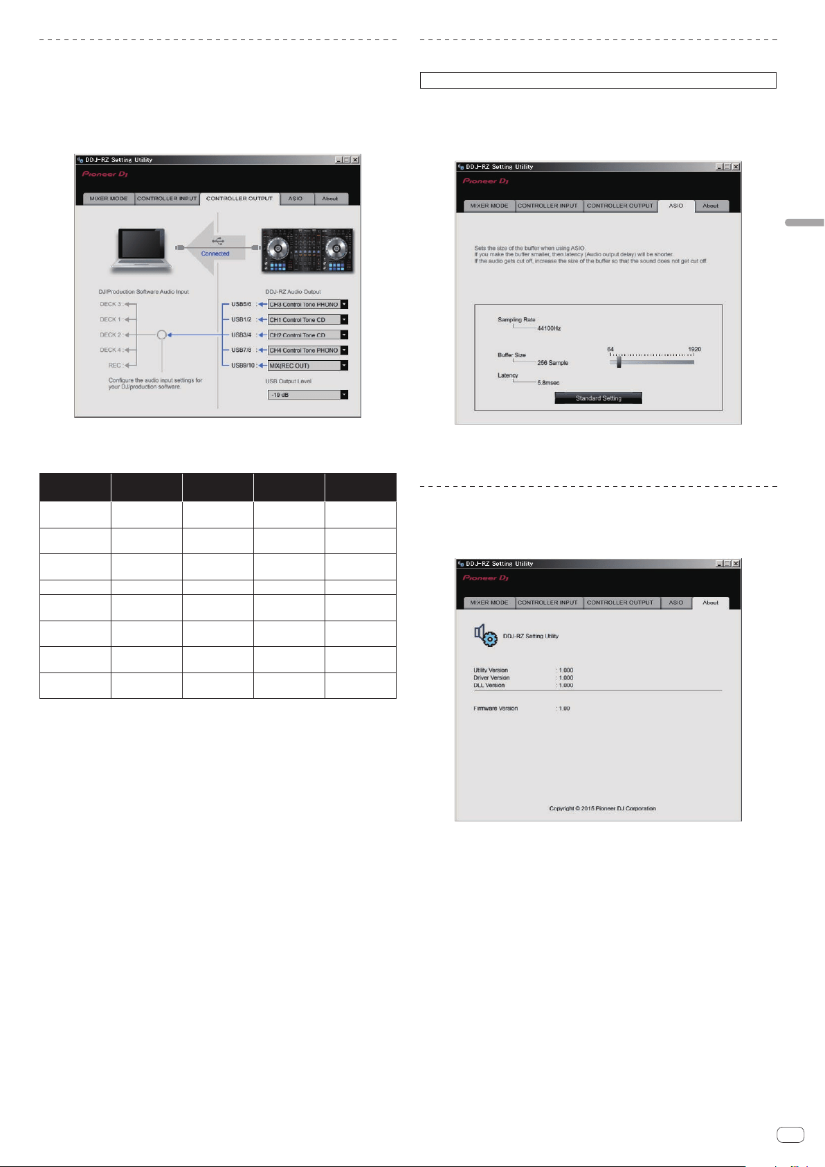
En
27
Changing the settings
Setting the audio data output from this unit to
the computer
When rekordbox is running and using this unit as the default audio device, set the
audio data output in rekordbox.
Display the setting utility before starting.
1 Click the [CONTROLLER OUPUT] tab.
2 Click the [DDJ-RZ Audio Output] pull-down menu.
Select and set the audio data to be output to the computer from the flow of audio
signals inside this unit.
CH1 (USB1/2) CH2 (USB3/4) CH3 (USB5/6) CH4 (USB7/8)
CH5
(USB9/10)
— —
CH3 Control
Tone PHONO
1
CH4 Control
Tone PHONO
1
MIX (REC
OUT)
2
CH1 Control
Tone CD
1
CH2 Control
Tone CD
1
CH3 Control
Tone LINE
1
CH4 Control
Tone LINE
1
Cross Fader A
2
Post CH1
Fader
2
Post CH2
Fader
2
Post CH3
Fader
2
Post CH4
Fader
2
Cross Fader B
2
Cross Fader A
2
Cross Fader A
2
Cross Fader A
2
Cross Fader A
2
MIC
Cross Fader B
2
Cross Fader B
2
Cross Fader B
2
Cross Fader B
2
Post CH1
Fader
2
MIC MIC MIC MIC
Post CH2
Fader
2
— — — —
Post CH3
Fader
2
— — — —
Post CH4
Fader
2
1 The audio data is output with the same volume at which it is input to this unit, regardless of
the [USB Output Level] setting.
2 When using for applications other than recording, pay attention to the DJ application’s set-
tings so that no audio loops are generated. If audio loops are generated, sound may be input
or output at unintended volumes.
! When there is a connection with rekordbox dj, the CH5 setting cannot be changed to other
than [MIX (REC OUT)].
3 Click the [USB Output Level] pull-down menu.
Adjust the volume of the audio data output from this unit.
! The [USB Output Level] setting is applied equally to all audio data. However,
when 1 on the table at step 2 is selected, the audio data is output with the same
volume at which it is input to this unit.
! If not enough volume can be achieved with the DJ software’s volume adjustment
alone, change the [USB Output Level] setting to adjust the volume of the audio
data output from this unit. Note that the sound will be distorted if the volume is
raised too high.
Adjusting the buffer size (when ASIO is used)
This function can only be used by those using a Windows operating system.
If an application using this unit as the default audio device (DJ software, etc.) is run-
ning, quit that application before adjusting the buffer size.
Display the setting utility before starting.
Click the [ASIO] tab.
! If the buffer size is made large, drops in audio data (breaks in the sound) occur
less easily, but the time lag due to the delay in the transfer of the audio data
(latency) increases.
Checking the version of the driver software
Display the setting utility before starting.
Click the [About] tab.
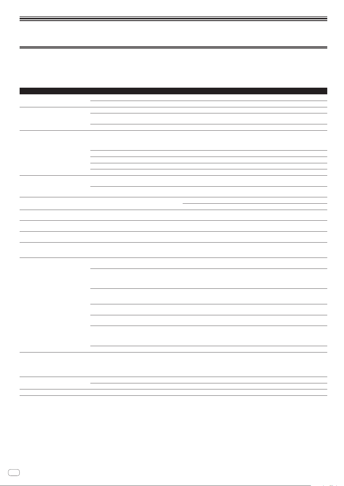
En
28
Additional information
Troubleshooting
! If you think that there is something wrong with this unit, check the items below and access the Pioneer DJ site and check [FAQ] for the [DDJ-RZ].
Sometimes the problem may lie in another component. Inspect the other components and electrical appliances being used. If the problem cannot be rectified, ask your
nearest Pioneer authorized service center or your dealer to carry out repair work.
! This unit may not operate properly due to static electricity or other external influences. In this case, proper operation may be restored by turning the power off, waiting 1
minute, then turning the power back on.
Problem Check Remedy
The power is not turned on.
Is the [u] switch of the power on? Turn the [u] switch of the power on.
Is the power cord properly connected?
Plug in the power cord to an AC outlet. (page 6 )
This unit is not recognized. Is the included USB cable properly connected? Connect the included USB cable properly.
Are you using a USB hub? USB hubs cannot be used. Connect the computer and this unit directly using the included
USB cable.
Is the driver software properly set?
Set the driver software properly. (page 4 )
No sound or small sound. Are the [TRIM] control, channel fader, crossfader, the
[LINE, PHONO, USB] selector switch (or the [CD, USB]
selector switch) and the [MASTER LEVEL] control set to
the correct position?
Set the [TRIM] control, channel fader, crossfader, the [LINE, PHONO, USB] selector switch
(or the [CD, USB] selector switch) and the [MASTER LEVEL] control to the correct position.
Are the connected powered speakers, etc., properly set? Properly set the external input selection, volume, etc., on the powered speakers, etc.
Are the connection cables properly connected? Connect the connection cables properly.
Are the terminals and plugs dirty? Clean the terminals and plugs before making connections.
Is the driver software properly set?
Set the driver software properly. (page 4 )
Distorted sound. Is the [MASTER LEVEL] control set to the proper position? Adjust the [MASTER LEVEL] control so that the master level indicator’s orange indicator
lights at the peak level.
Is the [TRIM] control set to the proper position? Adjust the [TRIM] control so that the channel level indicator’s orange indicator lights at the
peak level.
Sound being played is interrupted when
using DJ software.
Is the driver software’s latency value suitable? Set the driver software’s latency to a suitable value.
Set the DJ software’s latency to a suitable value.
Cannot output the microphone sound. Are the [OFF, ON, TALK OVER] selector switches set to
the proper position?
Set the [OFF, ON, TALK OVER] selector switches to the proper position.
Cannot output the sound of the external
device.
Is the [LINE, PHONO, USB] selector switch (or [CD, USB]
selector switch) set to the proper position?
Set the [LINE, PHONO, USB] selector switch (or [CD, USB] selector switch) to the proper
position.
Sound is interrupted when the ASIO driver
is set.
Has the ASIO driver been set with rekordbox running?
Set the ASIO driver before launching rekordbox. (page 27 )
The indicator flashes and operation is
strange.
— Normal operation can sometimes be restored by unplugging the power cord, waiting at least
1 minute, then plugging the power cord back in. If the symptom persists, unplug the power
cord and request repairs.
Operation of rekordbox dj becomes
unstable.
Are you using the latest version of the software? Free updates of rekordbox can be downloaded from the website. Use the most recent version.
(page 4 )
Are you using softwares other than rekordbox at the same
time?
Quit other applications to decrease the load on the computer.
If operation continues to be unstable, try disabling the wireless network or other wireless
connections, antivirus software, the screen saver, the low power mode, etc.
(page 4 )
When other USB devices are connected to the computer. Disconnect other USB devices from the computer.
When another USB audio device is connected to the computer at the same time, it may not
operate or be recognized normally.
Are you using a USB hub? USB hubs cannot be used. Connect the computer and this unit directly using the included
USB cable.
There is a problem with the USB port to which this unit is
connected.
If your computer has multiple USB ports, try connecting this unit to a different USB port.
Is this unit connected to a notebook computer running on
its battery?
Supply power to the notebook computer from an AC power supply.
(Depending on the notebook computer’s settings, the low power mode may be set when the
computer is running on its battery, automatically reducing the performance of the computer
itself.) (page 4 )
The USB buffer size is too small. Raise the USB buffer size. (page 27 )
The jog dial illumination does not turn dur-
ing playback. (It does turn when scratching.)
The [TEMPO] slider does not work when the
deck is switched while the sync mode is set.
(The TAKEOVER indicator lights.)
Is the setting in the utilities mode wrong? In utilities mode, check that the unit is not set to be forcefully operated as a general MIDI
controller.
The fader start function does not work. Is a cue set?
Set a cue. (page 19 )
Is the setting in the utilities mode wrong? Enable the fader start setting in the utilities mode.
The USB connection indicator flashes. Is the driver software properly set?
Set the driver software properly. (page 4 )
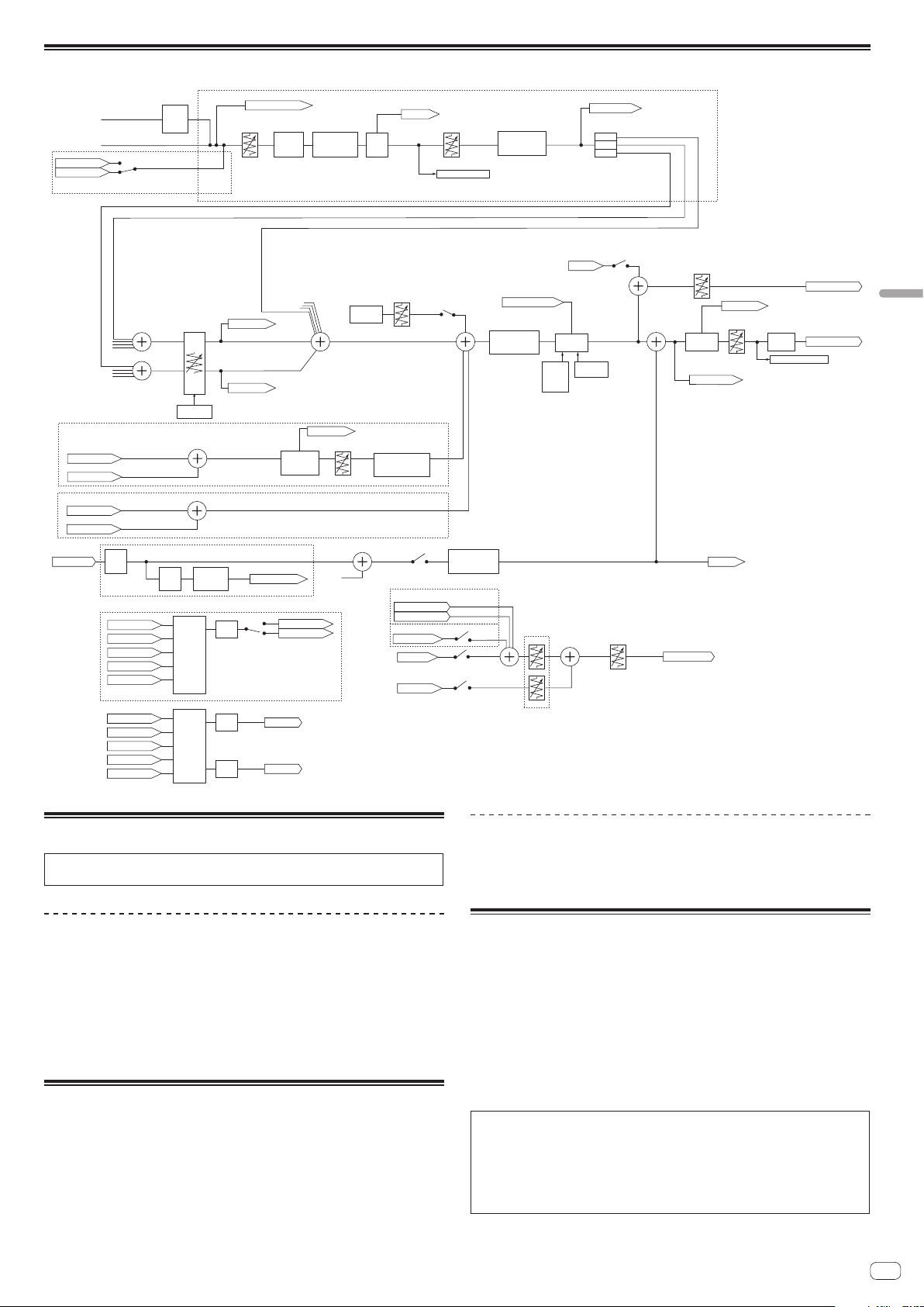
En
29
Additional information
Signal flow
Peak
Limiter
External Mixer Mode only
SAMPLER Cue
Internal Mixer Mode only
CHx Cue
Headphone Mix
Headphone Level
Master Cue
Headphone Out
SOUND
COLOR EFFECT
CHx
SOUND
COLOR EFFECT
CHx
3Band
ISOLATOR
CHx
Level Meter CHx
CUE
Monitor
CHx
Phono
AMP
CH3,4
Analog PHONO
Analog CD/LINE
CF Assign
Assign A
CHx
Assign THRU
CH1-4
Assign B
CHx
CH Fader
Cross Fader
Curve
Thru
CF A
CF B
CHx Control Tone
2Band
MIC EQ
MIC1/2
MIC1/2 in
Post CHx Fader
TalkOver ON/OFF
MIX (Rec Out)
Master Cue
MIC
MIC
Cross Fader B
Cross Fader A
SAMPLER Cue
Level meter Master
CH1-4 Common
MIC1,2 Common
External Mixer Mode only
Digital Trim
CHx Cue
Cross Fader
Sampler
Volume
Talk Over
Oscillator
Master
Cue
Talk Over
Level
Talk Over
Mode
Advanced
/Normal
SOUND
COLOR EFFECT
Master
Master
Level
Booth Level
MIC to
Booth Monitor On/Off
Oscillator
Source Select
OSC Level
Booth Out
Master Out
MIC
Filter
MIC In
Level Detect
TalkOver ON/OFF
MIC 1,2 MIX
USB A CHx in
USB B CHx in
External Mixer Mode only
SOUND
COLOR EFFECT
MIC
CH1-4 Common
USB A MONITOR
CHx Control Tone
Post CHx Fader
Cross Fader A
Cross Fader B
MIC
USB B MONITOR
Boost
Output
Select
USB A Rec
Post CHx Fader
Cross Fader A
Cross Fader B
MIC
MIX(REC OUT)
Boost
USB B Rec
Boost
Output
Select
USB A SAMPLER
USB B SAMPLER
Internal Mixer Mode only
USB A MASTER
USB B MASTER
CUE
Monitor
Sampler
SOUND
COLOR EFFECT
Sampler
USB A CHx out
USB B CHx out
Acquiring the manual
Various instructions are sometimes provided as files in PDF format.
Adobe
®
Reader
®
must be installed in order to view PDF format files.
Downloading the rekordbox software manual
1 Launch a web browser on the computer and access the
rekordbox site below.
http://rekordbox.com/
2 Download the software manual from the rekordbox
software manual download page.
For inquiries on rekordbox, see the rekordbox site indicated above.
Using as a controller for other DJ
software
This unit also outputs the operating data for the buttons and controls in MIDI for-
mat. If you connect a computer with a built-in MIDI-compatible DJ software via a
USB cable, you can operate the DJ software on this unit. The sound of music files
being played on the computer can also be output from the DDJ-RZ.
To use as a controller to operate DJ software other than rekordbox, switch to the
setting for using software other than rekordbox in the utilities mode. Also, set the DJ
software’s audio and MIDI related settings.
! For details, see your DJ software’s operating instructions.
About MIDI messages
For details on this unit’s MIDI messages, see “List of MIDI Messages”.
! “List of MIDI Messages” can be acquired from the following URL:
http://www.pioneerdj.com/
About trademarks and registered
trademarks
! "Pioneer DJ" is a trademark of PIONEER CORPORATION, and is used under
license.
rekordbox is a trademark or registered trademark of the Pioneer DJ Corporation.
! Microsoft and Windows are either registered trademarks or trademarks of
Microsoft Corporation in the United States and/or other countries.
! Mac OS, iTunes, and Finder are trademarks of Apple Inc., registered in the U.S.
and other countries.
! ASIO is a trademark of Steinberg Media Technologies GmbH.
The names of companies and products mentioned herein are trademarks or regis-
tered trademarks of their respective owners.
This product has been licensed for nonprofit use. This product has not been
licensed for commercial purposes (for profit-making use), such as broadcast-
ing (terrestrial, satellite, cable or other types of broadcasting), streaming on the
Internet, Intranet (a corporate network) or other types of networks or distributing
of electronic information (online digital music distribution service). You need to
acquire the corresponding licenses for such uses. For details, see http://www.
mp3licensing.com.

En
30
Cautions on copyrights
rekordbox restricts playback and duplication of copyright-protected music contents.
! When coded data, etc., for protecting the copyright is embedded in the music
contents, it may not be possible to operate the program normally.
! When rekordbox detects that coded data, etc., for protecting the copyright is
embedded in the music contents, processing (playback, reading, etc.) may stop.
Recordings you have made are for your personal enjoyment and according to copy-
right laws may not be used without the consent of the copyright holder.
! Music recorded from CDs, etc., is protected by the copyright laws of individual
countries and by international treaties. It is the full responsibility of the person
who has recorded the music to ensure that it is used legally.
! When handling music downloaded from the Internet, etc., it is the full respon-
sibility of the person who has downloaded the music to ensure that it is used in
accordance with the contract concluded with the download site.
— The specifications and design of this product are subject to change without
notice.
© 2015 Pioneer DJ Corporation. All rights reserved.
<DRI1319-A>