Loading ...
Loading ...
Loading ...
EN
140
Installation
www.bora.com
1
2
2
3
1
4
5
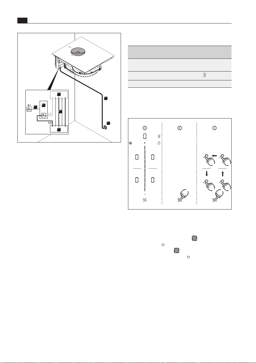
Fig. 10.42 Connection diagram with external switch
contact
[1] Cooktop and cooktop extractor power supply
cable
[2] Power supply
[3] Cooktop and cooktop extractor power supply
[4] Switch relay
[5] Switch connection S1 and switch relay
[S1] External switch contact
10.9 Initial operation
i
During initial operation some basic settings
(basic configuration) must be applied using
the dealer and service menu.
10.9.1 Dealer and service menu
i
The dealer and service menu can be called up
up to 2 minutes after the appliance has been
connected to the power supply.
i
The system adopts and saves the settings
made when you exit the corresponding menu
item.
i
Below you will find explanations on how to
use the menu and a description of the most
important menu items.
Dealer and service menu overview
Menu item/Description/Selection
area
Factory
setting
B Extraction system (exhaust air/
recirculation system)
Recirculation
C Power management
D Demo mode Off
Tab. 10.3 Menu overview
Calling up the dealer and service menu
X Connect the appliance to the power supply.
1
23
4
Fig. 10.43 Calling up the dealer and service menu
O
The standard display appears and the fan symbol
pulses for 2 minutes.
X Long press on the fan button .
O
4 input points are shown.
X Keep the fan button pressed and at the same
time press the input points in the specified
order.
O
Menu item B is displayed.
Loading ...
Loading ...
Loading ...