Loading ...
Loading ...
Loading ...
20
ALIGNMENTS AND ADJUSTMENT, Continued
IF THE OVEN BURNER DOES NOT IGNITE WITHIN 20 TO 60
SECONDS AFTER THE PILOT IS LIGHTED, TURN THE OVEN
TEMPERATURE CONTROL TO OFF AND WAIT FOR POWER TO BE
RESTORED. DO NOT ATTEMPT TO RELIGHT THE PILOT AGAIN.
If the oven does not function properly when the power is restored, or at any other time, call
a serviceman to determine the source of the problem. DO NOT ATTEMPT TO SERVICE
THE RANGE YOURSELF.
NEVER LEAVE THE CONTROL KNOBS IN ANY POSITION OTHER THAN
“OFF” IF THE IGNITORS OR BURNERS AREN’T WORKING PROPERLY.
7. Automatic Oven Safety Valve
The orice hood on the oven safety valve regulates the ow of gas to the oven burner.
This valve adjusts in the same manner as the top burner valves and is located at the base
of the oven burner in the broiler compartment of the range. To gain access, simply
remove the broiler section. When set for LP, the orice hood is screwed snugly on the
valve. To adjust for use on Natural Gas, unscrew the orice hood until the proper ow
of gas is obtained.
8. Oven Burner Air Shutter Adjustment
The oven burner ame should be a clean, blue ame with distinct inner cones
approximately 1/2 inch long. A soft, lazy ame with indistinct comes means too much
gas or not enough air. A noisy lifting ame means too much air. If adjustments are
necessary you must rst loosen the lock screw located at the top of the air shutter, then
rotate the air shutter to the correct setting, and retighten screw.
Oven burner ame can be checked as follows (without burner bafe in place):
• To correct a yellow ame-Increase size of air shutter opening.
• To correct a lifting, but distinct, blue ame-Decrease size of air shutter opening.
The air shutter should be set approximately 2/3 open for natural gas, and approximately
full open on LP gas.
The oven burner air shutter adjustment is the same on ranges with a gas pilot or electric
ignition.
OVEN SAFETY VALVE
OVEN BURNER
OVEN BURNER
LOCK SCREW
AIR SHUTTER
ORIFICE
1/2" CONE
21
System Operation
The glow-bar ignition system consists of three
main components:
1. The thermostat (or range control).
2. The glow-bar ignitor.
3. The oven gas valve (also called the safety
valve).
The thermostat, ignitor and gas valve are wired
in series.
When the thermostat knob is turned to a
selected setting, this closes a set of electrical
contacts in the thermostat applying power to the
series circuit.
With power applied, the ignitor begins to heat.
The electrical resistance of the ignitor will
decrease as the surface temperature of the
ignitor increases.
Current owing in the circuit increases in
proportion to the drop in ignitor resistance.
The NORTON ignitor limits the operating
current ow in the circuit to 3.3 to 3.6 amps.
When the current has risen high enough to open
the valve, the surface temperature of the ignitor
is between 1800 to 2500 degrees F.
As gas ows out of the valve and into the
burner a portion of the gas ows across the hot
igniter and ignition occurs.
The ignitor will remain energized when the
burner is lit. Once the oven reaches the selected
temperature, the thermostat contacts will open
and remove power from the ignitor/valve
circuit. The valve will then close after a few
seconds and the burner ame will go out.
ALIGNMENTS AND ADJUSTMENT, Continued
Oven with Pilotless Electric Ignition: Glow Bar Ignition System (-7 Models)
Models with glow bar oven ignition have a manual shut-off valve located at the
safety valve in the rear of the broiler area. To access this valve, remove the broiler
pan and boiler rack. Turn the handle on the valve fully clockwise to close off gas.
If the ignitor glows and the oven won't come on, check this valve.
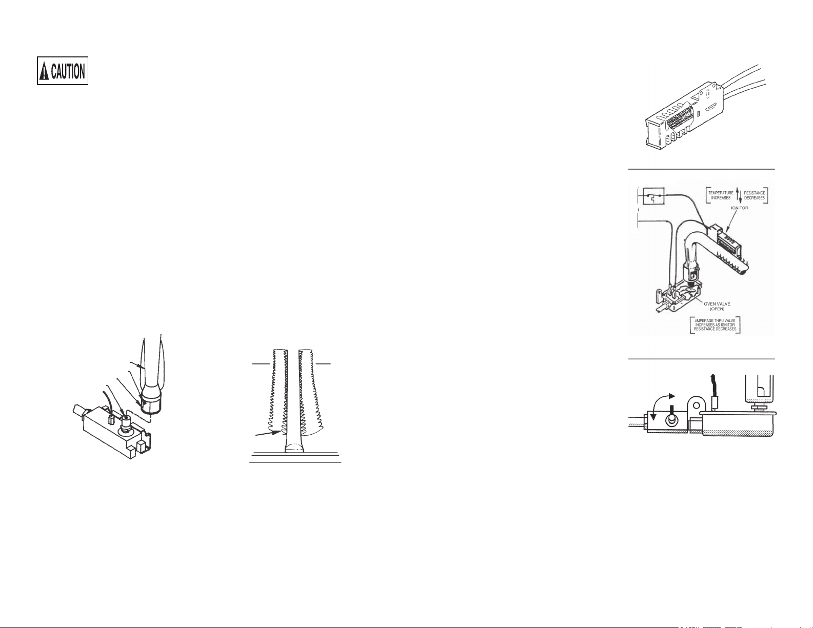
NORTON GLOWBAR
SERIES IGNITOR/VALVE CIRCUIT
SAFETY VALVE & SHUT-OFF
ON
OFF
L
N
THERMO STAT
"ON"