Loading ...
Loading ...
Loading ...
16
ALIGNMENTS AND ADJUSTMENT, Continued
5. Top Burner Valves
Top burner valves have orifices that are dedicated to the type of fuel to be used. These
orifices are not adjustable. They must be changed completely to convert from one gas to
the other. DO NOT DISCARD THE UNUSED ORIFICES. They should be saved in
order to convert the range back to its original fuel.
When converting the gas valves, the minimum flame adjustment screw must be adjusted
through the center of the valve stem. You will need a 3/32” flat blade screw driver to
make this adjustment. Hold the valve stem and turn the adjustment screw until the
proper flame of approximately 1/8” is obtained.
Adjust the air shutter, which is located on the throat of each burner, to obtain the proper
mixture of gas and air to create the proper sharp blue flame without a red or yellow tip.
The properly adjusted flame is approximately 3/4" high and has three distinct cones; the
kindling point, the dark blue center cone, and the outer mantel.
Standard Top Burner Valves
All top burner valves operate counterclockwise to open the valve and clockwise to close
the valve. To ignite gas, depress and turn the valve knob 90 degrees to the left to the
“LITE” position. You will feel a detent in the knob. This position is also the “HI”
position where the maximum gas flow rate is obtained, and the burner should light
automatically from the pilot flame. By turning the top burner knob past the “HI”
position, the valve can be adjusted to many different heat settings which should be
determined by the amount of food being cooked, the amount of liquid, or the size of the
utensil.
Top Burners with Pilotless Electric Spark Ignition
Ranges equipped with electric or battery spark ignition will have the top ignitor
electrodes in the same location as the familiar top burner standing pilots except for sealed
burner models that employ an ignitor for each burner. (See page 13 in the Owner’s
Manual.) To ignite the burner, depress and turn the valve knob 90 degrees to the left to
the “LITE” position. When a top burner knob is pressed, ALL electrodes will spark at a
rate of approximately 2 _ pulses (sparks) per second. Continue to hold the knob
depressed until gas ignites at the burner. Adjust the intensity of top burner heat in the
same manner described above.
In the event of a power failure, the top burners of electric ignition ranges can be lit by
holding a lighted match near the surface burner and turning on the surface burner.
ALIGNMENTS AND ADJUSTMENT, Continued
Top Burner Height
Make sure the top burners are properly positioned. The top of the burner head should be
level with the surface of the main top. To check, lay a straight edge such as a 12-inch
ruler across the burner bowl opening. The ruler should rest squarely on the top while in
contact with the burner head.
If the burner is too high (make sure the burner is cool), push it down. Supply enough
force with the palm of you hand to accomplish this adjustment. To raise, pull up on the
burner support at the center of the support.
6. Oven Control (Thermostat)
The oven control has a flame safety device built into the body of the thermostat.
Presence of a gas ignition source (pilot) is verified by a flame safety probe. This flame
safety probe actuates the internal safety device to allow gas into the oven burner when
the oven is turned on. If there is a loss of gas ignition during operation, the flame safety
device will close off gas flow to the oven burner and pilot.
The oven burner orifice is located on a brass injector stud at the rear of the oven under
the oven floor. This orifice is dedicated to the gas for which the oven is to be used. The
orifice is not adjustable. It must be changed completely to convert from one gas to the
other. DO NOT DISCARD THE UNUSED ORIFICE. It should be saved in order to
convert the range back to its original fuel.
When converting the oven thermostat to LP (Propane) gas, the minimum bypass screw
must be screwed in all the way until it tightens. To convert back to natural gas, turn the
screw counterclockwise until the minimum burner flames appear as a row of 1/8”
diameter dots along the side of the burner.
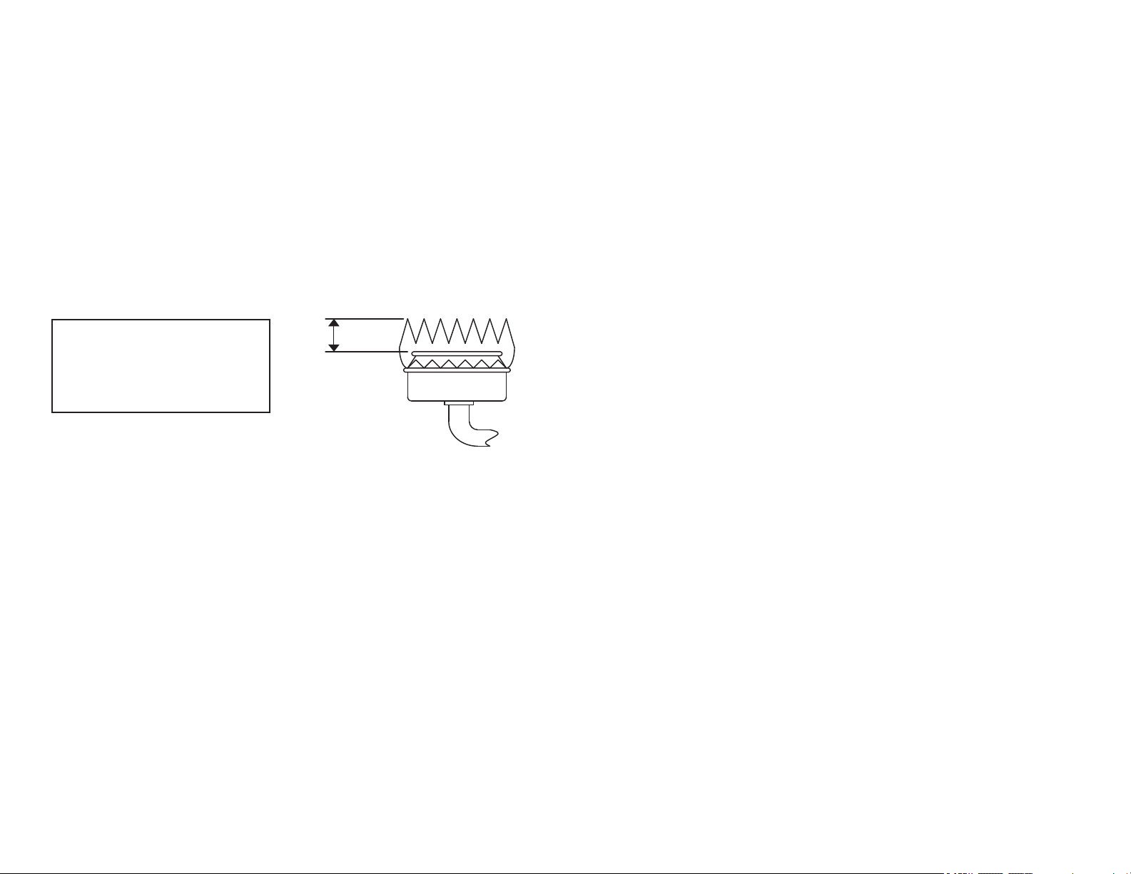
_” FLAME HEIGHT ON
“HIGH” SETTING
Note: “Full on” flame size illustrated.
The flame height in the “Low” position
should be approximately 1/8” high.
REMOVE SHIPPING SCREWS
FROM TOP BURNERS.
ALIGNMENTS AND ADJUSTMENT, Continued
5. Top Burner Valve
Top burner valves have orices that are dedicated to the type of fuel to be used. These
orices are not adjustable. They must be changed completely to convert from one gas to
the other. DO NOT DISCARD THE UNUSED ORIFICES. They should be saved in
order to convert the range back to its original fuel.
When converting the gas valves, the minimum ame adjustment screw must be adjusted
through the center of the valve stem. You will need a 3/32” at blade screw driver to
make this adjustment. Hold the valve stem and turn the adjustment screw until the
proper ame of approximately 1/8” is obtained.
Adjust the air shutter, which is located on the throat of each burner, to obtain the proper
mixture of gas and air to create the proper sharp blue ame without a red or yellow tip.
The properly adjusted ame is approximately 3/4" high and has three distinct cones; the
kindling point, the dark blue center cone, and the outer mantel.
Standard Top Burner Valves
All top burner valves operate counterclockwise to open the valve and clockwise to close
the valve. To ignite gas, depress and turn the valve knob 90 degrees to the left to the
“LITE” position. You will feel a detent in the knob. This position is also the “HI”
position where the maximum gas ow rate is obtained, and the burner should light
automatically from the pilot ame. By turning the top burner knob past the “HI”
position, the valve can be adjusted to many different heat settings which should be
determined by the amount of food being cooked, the amount of liquid, or the size of the
utensil.
Top Burners with Pilotless Electric Spark Ignition
Ranges equipped with electric or battery spark ignition will have the top ignitor
electrodes in the same location as the familiar top burner standing pilots except for sealed
burner models that employ an ignitor for each burner. (See page 13 in the Owner’s
Manual.) To ignite the burner, depress and turn the valve knob 90 degrees to the left to
the “LITE” position. When a top burner knob is pressed, ALL electrodes will spark at a
rate of approximately 2 _ pulses (sparks) per second. Continue to hold the knob
depressed until gas ignites at the burner. Adjust the intensity of top burner heat in the
same manner described above.
In the event of a power failure, the top burners of electric ignition ranges can be lit by
holding a lighted match near the surface burner and turning on the surface burner.
Note: “Full on” ame size illustrated.
The ame height in the “Low” position
should be approximately 1/8” high.
REMOVE SHIPPING SCREWS
FROM TOP BURNERS.
16
25
OPTIONAL EQUIPMENT
Continuous Cleaning Feature
If your oven has the continuous cleaning feature, it will have a dull gray nish with white
speckles that has been blended with a special catalytic material. (If the oven has a glossy
nish, it is standard porcelain enamel without the continuous cleaning feature.)
Before Using Your Oven–Read These Instructions Carefully.
Using The Continuous Cleaning Oven
The catalytic nish will keep your oven presentably clean with some effort on your part.
Any time the oven is in use, the catalytic action will be working to eliminate normal
cooking spatters. Simply cook as you usually do. Average oven spatters should fade away.
If a great deal of spattering occurs during cooking, a small amount may remain on the
surface of the oven interior at the end of the cooking time. This is particularly true during
a short cooking cycle. The longer the cooking cycle, the better the catalytic action.
Cleaning time depends on the type, size and amount of soil, and oven temperature. The
cleaning time will vary from a few minutes to several hours. The oven will never get
completely clean–it will appear “presentably clean,” even though some stains or spatters
may be present.
Heavy Spillovers–Unusual Stains
The continuous cleaning oven feature will make cleanups easy. However, some spills or
food types are harder for the oven to clean without a little assistance. For heavy spillovers,
such as from an overlled fruit pie or casserole, put a cookie sheet or aluminum foil on
the oven bottom. Be sure the foil does not cover the air openings, so do not extend foil
beyond oven bottom.
If you should get a heavy spillover on the oven bottom:
1. Brush off heavy soil with a nylon brush or plastic pad. DO NOT USE paper toweling,
cloths or sponge. Oven walls are porous and particles of these materials will rub off on
walls. Rinse area well with clean water only. Do not allow insulation under oven
bottom to become wet.
2. If spillovers harden before they can be wiped away, they may become either a brittle
crust or a varnish-type coating. The brittle crusts will loosen and ake off in time. This
process can be speeded up by GENTLY tapping crust with a wooden or plastic utensil
and then brushing crust away.
3. Any remaining soil will gradually reduce with continued oven use at normal baking
temperatures.
DO NOT USE ANY TYPE OF OVEN CLEANER, POWERED CLEANSERS, SOAP,
DETERGENT OR PASTE ON ANY CONTINUOUS CLEANING SURFACE. ALSO,
DO NOT USE ANY ABRASIVE MATERIALS, STEEL WOOL, SHARP
INSTRUMENTS OR SCRAPERS. THEY WILL DAMAGE THE FINISH.
NOTE: Over a period of time, wear marks may appear on the embossed rack supports. This
is normal and results from sliding the oven racks in and out of the oven. Wear marks will
not interfere with the overall cleaning action of the oven.
Loading ...
Loading ...
Loading ...