Loading ...
Loading ...
Loading ...
26
Electrical Grounding Instructions: This Appliance must be properly
grounded and must be connected as shown in gure 1, 2 or 3 on page 11.
Do not alter wiring or electrical equipment.
The backguard equipment is optional, depending on model selection. The range you have
purchased may or may not be equipped with the features that are illustrated in this section.
The clocks have been placed into separate groups.
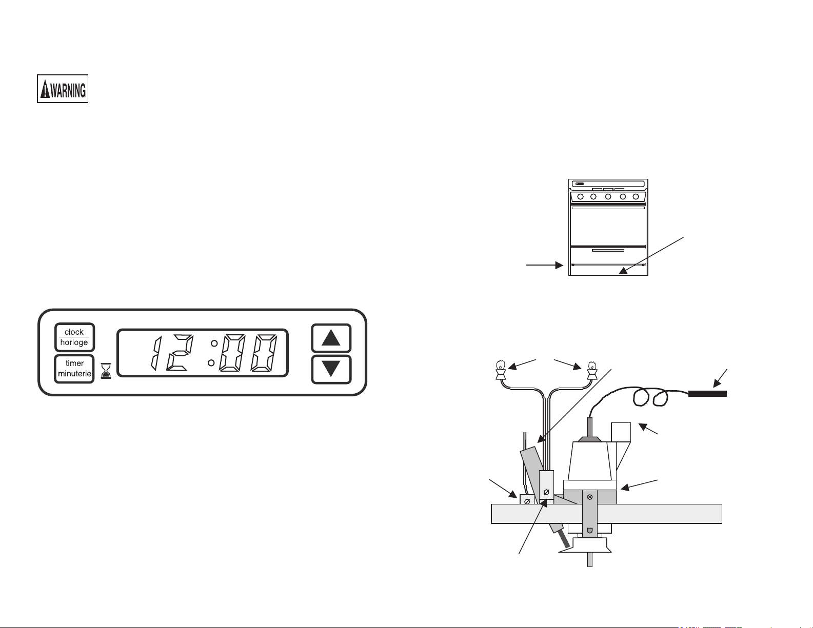
DIGITAL CLOCK WITH TIMER
To set “time of day” press CLOCK. Press or to set correct time.
To set “cook time” press TIMER (0:00 WILL APPEAR). Press to set minutes (12 HRS
IS MAXIMUM TIMER SETTING). Then press TIMER again.
Colon starts blinking indicating timer is counting down.
To clear timer press TIMER.
To return to clock while timer is running, Press CLOCK.
OPTIONAL EQUIPMENT, continued
Background and Control Panel Features
15
ALIGNMENTS AND ADJUSTMENT, Continued
3. Battery Replacement (If Equipped)
Ranges with the modulated battery spark standby pilot ignition system require two (2) 9
volt alkaline batteries for operation. These batteries are located within the “kick plate”
enclosure just below the broiler drawer. It is recommended that you check and/or replace
these batteries at least once per year.
Access to the batteries is done as follows:
• Use a Phillips screwdriver to remove the two (2) kick plate screws.
• Gently lower the kick plate to reveal the batteries held in place by spring clips.
• Check and/or replace the batteries as recommended.
• Reinstall the kick plate with the two (2) Phillips screws.
4. Top Pilots (If Equipped)
The top burner pilots can be adjusted by a screw located on the pilot filter attached on the
rear face of the manifold pipe. Adjust the pilot flame until there is only a slight tip of
yellow on the flame. Pilots are constant burning. DO NOT BLOW OUT FLAME
WITHOUT TURNING OFF PILOT ADJUSTMENT SCREW.
ALIGNMENTS AND ADJUSTMENT, Continued
5. Top Burner Valves
Top burner valves have orifices that are dedicated to the type of fuel to be used. These
orifices are not adjustable. They must be changed completely to convert from one gas to
the other. DO NOT DISCARD THE UNUSED ORIFICES. They should be saved in
order to convert the range back to its original fuel.
When converting the gas valves, the minimum flame adjustment screw must be adjusted
through the center of the valve stem. You will need a 3/32” flat blade screw driver to
make this adjustment. Hold the valve stem and turn the adjustment screw until the
proper flame of approximately 1/8” is obtained.
Adjust the air shutter, which is located on the throat of each burner, to obtain the proper
mixture of gas and air to create the proper sharp blue flame without a red or yellow tip.
The properly adjusted flame is approximately 3/4" high and has three distinct cones; the
kindling point, the dark blue center cone, and the outer mantel.
Standard Top Burner Valves
All top burner valves operate counterclockwise to open the valve and clockwise to close
the valve. To ignite gas, depress and turn the valve knob 90 degrees to the left to the
“LITE” position. You will feel a detent in the knob. This position is also the “HI”
position where the maximum gas flow rate is obtained, and the burner should light
automatically from the pilot flame. By turning the top burner knob past the “HI”
position, the valve can be adjusted to many different heat settings which should be
determined by the amount of food being cooked, the amount of liquid, or the size of the
utensil.
Top Burners with Pilotless Electric Spark Ignition
Ranges equipped with electric or battery spark ignition will have the top ignitor
electrodes in the same location as the familiar top burner standing pilots except for sealed
burner models that employ an ignitor for each burner. (See page 13 in the Owner’s
Manual.) To ignite the burner, depress and turn the valve knob 90 degrees to the left to
the “LITE” position. When a top burner knob is pressed, ALL electrodes will spark at a
rate of approximately 2 _ pulses (sparks) per second. Continue to hold the knob
depressed until gas ignites at the burner. Adjust the intensity of top burner heat in the
same manner described above.
In the event of a power failure, the top burners of electric ignition ranges can be lit by
holding a lighted match near the surface burner and turning on the surface burner.
Thermostat
Manifold Pipe
Top Burner Pilots
Thermostat
Sensor
Top pilots
adjustment screw
controls rate of gas
to top burner pilots.
Oven pilot
adjustment screw
controls rate of
gas to oven pilot.
Main Oven Gas
Connection
Safety Thermocouple
Connection
Screw Locations
Kick Plate
ALIGNMENTS AND ADJUSTMENT, Continued
4. Battery Replacement (If Equipped)
Ranges with the modulated battery spark standby pilot ignition system require two (2) 9
volt alkaline batteries for operation. These batteries are located within the “kick plate”
enclosure just below the broiler drawer. It is recommended that you check and/or replace
these batteries at least once per year.
Access to the batteries is done as follows:
• Use a Phillips screwdriver to remove the two (2) kick plate screws.
• Gently lower the kick plate to reveal the batteries held in place by spring clips.
• Check and/or replace the batteries as recommended.
• Reinstall the kick plate with the two (2) Phillips screws.
15
4. Top Pilots (If Equipped)
The top burner pilots can be adjusted by a screw located on the pilot lter attached on the
rear face of the manifold pipe. Adjust the pilot ame until there is only a slight tip of
yellow on the ame. Pilots are constant burning. DO NOT BLOW OUT FLAME
WITHOUT TURNING OFF PILOT ADJUSTMENT SCREW.
Loading ...
Loading ...
Loading ...