
Loading ...
Loading ...
Loading ...
©
2020 DJI All Rights Reserved.
33
ROBOMASTER EP Core User Manual
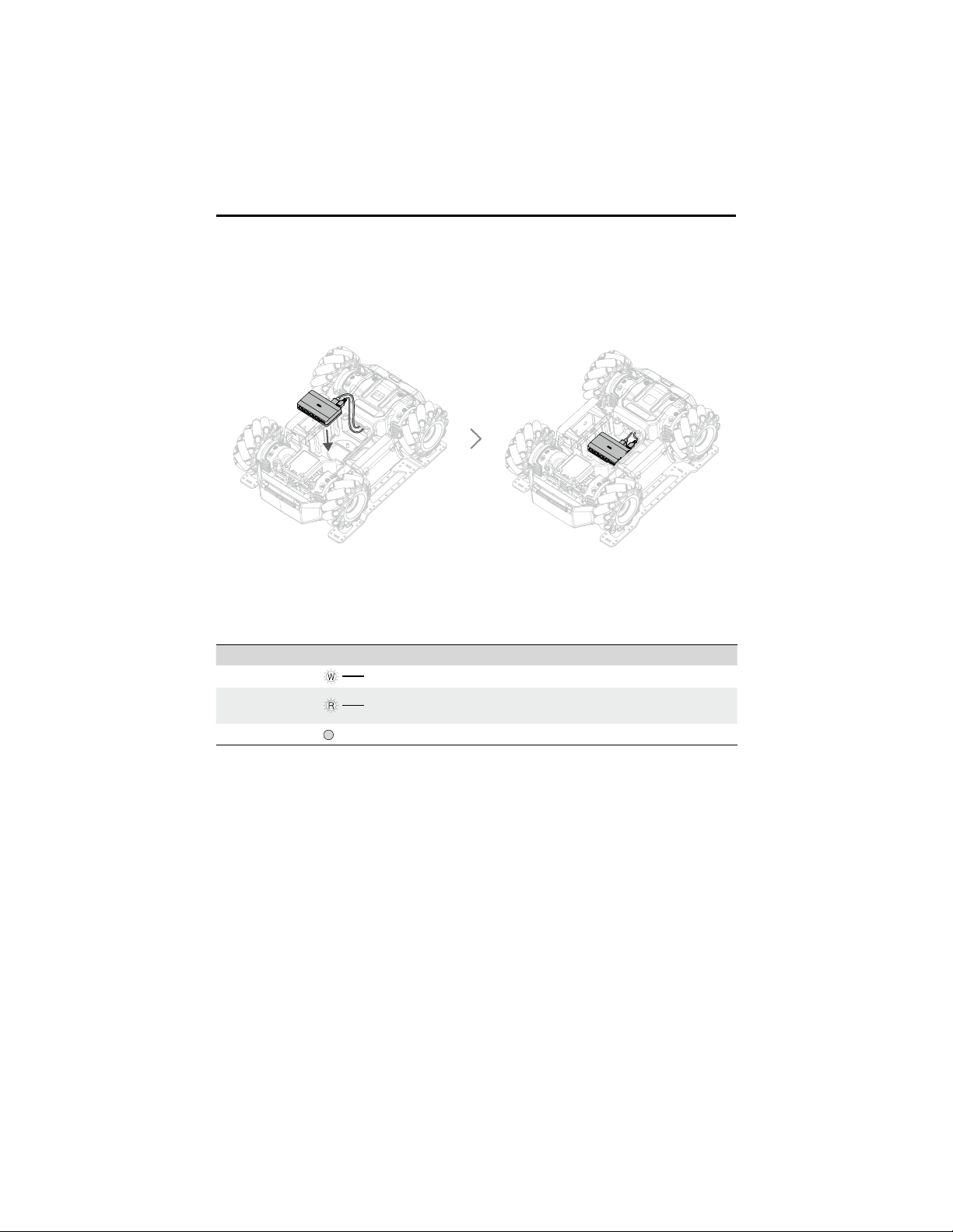
5. As shown below, connect the XT30 power cable in the chassis cabin to the 12V power input
port and the B end of the 12cm data cable to the CAN bus port of the power connector module.
Secure the module at the chassis cabin.
LED Indicator Description for Power Connector Module
The LED indicator is used to indicate the status of the power connector module. Details are as
follows:
LED Indicator Power Connector Module Status
Solid white
Normal power input and 5V output
Solid red
Normal power input, but 5V output has an overcurrent or
is short-circuited
Off
Abnormal power input
Loading ...
Loading ...
Loading ...