
Loading ...
Loading ...
Loading ...
©
2020 DJI All Rights Reserved.
31
ROBOMASTER EP Core User Manual
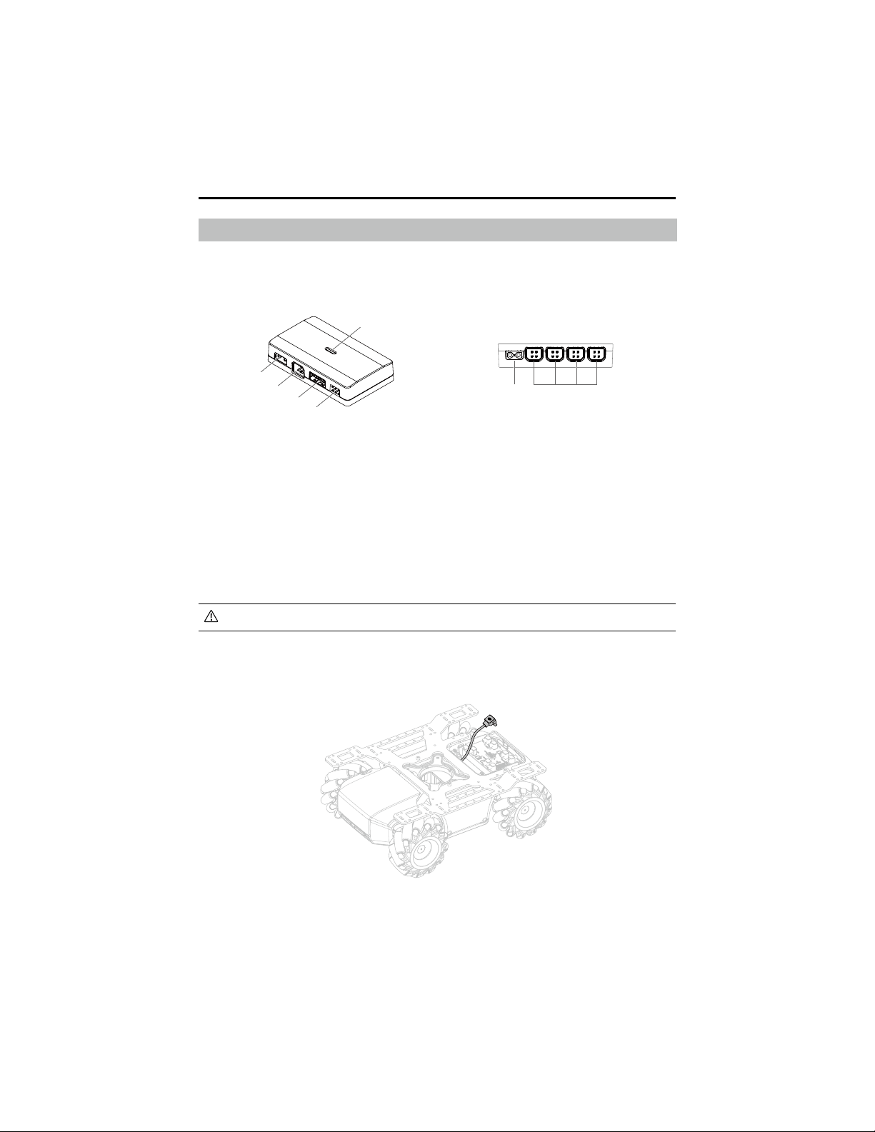
Power Connector Module
Introduction
A power connector module can connect and power third-party hardware, offering multiple ports to
connect hardware and create custom programs and applications.
If both 5V power output ports are used, the module supports a current output of up to 4 A.
Mounting the Power Connector Module
1. Unplug the power cable of the motion controller.
1. 12V Power Input Port
The input voltage is 9.6-12.6 V.
2. CAN Bus Port
Connect with CAN bus cable.
3. 5V/2A Power Output Port
The output voltage is 5 V and supports a
current output of up to 2 A.
4. 5V/4A Power Output Port
The output voltage is 5 V and supports a
current output of up to 4 A.
5. LED Indicator
Indicates the status of the power connector
module.
6. 12V Conducting Power Output Port
Conducts power along with the 12V power
input port.
1
2
6 2
3
4
5
Loading ...
Loading ...
Loading ...