User Manual Waterproof Keypad
CARTON INVENTORY

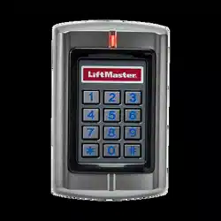
KPR2000
Keypad/Proximity Reader/Controller

Diode IN4007 (For Relay circuit protection)

Self Tapping Screws #8 x 1"

Wall Anchors #6 x 1 1/8"

Security Screwdriver
(T-10 Security Torx Driver)

Manager Add Card

Manager Delete Card
NOTICE: This device complies with part 15 of the FCC rules and Industry Canada (IC) license-exempt RSS standard(s). Operation is subject to the following two conditions: (1) this device may not cause harmful interference, and (2) this device must accept any interference received, including interference that may cause undesired operation.
Any changes or modifications not expressly approved by the party responsible for compliance could void the user’s authority to operate the equipment.
This Class B digital apparatus complies with Canadian ICES-003.
This device must be installed in a way where a minimum 8" (20 cm) distance is maintained between users/ bystanders and device.
This device has been tested and found to comply with the limits for a Class B digital device, pursuant to part 15 of the FCC rules. These limits are designed to provide reasonable protection against harmful interference in a residential installation. This equipment generates, uses and can radiate radio frequency energy and, if not installed and used in accordance with the instructions, may cause harmful interference to radio communications.
However, there is no guarantee that interference will not occur in a particular installation. If this equipment does cause harmful interference to radio or television reception, which can be determined by turning the equipment off and on, the user is encouraged to try to correct the interference by one or more of the following measures:
- Reorient or relocate the receiving antenna.
- Increase the separation between the equipment and receiver.
- Connect the equipment into an outlet on a circuit different from that to which the receiver is connected.
- Consult the dealer or an experienced radio/TV technician for help.
INSTALL THE KPR2000
The KPR2000 fits a standard single outlet box, or a 2.4" (6.1 cm) square pedestal mount.

CHOOSE AN OPERATION MODE
STAND ALONE OPERATION (KPR2000 WITH A GATE OPERATOR)
The KPR2000 functions as a complete access control system. The user database is stored in non-volatile memory, reads the PINs and card codes, performs the authentication, and grants and monitors access to the property or device. In Stand Alone Operation there are three different Access Configurations listed below:
- Card or PIN (Default): The User must present a valid Wiegand Card to the KPR2000 or enter their PIN code followed by the # key, in order to be granted access.
- Card Only: The User must present a valid Wiegand Card to the KPR2000 in order to be granted access. The facility code and the ID number are both read and validated as one block of Wiegand data.
- Card + PIN: The User must first present a valid Wiegand Card to the KPR2000 and then enter their PIN code followed by the # key, in order to be granted access.
PASS-THROUGH OPERATION (KPR2000 WITH TELEPHONE ENTRY SYSTEM)
The KPR2000 passes all keypad and card reader Wiegand data to an external controller. The KPR2000 should be in the “Card or PIN” access configuration for pass-through operation. In this mode the LED will stay red, and the KPR2000 will beep 3 times when credentials are presented that are authenticated to the external controller. To change this mode and allow the KPR2000 to flash the green LED, and beep 1 time, the KPR2000 will have to learn the same credentials as the external controller.
IMPORTANT NOTE: Both modes of operation support Auto User ID generation (simplest method) and manual entry of user ID.
KEYPAD OPERATION
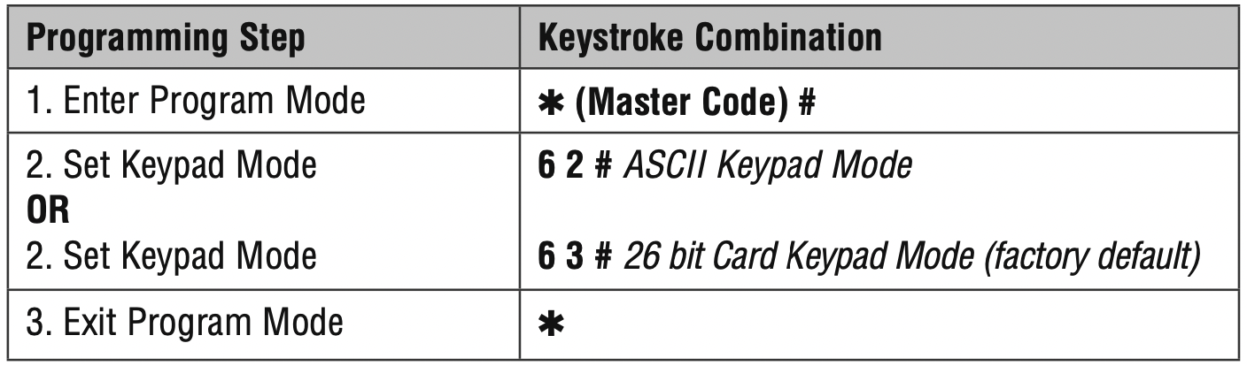
The KPR2000 keypad may output an 8 bit ASCII code every keystroke, or output a 26 bit Wiegand card packet with a facility code and a 4-5 digit card number when the # key is pressed. See configuration options on page 11.
WIRE THE KPR2000
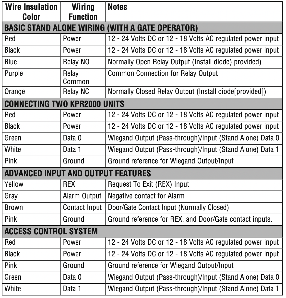
WIRING EXAMPLES:
Connecting to an Access Control System
The example below uses the EL25/EL2000SS Wiegand Module (WOMDKT). KPR2000 can be connected to other access systems with the same Wiegand inputs. KPR2000 can be connected to Device 1, 2, 3 or 4 (EL25, EL2000SS).
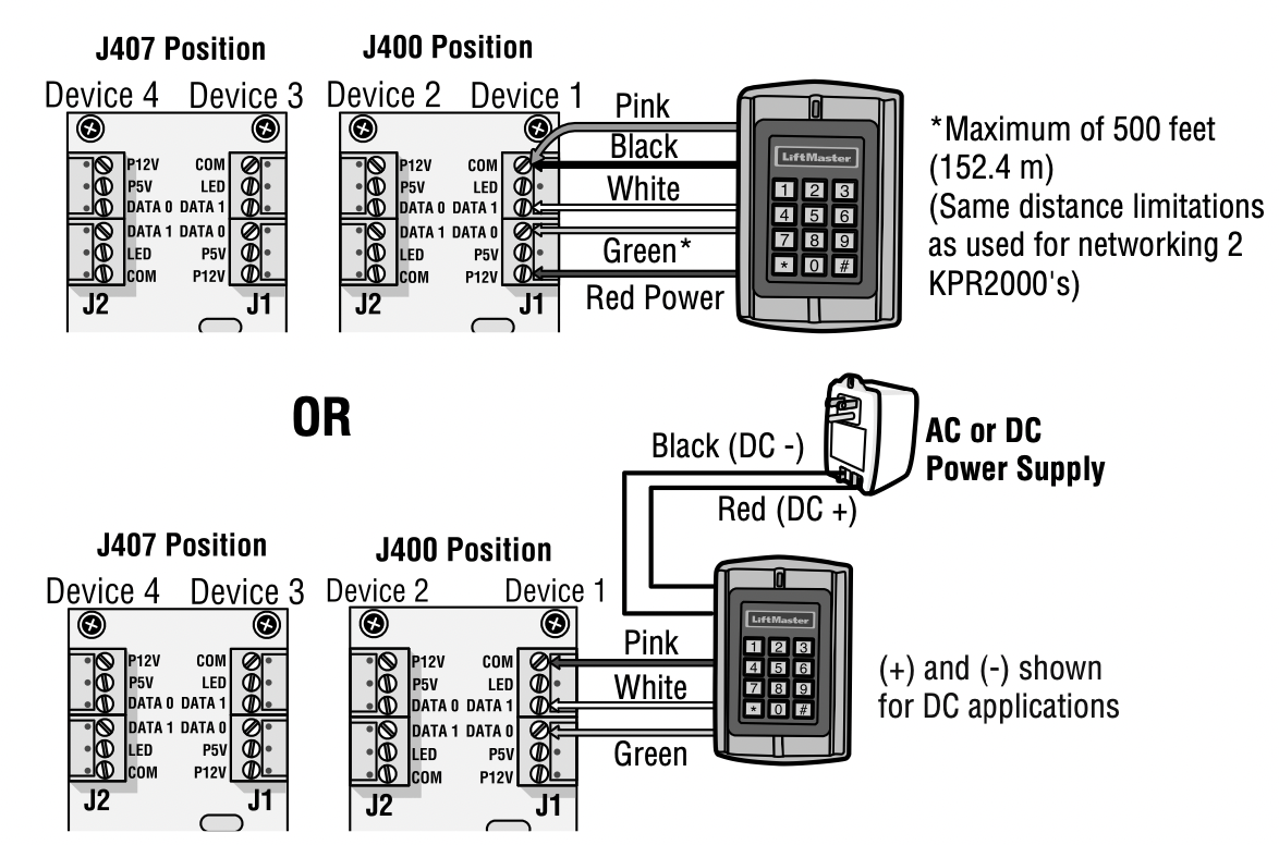
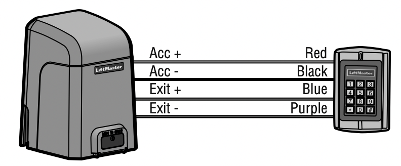
Connecting to a Gate Operator
4-wire connection with KPR2000 powered from the CSL24U/CSW24U/LA500PKGU/ LA400PKGU accessory power output.
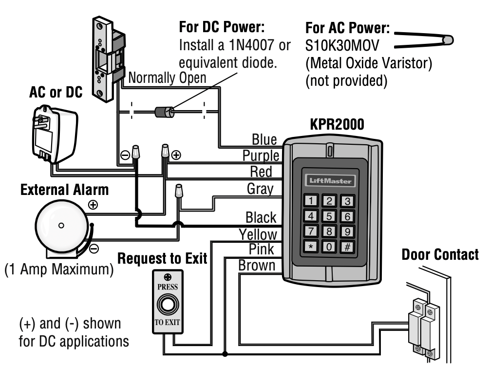
Door Operator or Fail-Secure Strike
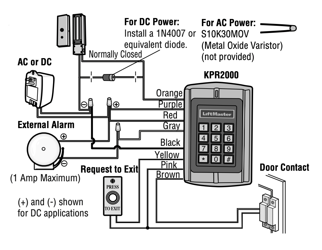
Magnetic Lock or Fail-Safe Strike
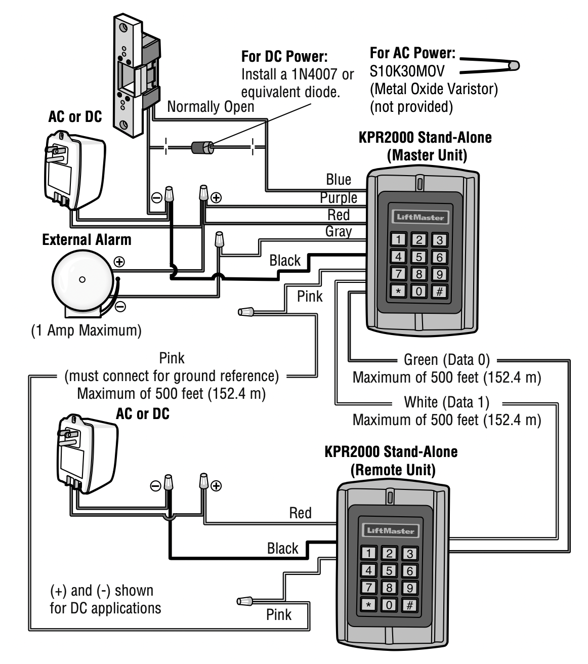
Networking Two KPR2000 Units
Change the configuration settings according to your application (optional). Multiple configuration settings can be changed at one time: enter program mode, change desired settings, then exit program mode.
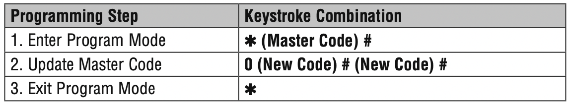
SET MASTER CODE
The 6 digit Master Code is used to prevent unauthorized access to the system. To interface with the KPR2000, the manager will need a Master Code (factory default code: 888888). We highly recommend immediate update and recording of your Master Code.
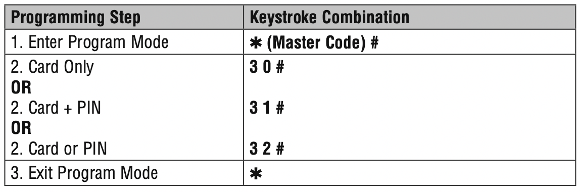
SET ACCESS CONFIGURATION
NOTE: See page 6 for description of each operation mode.
There are 3 types of access configurations for the KPR2000:
Card or PIN (Default): The User must present a valid Wiegand Card to the KPR2000 or enter their PIN code followed by the # key, in order to be granted access.
Card Only: The User must present a valid Wiegand Card to the KPR2000 in order to be granted access. The facility code and the ID number are both read and validated as one block of Wiegand data.
Card + PIN: The User must first present a valid Wiegand Card to the KPR2000 and then enter their PIN code followed by the # key, in order to be granted access.
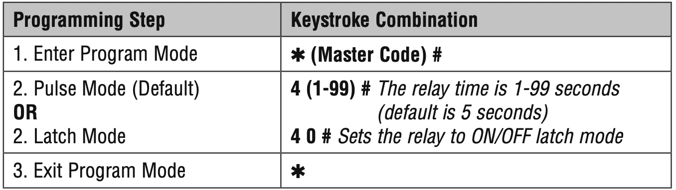
SET RELAY CONFIGURATION
The relay configuration sets the behavior of the output relay on activation.
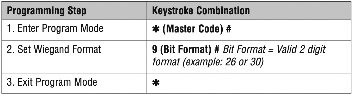
SET WIEGAND INPUT/OUTPUT OPTIONS
The KPR2000 offers input and output for industry standard Wiegand devices (refer to Specifications). Default is HID 26 bit.
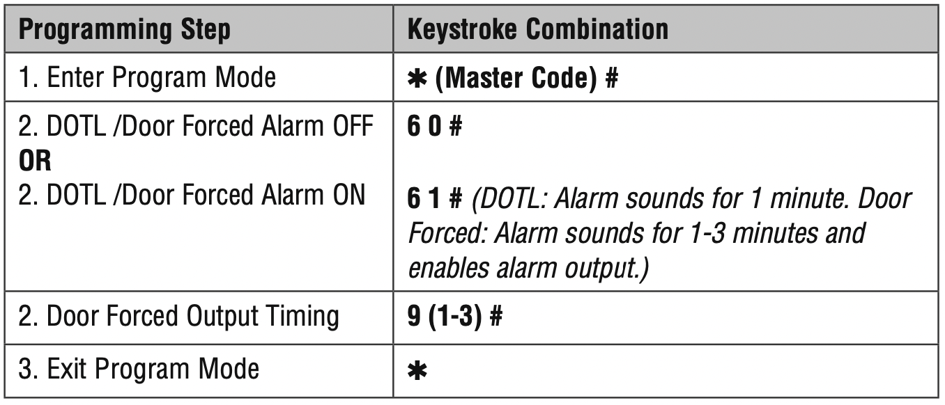
SET DOOR OPEN TOO LONG (DOTL) OR FORCED ALARM
This setting enables both DOTL and Door Forced Alarms and requires an external sensor input. The Door Forced alarm output timing can be set from 1-3 minutes (default is 1 minute). The Door Open Too Long (DOTL) timing is fixed to 1 minute and only sounds the built in buzzer. Factory default is OFF.
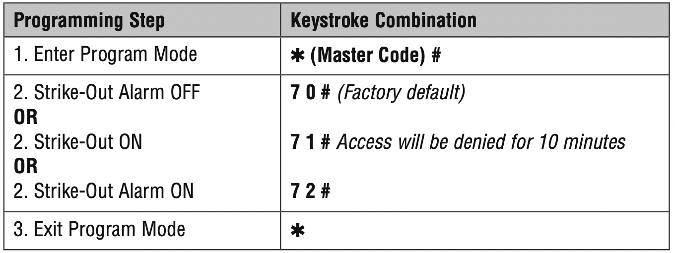
SET STRIKE-OUT ALARM
The strike-out alarm will engage after 10 failed card/PIN attempts in a ten minute period. Factory default is OFF. The strike-out alarm can be set to deny access for 10 minutes or it can be set to operate the alarm for 10 minutes.
NOTE: Enter Master Code or Valid Card to silence all alarm outputs.
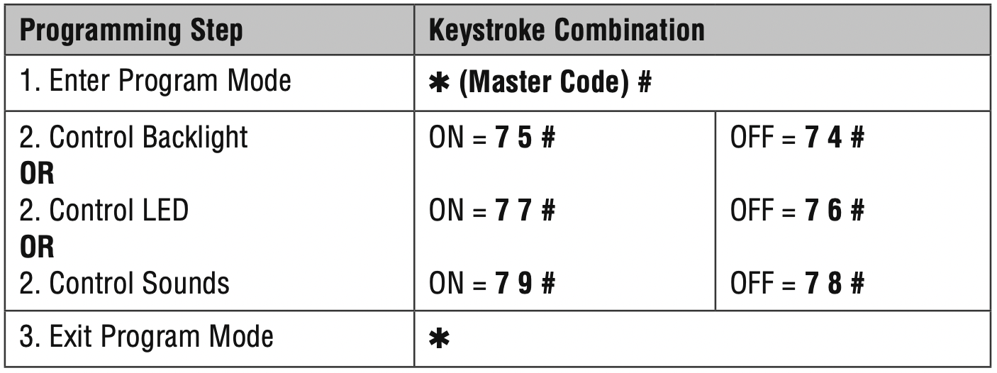
SET AUDIBLE AND VISUAL RESPONSE
Factory default is ON.
SET WIEGAND KEYPAD MODE
SET 26 BIT FORMAT FACILITY CODE
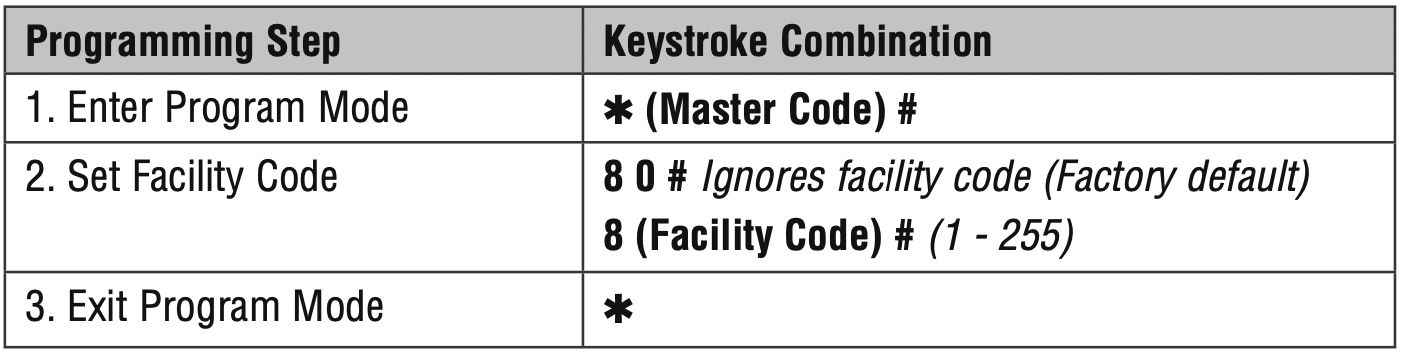
PROGRAM CARDS AND PINS
Programming will vary depending on the access configuration.
Follow the instructions according to your access configuration.
GENERAL PROGRAMMING INFORMATION
- User ID Number: Assign a user ID number to the access code in order to keep track of the users of access cards or PINs. The user ID number can be any number from 1-2000.
IMPORTANT: User IDs do not have to be proceeded with any leading zeros. Recording of User ID is critical. Modifications to user data require either the card or the User ID be available. - Proximity Card: Any 125 KHz industry standard 26 bit Wiegand Proximity Card, or 30 bit Sentex Proximity Card.
- Keypad PIN: The PIN can be any 4 - 5 digits between 0000 - 65535 (except 1234 which is reserved for factory testing). IMPORTANT: PINs less than 1000 must be preceded with leading zeros. PINs greater than 999 do not require any leading zeros.
EXAMPLES:
PIN code 15 = 0015
PIN code 25 = 0025
PIN code 9999 = 9999
PIN code 65431 = 65431 - All card users are automatically assigned a default PIN of 1234 that must be changed to be activated.
ACCESS CONFIGURATION: CARD OR PIN, CARD + PIN, & CARD ONLY
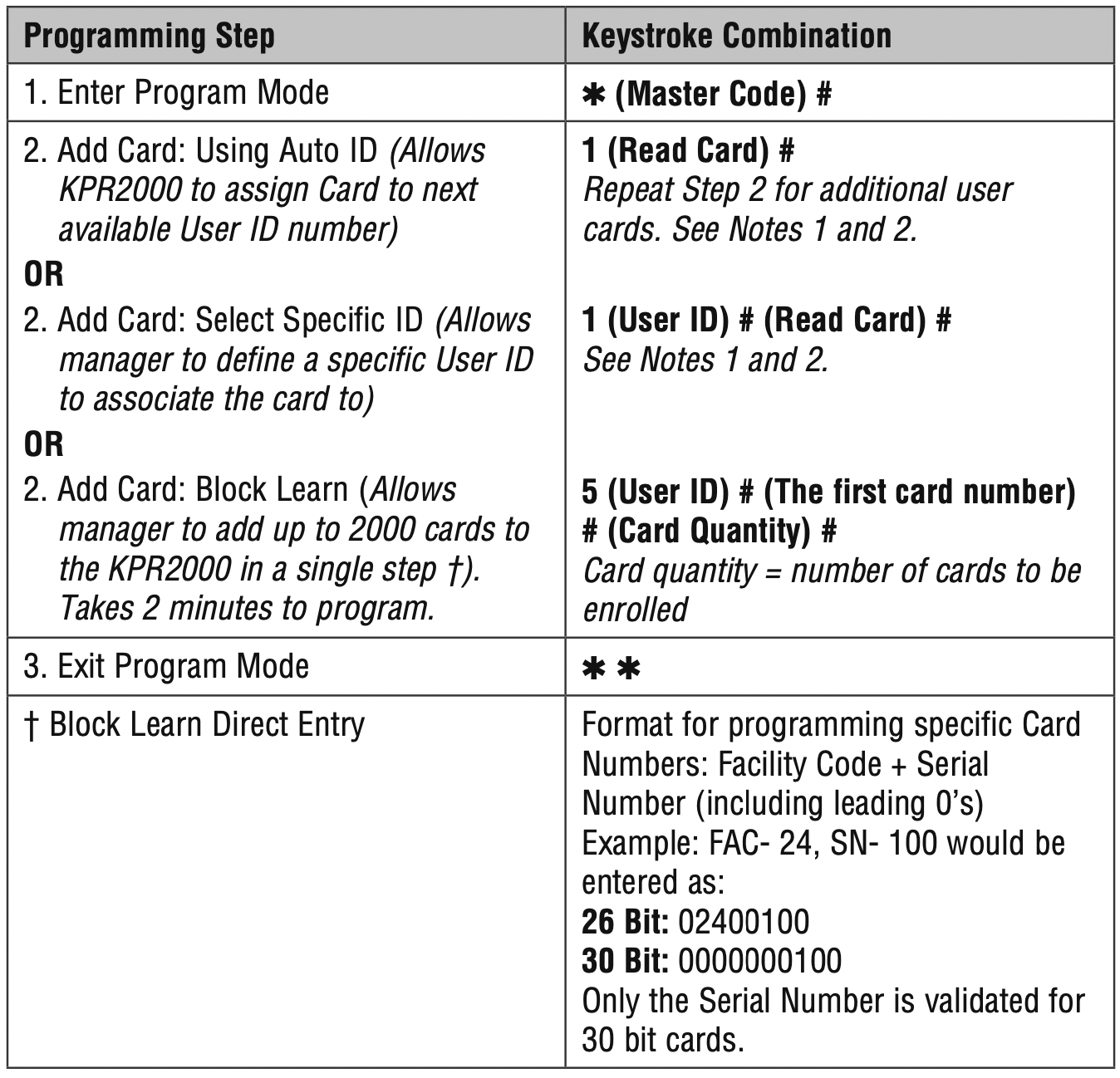
ADD USER CARD(S)
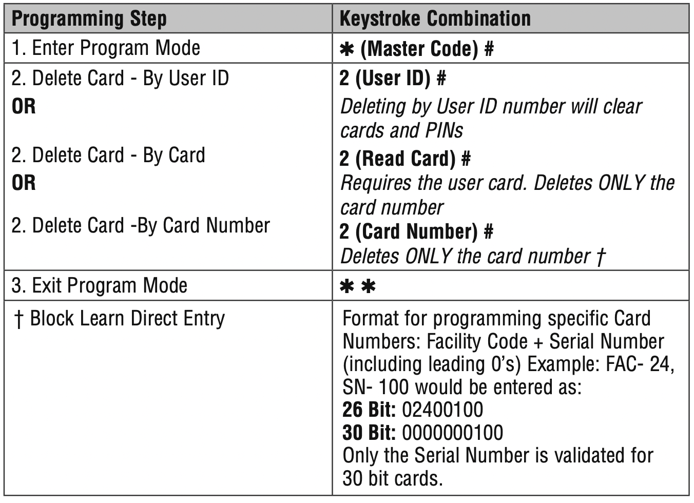
DELETE USER CARD(S)
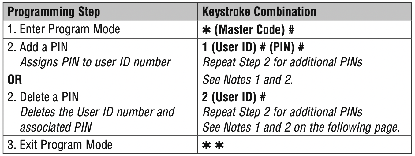
ADD OR DELETE A PIN
A PIN may be programmed to a separate or an existing user ID. PINs programmed separately will use additional memory.
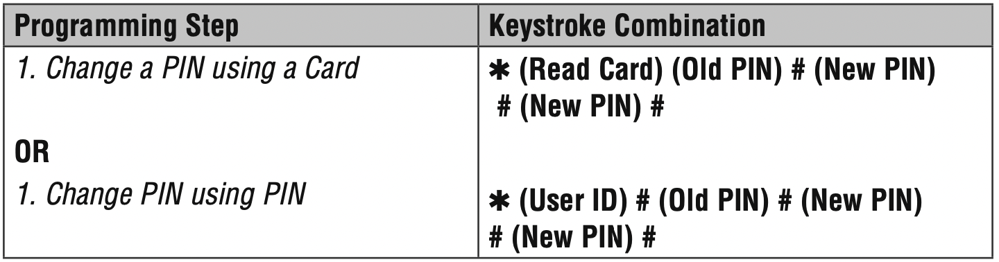
CHANGE A PIN
Allows card user to update a previously set PIN for a card & PIN or card + PIN User ID. Default PIN codes (1234) can only be changed by using Change PIN using a card.
NOTE: This operation is executed from outside of Program Mode.
NOTE 1: When assigning a user both a card and a PIN, the card MUST be assigned first. After the card is assigned, the user must change the PIN using card to activate the PIN for this user. If the PIN is assigned first, a second user ID must be used to assign the card.
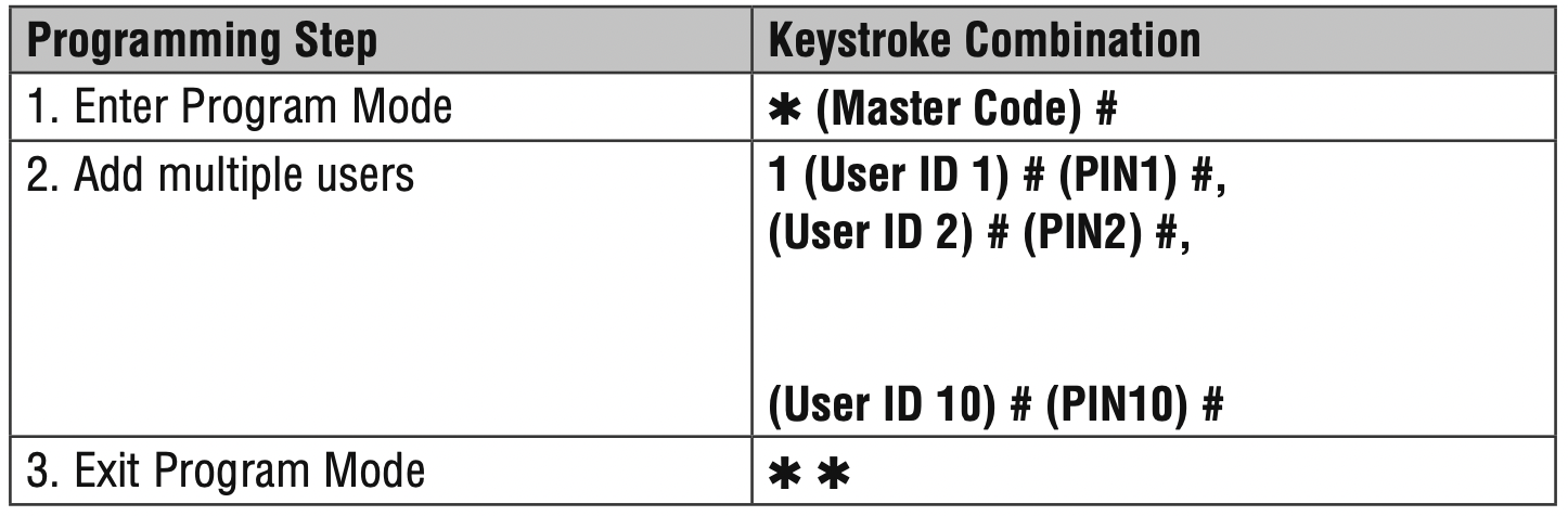
NOTE 2: When adding or deleting multiple users sequentially, the program command (1 or 2, respectively) is entered only once at the beginning of the procedure. For additional users, enter the user ID and credentials only in the same order as the first entry. When sequence is complete, programming step is terminated by pressing ✱ once.
EXAMPLE: To Add Multiple Users
ACCESS CONFIGURATION: CARD ONLY
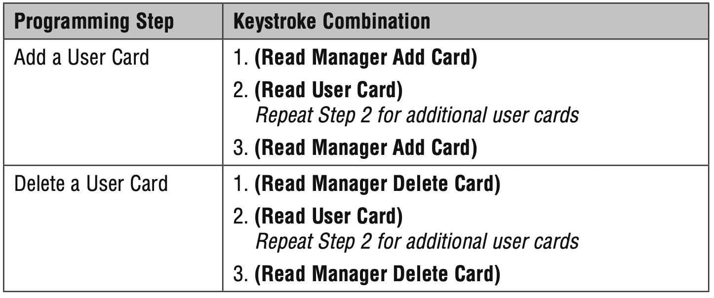
USING MANAGER CARDS
KPR2000 managers can use manager cards to program user cards into and out of the system. There are two pre-programmed manager cards (an Add Card, and a Delete Card) to allow rapid card enrollment. This is a form of Auto User ID enrollment and is only available in “Card Only” configuration.
ALARM
TO RESET THE ALARM

ANTI-TAMPER ALARM
The KPR2000 uses an optical sensor as the input for its internal alarm. If the case is opened while the KPR2000 is powered, the alarm will operate. Enter Master Code or a valid card to silence all alarm outputs.
RESET THE KPR2000
This will reset the KPR2000 to the factory default but all card/PIN information will still be retained. This will also require reprogramming of the Master Add and Delete Cards.
NOTE: This is useful if the original Master Add and Delete Cards have been lost.

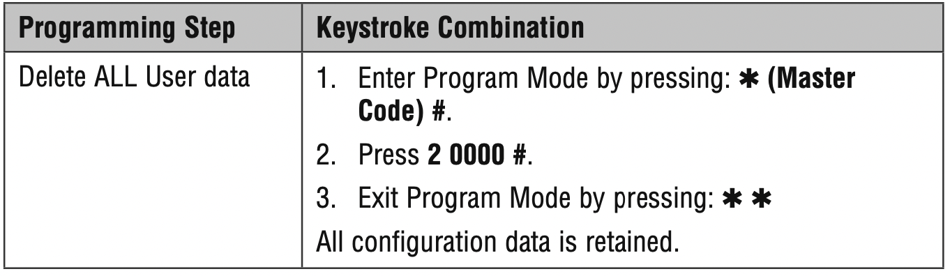
ERASE ALL CODES
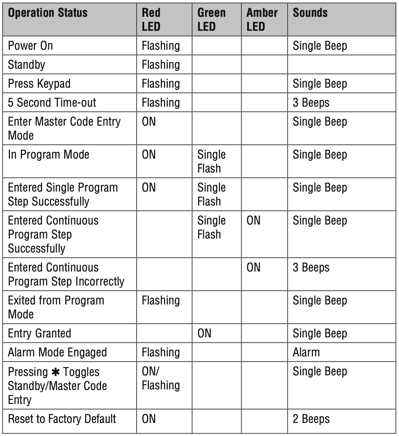
SOUND & LIGHT INDICATION