Loading ...
Loading ...
Loading ...
23
INSTALLATION INSTRUCTION
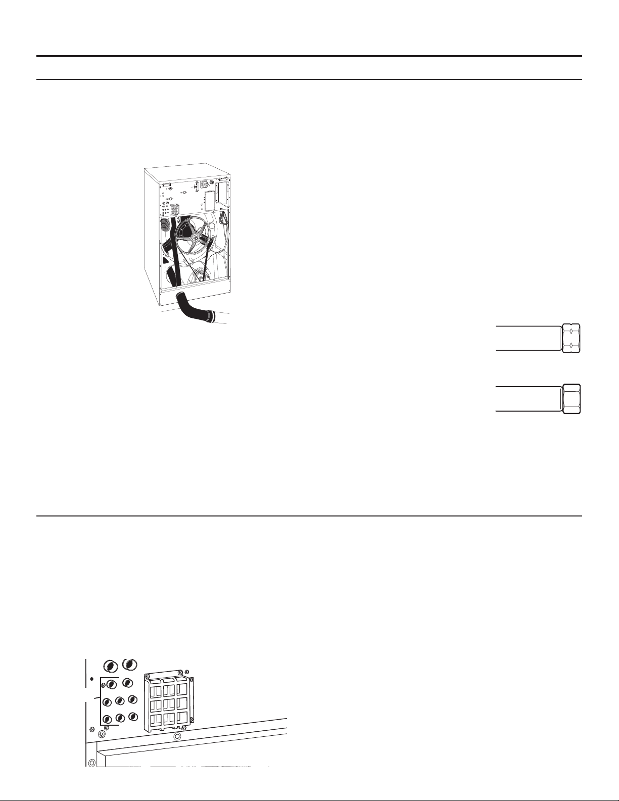
Connect the Drain Hose
1. The drain hose can be found shipped inside the drum
with the installation kit. The clamp for this hose is in the
installation kit. Attach the drain to the drain connection
located near the bottom of the rear of the washer. This is a
gravity-fed system, so you must install the drain hose with
the outlet lower than the drain connection to ensure proper
drainage. Do not kink the hose.
Drain Hose
2. The drain hose should end over, or in a floor drain or
drainage canal.
3. The drainage canal or drain pipe must be sized properly
to handle the total output of all washers connected to the
system. Each time a washer is added to the drain pipe,
the size of the pipe must increase to accommodate the
additional volume. The drain pipe at the first washer must
be 3" (76 mm) diameter. The pipe must increase to
4" (100 mm) diameter before the second washer and
5" (127 mm) diameter before the third washer.
4. For connecting the optional drain pump kit (Ordered
separately) refer to the instructions supplied with that kit.
Drain Connections
Use the provided drain hose to connect the washer’s drain pipe
to the facility drain or drain channel. Secure with the provided
clamp. The capacity of discharged water for each washer model
is 55.5 gal/min (210 L/min).
Water Hardness
Determine the water hardness level in water supply. Good wash
results are dependent on water hardness. In areas that have
medium and very hard water levels, a water softener may be
required.
Contact your water or soap distributor for determining the proper
soap and detergents to be used with your hardness levels for the
best wash results.
Water Supply Connections
Washers have 2 water inlets. For connection dimensions, see
“Dimensions and Technical Specications.”
1. Always use the exible hoses delivered with the washer. Do
not use a xed connection to the water supply.
2. Keep proper water pressure within range. See “Dimensions
and Technical Specifications.”
3. The water connection to the washer
requires a 3/4" British Standard Pipe
Thread fitting. The grooved end is a
U.S. thread. Threading an GHT
fitting or the GHT end of the
adapter hose will damage the
threads of the washer.
4. Flush water lines to remove debris.
Install the grooved side of the
adapter hoses to the hot and cold
side of the valves. Tighten fittings.
5. Attach non-grooved end of
adapter hoses to the washer. (On
55R, 55S, 65R, and 65S models,
there is a hose screen included in
the installation kit that needs to be placed here).
Tighten fittings.
6. Turn on water and check for leaks in the system.
External Supply Connections
All external liquid soap hose connections must be tight. Double
check that the clamps are tight after connections are made.
Make sure any unused open connections are sealed with an
appropriate cover.
The connections for the liquid soap are on the rear of the
washer and must be drilled open in order to use them. Only
drill out the connections that will be used. There are eight (8)
3/8" (9 mm) diameter connections; use a 5/16" (8 mm) diameter
drill bit to drill out these holes. There can only be eight (8)
pumps in the system. Be sure to clean out all the drill shavings
completely so they do not clog the inlets and hoses. Connect to
liquid soap pumps to the left openings rst. Set the ow rate of
the pumps between 16 and 26 gal/hr (60 and 100 l/hr).
IMPORTANT: The incoming water dilutes the liquid soap and
brings it into the tub assembly.
Check with your liquid soap provider to ensure that your
soap is inert to Polypropylene (PP) and Polyvinyl Chloride (PVC)
materials.
Make sure the hoses and wiring for the liquid soap pumps are
not damaged, pinched, rubbed or damage to the machine could
occur.
The liquid soap pumps used must be capable of providing the
requested quantity in less than 30 seconds.
3/4" Garden
Hose (GHT) tting
3/4" British Standard
Pipe Thread (BSPP)
tting
Liquid Soap
Connections
Loading ...
Loading ...
Loading ...