Home
Bookmarks
Home
Binder
Binder UF V 700 User Manual
Page 110
Binder UF V 700 UF V 500-liter Ultra Low Temperature Freezer
User Manual - Page 110
For UF V 700.
PDF File Manual
,
119 pages
,
Read Online
|
Download pdf file
1. Safety
1.1 Personnel Qualification
1.2 Operating manual
1.3 Legal considerations
1.4 Structure of the safety instructions
1.4.1 Signal word panel
1.4.2 Safety alert symbol
1.4.3 Pictograms
1.4.4 Word message panel structure
1.5 Localization / position of safety labels at the chamber
1.6 Type plate
1.7 General safety instructions on installing and operating the chamber
1.8 Intended use
1.9 Foreseeable Misuse
1.10 Residual Risks
1.11 Operating instructions
1.12 Measures to prevent accidents
2. Chamber description
2.1 Chamber overview
2.2 Door lock and controller housing
2.2.1 Operating the NumPad (option âDoor access systemâ)
2.2.2 Operating the electromechanical door locking (option âDoor access systemâ)
2.3 Main power switch
2.4 Chamber rear
2.5 Doors
2.5.1 Outer door
2.5.2 Compartment doors
2.6 Drain well for condensate during defrosting (option)
3. Completeness of delivery, transportation, storage, and installation
3.1 Unpacking, and checking equipment and completeness of delivery
3.2 Guidelines for safe lifting and transportation
3.2.1 Moving the freezer inside a building
3.2.2 Transport outside a building
3.3 Storage
3.4 Location of installation and ambient conditions
4. Installation and connections
4.1 Operating instructions
4.2 Spacers for rear wall distance
4.3 Adjustable shelves
4.4 Connections of cooling water for chambers with water cooling
4.4.1 Connection of cooling water outlet for water cooling
4.4.2 Connection of cooling water inlet for water cooling
4.4.3 Connection kit for cooling water
4.5 Electrical connection
4.6 Advanced voltage booster (option)
5. Functional overview of the RD4 chamber controller
5.1 Menu structure of the controller and access levels
6. Start up
6.1 Preset factory parameters
6.2 Behavior after turning on the chamber
7. Temperature set-point entry
8. Placing samples in storage in the freezer
9. Setting special controller functions
10. Password
10.1 Password request
10.2 Assign and modify a password
10.2.1 Assign and modify the User password
10.2.2 Assign and modify the Admin password
10.3 Performance during and after power failure and shut down
11. Safety controller (temperature safety device)
11.1 Setting the safety controller mode
11.2 Setting the safety controller value
11.3 Message and measures in the state of alarm
11.4 Function check
12. General controller settings
12.1 Selecting the controllerâs menu language
12.2 Selecting the temperature unit
12.3 Setting the current date
12.4 Setting the current time
12.5 Function âLanguage selection at restartâ
12.6 Setting the chamber address
12.7 Display brightness
13. Tolerance range and alarm delay settings
13.1 Setting the delay time for door open alarm
13.2 Setting the delay time for tolerance range alarm
13.3 Setting the temperature tolerance range
14. Alarm functions
14.1 Alarm messages
14.2 Information messages
14.3 Activating / deactivating the audible alarm (alarm buzzer)
14.4 Required actions in case of an alarm
14.4.1 Safety controller temperature alarm
14.4.2 Temperature tolerance range alarm (too high and too low temperature)
14.4.3 Door open alarm
14.4.4 Power failure alarm (chamber with option âbattery-buffered alarm systemâ)
14.4.5 Messages on the battery management system (chamber with option âbattery-buffered alarm systemâ)
14.4.6 Messages referring to temperature sensor failure
14.4.7 Messages referring to CO2 emergency cooling (option CO2 emergency cooling)
14.5 Zero-voltage relay alarm output
15. Ethernet network settings
15.1 Showing the network settings
15.1.1 Showing the chamberâs MAC address
15.1.2 Showing the IP address
15.1.3 Showing the subnet mask
15.1.4 Showing the standard gateway
15.1.5 Showing the DNS server address
15.1.6 Showing the DNS chamber name
15.2 Changing the configuration of the network settings
15.2.1 Selecting the type of IP address assignment (automatic / manual)
15.2.2 Selecting the type of assignment of the DNS server address (automatic / manual)
15.2.3 Assigning the IP address
15.2.4 Setting the subnet mask
15.2.5 Setting the standard gateway
15.2.6 Assigning the DNS server address
16. Access codes (option âDoor access systemâ)
16.1 Assigning the access codes
16.2 Opening the chamber door with the access code
17. Data recorder
17.1 Recorded data
17.2 Storage capacity
17.3 Setting the storage rate for the âDL1â recorder data
17.4 Deleting the data recorder
18. USB-Menu: Data transfer via USB interface
18.1 Connecting the USB stick
18.2 Import function
18.3 Export functions
18.4 Ongoing data transfer
18.5 Error during data transmission
18.6 Removing the USB stick
19. Battery management system (option âbattery-buffered alarm systemâ)
19.1 Battery operation
19.2 Charging voltage
20. Setting and activating the service setpoint
20.1 Setting the service setpoint
20.2 Activating the service setpoint
21. CO2 emergency cooling (option)
21.1 Connecting and exchanging the pressurized CO2 cylinder
21.2 Operating the CO2 emergency cooling system
21.3 Settings on the chamber controller
21.3.1 Setting the CO2 emergency cooling temperature setpoint
21.3.2 Activating the CO2 emergency cooling
21.3.3 Test run of the CO2 emergency cooling
22. Data monitoring and recording
22.1 Ethernet interface
22.2 APT-COM⢠4 Multi Management Software (option)
22.3 Analog output for temperature (option)
22.4 Data logger kit (option)
23. Chamber inventory: Storage rack systems and cryo boxes (option)
23.1 Storage rack systems with or without cryo boxes
23.2 Cryo boxes
24. Cleaning and decontamination
24.1 Cleaning
24.2 Decontamination
25. Maintenance and service, service, troubleshooting, repair, testing
25.1 General information, personnel qualification
25.2 Maintenance work by the customer
25.2.1 Checking and cleaning / replacing the condenser air filter
25.2.2 Cleaning the condenser
25.2.3 De-icing and defrosting
25.2.4 Maintenance of the door lock
25.3 Simple troubleshooting
25.4 Maintenance intervals, service
25.5 Service Reminder
25.6 Sending the chamber back to BINDER GmbH
26. Disposal
26.1 Disposal of the transport packing
26.2 Decommissioning
26.3 Disposal of the chamber in the Federal Republic of Germany
26.4 Disposal of the chamber in the member states of the EU except for the Federal Republic of Germany
26.5 Disposal of the chamber in non-member states of the EU
27. Technical description
27.1 Factory calibration and adjustment
27.2 Over current protection
27.3 Technical data
27.4 Equipment and options (extract)
27.5 Optional equipment, accessories and spare parts (extract)
27.6 Dimensions of UF V 500 (E3)
27.7 Dimensions of UF V 700 (E3)
28. Certificates and declarations of conformity
28.1 EU Declaration of Conformity
29. Product registration
30. Contamination clearance certificate
30.1 For chambers located outside the USA and Canada
30.2 For chambers in the USA and Canada
Page 110/119
Page 1
Page 2
Page 3
Page 4
Page 5
Page 6
Page 7
Page 8
Page 9
Page 10
Page 11
Page 12
Page 13
Page 14
Page 15
Page 16
Page 17
Page 18
Page 19
Page 20
Page 21
Page 22
Page 23
Page 24
Page 25
Page 26
Page 27
Page 28
Page 29
Page 30
Page 31
Page 32
Page 33
Page 34
Page 35
Page 36
Page 37
Page 38
Page 39
Page 40
Page 41
Page 42
Page 43
Page 44
Page 45
Page 46
Page 47
Page 48
Page 49
Page 50
Page 51
Page 52
Page 53
Page 54
Page 55
Page 56
Page 57
Page 58
Page 59
Page 60
Page 61
Page 62
Page 63
Page 64
Page 65
Page 66
Page 67
Page 68
Page 69
Page 70
Page 71
Page 72
Page 73
Page 74
Page 75
Page 76
Page 77
Page 78
Page 79
Page 80
Page 81
Page 82
Page 83
Page 84
Page 85
Page 86
Page 87
Page 88
Page 89
Page 90
Page 91
Page 92
Page 93
Page 94
Page 95
Page 96
Page 97
Page 98
Page 99
Page 100
Page 101
Page 102
Page 103
Page 104
Page 105
Page 106
Page 107
Page 108
Page 109
Page 110
Page 111
Page 112
Page 113
Page 114
Page 115
Page 116
Page 117
Page 118
Page 119
Contents
Table of Contents
Search
Previous
Next
Troubleshooting
Bookmarks
Loading ...
Loading ...
Loading ...
UF V (
E
3
)
10/20
20
Page
11
0
/
119
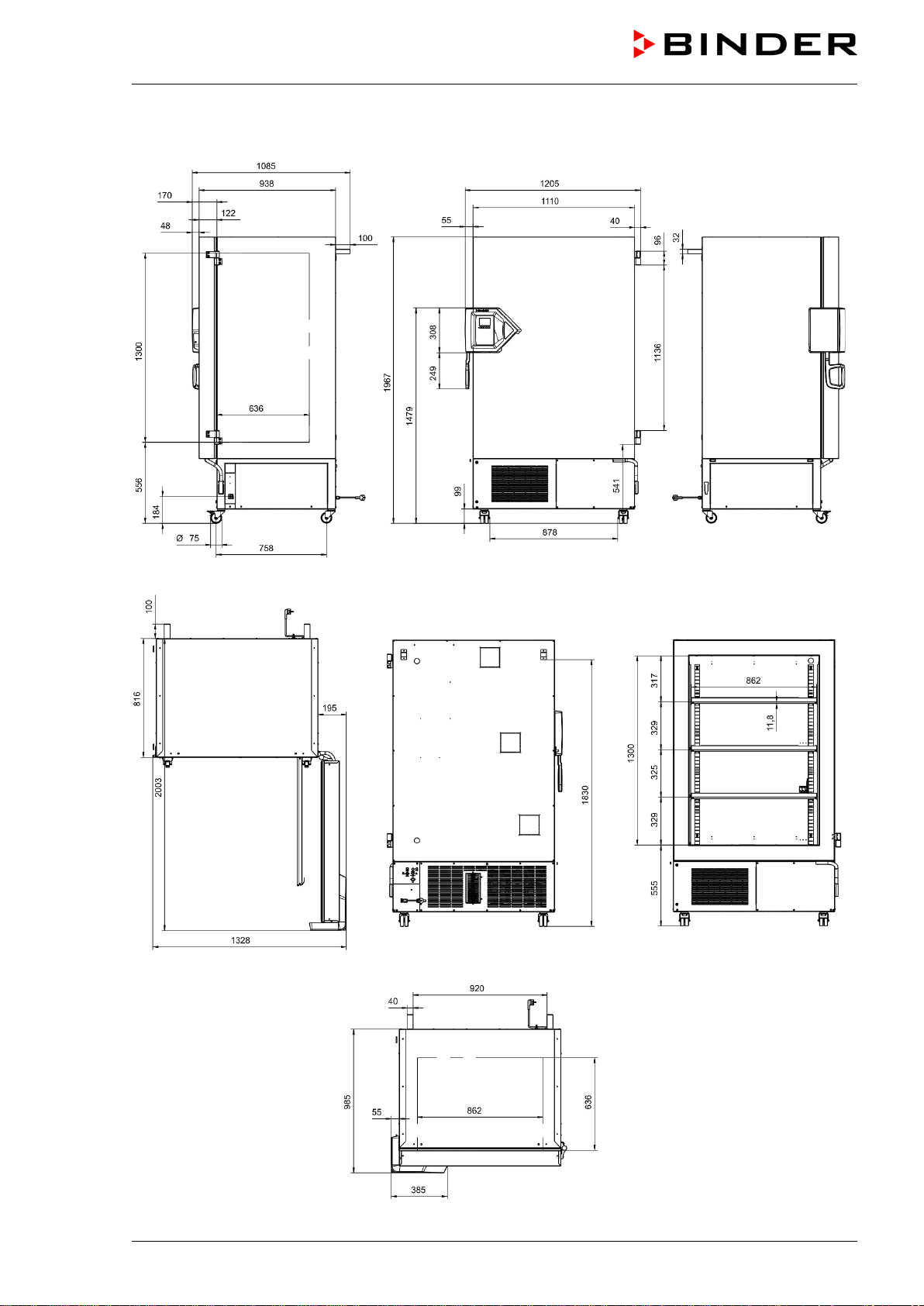
27.7
Dimensions
of
UF V
700
(E
3)
Dimens
ions
in mm
Loading ...
Loading ...
Loading ...
File type: PDF
File name: 63489177_uf-v-700.pdf
File size: 8.36 MB
File Language: English
Pages: 119
Author: Binder
File created: 2020-10-13
Published: 2021-08-19
Updated: 2023-05-22
Download File
Table of Contents
×
1. Safety
6
1.1 Personnel Qualification
6
1.2 Operating manual
6
1.3 Legal considerations
6
1.4 Structure of the safety instructions
7
1.4.1 Signal word panel
7
1.4.2 Safety alert symbol
7
1.4.3 Pictograms
8
1.4.4 Word message panel structure
8
1.5 Localization / position of safety labels at the chamber
9
1.6 Type plate
10
1.7 General safety instructions on installing and operating the chamber
11
1.8 Intended use
13
1.9 Foreseeable Misuse
14
1.10 Residual Risks
15
1.11 Operating instructions
16
1.12 Measures to prevent accidents
16
2. Chamber description
17
2.1 Chamber overview
19
2.2 Door lock and controller housing
21
2.2.1 Operating the NumPad (option âDoor access systemâ)
22
2.2.2 Operating the electromechanical door locking (option âDoor access systemâ)
22
2.3 Main power switch
23
2.4 Chamber rear
24
2.5 Doors
25
2.5.1 Outer door
25
2.5.2 Compartment doors
25
2.6 Drain well for condensate during defrosting (option)
26
3. Completeness of delivery, transportation, storage, and installation
27
3.1 Unpacking, and checking equipment and completeness of delivery
27
3.2 Guidelines for safe lifting and transportation
28
3.2.1 Moving the freezer inside a building
28
3.2.2 Transport outside a building
29
3.3 Storage
30
3.4 Location of installation and ambient conditions
30
4. Installation and connections
32
4.1 Operating instructions
32
4.2 Spacers for rear wall distance
32
4.3 Adjustable shelves
33
4.4 Connections of cooling water for chambers with water cooling
35
4.4.1 Connection of cooling water outlet for water cooling
35
4.4.2 Connection of cooling water inlet for water cooling
36
4.4.3 Connection kit for cooling water
36
4.5 Electrical connection
38
4.6 Advanced voltage booster (option)
38
5. Functional overview of the RD4 chamber controller
39
5.1 Menu structure of the controller and access levels
40
6. Start up
41
6.1 Preset factory parameters
41
6.2 Behavior after turning on the chamber
41
7. Temperature set-point entry
42
8. Placing samples in storage in the freezer
43
9. Setting special controller functions
44
10. Password
45
10.1 Password request
45
10.2 Assign and modify a password
45
10.2.1 Assign and modify the User password
46
10.2.2 Assign and modify the Admin password
46
10.3 Performance during and after power failure and shut down
47
11. Safety controller (temperature safety device)
47
11.1 Setting the safety controller mode
48
11.2 Setting the safety controller value
48
11.3 Message and measures in the state of alarm
49
11.4 Function check
49
12. General controller settings
50
12.1 Selecting the controllerâs menu language
50
12.2 Selecting the temperature unit
50
12.3 Setting the current date
51
12.4 Setting the current time
52
12.5 Function âLanguage selection at restartâ
52
12.6 Setting the chamber address
53
12.7 Display brightness
53
13. Tolerance range and alarm delay settings
54
13.1 Setting the delay time for door open alarm
54
13.2 Setting the delay time for tolerance range alarm
54
13.3 Setting the temperature tolerance range
55
14. Alarm functions
56
14.1 Alarm messages
56
14.2 Information messages
58
14.3 Activating / deactivating the audible alarm (alarm buzzer)
58
14.4 Required actions in case of an alarm
59
14.4.1 Safety controller temperature alarm
59
14.4.2 Temperature tolerance range alarm (too high and too low temperature)
59
14.4.3 Door open alarm
60
14.4.4 Power failure alarm (chamber with option âbattery-buffered alarm systemâ)
60
14.4.5 Messages on the battery management system (chamber with option âbattery-buffered alarm systemâ)
61
14.4.6 Messages referring to temperature sensor failure
62
14.4.7 Messages referring to CO2 emergency cooling (option CO2 emergency cooling)
63
14.5 Zero-voltage relay alarm output
64
15. Ethernet network settings
65
15.1 Showing the network settings
65
15.1.1 Showing the chamberâs MAC address
65
15.1.2 Showing the IP address
65
15.1.3 Showing the subnet mask
66
15.1.4 Showing the standard gateway
66
15.1.5 Showing the DNS server address
66
15.1.6 Showing the DNS chamber name
67
15.2 Changing the configuration of the network settings
67
15.2.1 Selecting the type of IP address assignment (automatic / manual)
68
15.2.2 Selecting the type of assignment of the DNS server address (automatic / manual)
68
15.2.3 Assigning the IP address
68
15.2.4 Setting the subnet mask
69
15.2.5 Setting the standard gateway
70
15.2.6 Assigning the DNS server address
70
16. Access codes (option âDoor access systemâ)
71
16.1 Assigning the access codes
71
16.2 Opening the chamber door with the access code
72
17. Data recorder
73
17.1 Recorded data
73
17.2 Storage capacity
73
17.3 Setting the storage rate for the âDL1â recorder data
74
17.4 Deleting the data recorder
74
18. USB-Menu: Data transfer via USB interface
75
18.1 Connecting the USB stick
75
18.2 Import function
75
18.3 Export functions
76
18.4 Ongoing data transfer
76
18.5 Error during data transmission
77
18.6 Removing the USB stick
77
19. Battery management system (option âbattery-buffered alarm systemâ)
77
19.1 Battery operation
77
19.2 Charging voltage
78
20. Setting and activating the service setpoint
78
20.1 Setting the service setpoint
78
20.2 Activating the service setpoint
79
21. CO2 emergency cooling (option)
80
21.1 Connecting and exchanging the pressurized CO2 cylinder
81
21.2 Operating the CO2 emergency cooling system
83
21.3 Settings on the chamber controller
84
21.3.1 Setting the CO2 emergency cooling temperature setpoint
84
21.3.2 Activating the CO2 emergency cooling
85
21.3.3 Test run of the CO2 emergency cooling
86
22. Data monitoring and recording
87
22.1 Ethernet interface
87
22.2 APT-COM⢠4 Multi Management Software (option)
87
22.3 Analog output for temperature (option)
87
22.4 Data logger kit (option)
87
23. Chamber inventory: Storage rack systems and cryo boxes (option)
88
23.1 Storage rack systems with or without cryo boxes
88
23.2 Cryo boxes
88
24. Cleaning and decontamination
89
24.1 Cleaning
89
24.2 Decontamination
91
25. Maintenance and service, service, troubleshooting, repair, testing
92
25.1 General information, personnel qualification
92
25.2 Maintenance work by the customer
93
25.2.1 Checking and cleaning / replacing the condenser air filter
93
25.2.2 Cleaning the condenser
94
25.2.3 De-icing and defrosting
94
25.2.4 Maintenance of the door lock
95
25.3 Simple troubleshooting
95
25.4 Maintenance intervals, service
98
25.5 Service Reminder
99
25.6 Sending the chamber back to BINDER GmbH
99
26. Disposal
100
26.1 Disposal of the transport packing
100
26.2 Decommissioning
100
26.3 Disposal of the chamber in the Federal Republic of Germany
100
26.4 Disposal of the chamber in the member states of the EU except for the Federal Republic of Germany
101
26.5 Disposal of the chamber in non-member states of the EU
103
27. Technical description
103
27.1 Factory calibration and adjustment
103
27.2 Over current protection
103
27.3 Technical data
103
27.4 Equipment and options (extract)
106
27.5 Optional equipment, accessories and spare parts (extract)
107
27.6 Dimensions of UF V 500 (E3)
109
27.7 Dimensions of UF V 700 (E3)
110
28. Certificates and declarations of conformity
111
28.1 EU Declaration of Conformity
111
29. Product registration
113
30. Contamination clearance certificate
114
30.1 For chambers located outside the USA and Canada
114
30.2 For chambers in the USA and Canada
117
Search:
×
Search