Loading ...
Loading ...
Loading ...
8
A
C
B
D
S3
S3
S2
S1
S2S1
21
F
CN105
RED
E
E
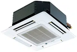
6.1.1. Indoor unit power supplied from outdoor unit (Fig. 6-2)
The following connection patterns are available.
The outdoor unit power supply patterns vary on models.
1 : 1 System
Indoor unit model SLZ-KA09 SLZ-KA12 SLZ-KA15
Power supply Single, 208/230V, 60Hz
Min. circuit ampacity 1 A
Fan motor (F.L.A) 0.23 A 0.28 A
Input capacity main switch/fuse 15 A
Wiring
Wire No. ×
size
Indoor unit - Outdoor unit *1 3 × AWG 14 (Polar)
Indoor unit - Outdoor unit earth 1 × Min. AWG 16
Wired remote controller - Indoor unit *2 2 × AWG 22 (Non-polar)
Circuit rat-
ing
Indoor unit - Outdoor unit S1-S2 *3 AC 208/230 V
Indoor unit - Outdoor unit S2-S3 *3 DC 24 V
Wired remote controller - Indoor unit *3 DC 12 V
*1 Max. 50 m, 165 ft
*2 The 10 m, 30 ft wire is attached in the wired remote controller accessory. Max. 500 m, 1500
ft.
*3 The fi gures are NOT always against the ground.
S3 terminal has DC24V against S2 terminal. However between S3 and S1, these terminals
are not electrically be the transformer or other device.
Note:
1. Wiring size must comply with the applicable local and national code.
2. Use copper supply wires.
3. Use wires rated 600V or more for the power supply cables and the indoor
unit/outdoor unit connecting cables.
4. Install an earth longer than other cables.
Caution:
• Use care not to make miswiring.
• Firmly tighten the terminal screws to prevent them from loosening.
• After tightening, pull the wires lightly to confi rm that they do not move.
Fig. 6-2
A
Indoor unit
B
Outdoor unit
C
Wired remote controller
D
Main switch/fuse
E
Grounding
F
Indoor controller board
For Power supply
6. Electrical work
6.2. Remote controller
6.2.1. Wired remote controller
1) 2 remote controllers setting
If 2 remote controllers are connected, set one to “Main” and the other to “Sub”. For
setting procedures, refer to “Function selection of remote controller” in the opera-
tion manual for the indoor unit.
Fig. 6-3
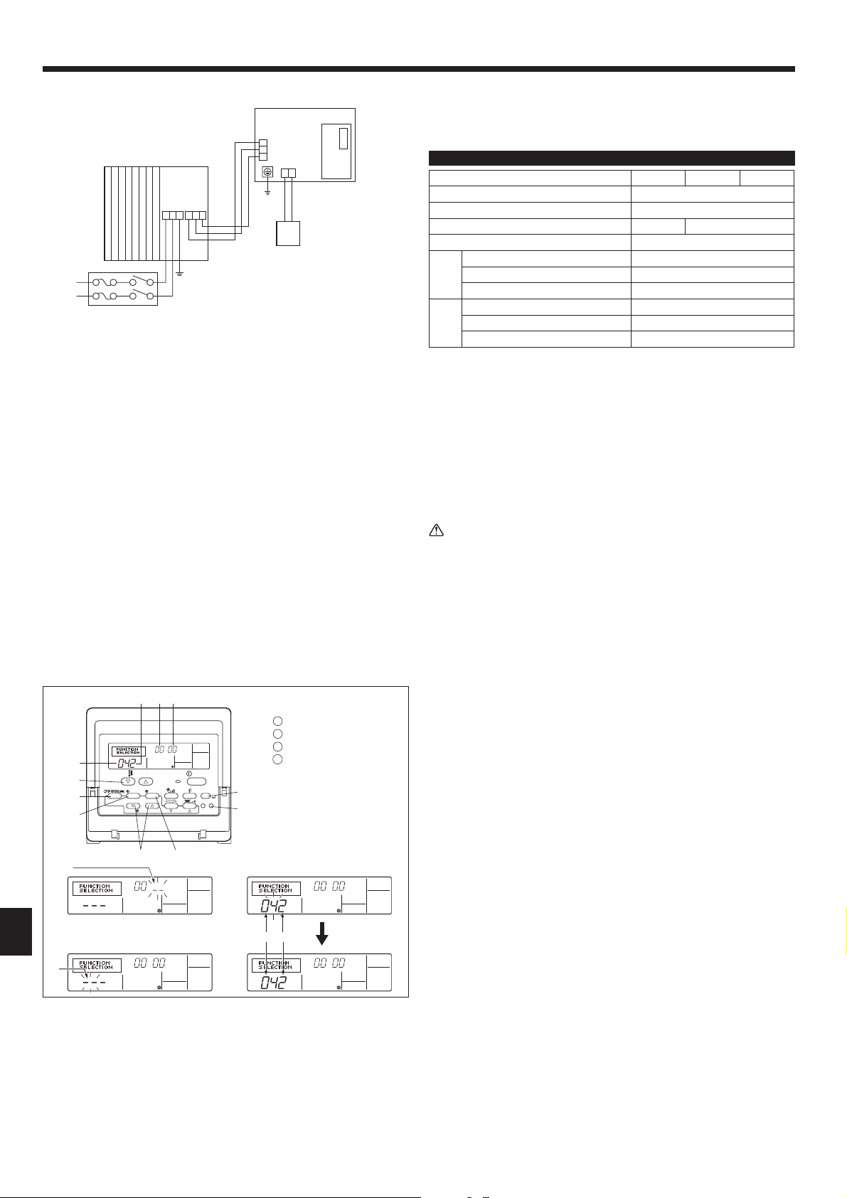
6.3. Function settings
For wired remote controller only (Fig. 6-3)
Changing the power voltage setting
• Be sure to change the power voltage setting depending on the voltage used.
1
Go to the function setting mode.
Switch OFF the wired remote controller.
Press the
A
and
B
buttons simultaneously and hold them for at least 2
seconds. FUNCTION will start to fl ash.
2
Use the
C
button to set the refrigerant address (
3
) to 00.
3
Press
D
and [--] will start to fl ash in the unit number (
4
) display.
4
Use the
C
button to set the unit number (
4
) to 00.
5
Press the
E
MODE button to designate the refrigerant address/unit number. [--]
will fl ash in the mode number (
1
) display momentarily.
6
Press the
F
buttons to set the mode number (
1
) to 04.
7
Press the
G
button and the current set setting number (
2
) will fl ash.
Use the
F
button to switch the setting number in response to the power supply
voltage to be used.
Power supply voltage
230 V : setting number = 1
208 V : setting number = 2
8
Press the MODE button
E
and mode and the setting number (
1
) and (
2
) will
change to being on constantly and the contents of the setting can be confi rmed.
9
Press the FILTER
A
and TEST RUN
B
buttons simultaneously for at least two
seconds. The function selection screen will disappear momentarily and the air
conditioner OFF display will appear.
PAR-21MAA
ON/OFF
FILTER
CHECK
OPERATION
CLEAR
TEST
TEMP.
MENU
BACK DAY
MONITOR/SET
CLOCK
ON/OFF
A
B
DC
G
E
F
4
1
2
1
3 4
12
1
Mode number
2
Setting number
3
Refrigerant address
4
Unit number
Loading ...
Loading ...
Loading ...