Loading ...
Loading ...
Loading ...
4
30
120
120
25/32
2-15/16
3-15/16
2-3/4
19/32
120
120
3-5/8
1
1-1/16
+3/16
0
8-3/16
3-15/
16
(22-11/16)
25-19/32
22-11/16 to 24-13/32
1-1/2 to 2-9/32
3-21/32
1-7/8
7-5/32
22-11/16 to 24-13/32
16-17/32
22-7/16
13-3/16
3-7/16
19/32 to 1-15/32
25-19/32
25/32
8-3/16
9-1/4 1/2
40
1-1/16
+3/16
0
20-7/8
13-3/16
22-7/16
Min.18
Min.18 6
13-27/32
7-27/32
19/32 to 1-15/32
19/32 to 1-15/32
(22-11/16)
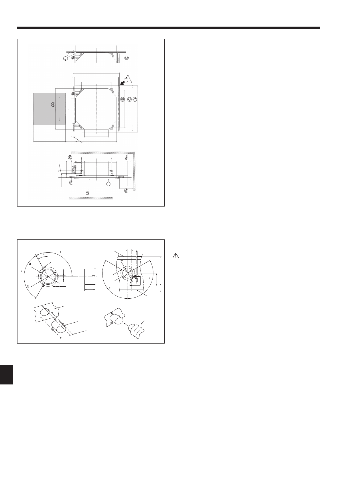
4.3. Installation of duct (in case of fresh air intake)
(Fig. 4-3)
Caution:
Linkage of duct fan and air conditioner
ln case that a duct fan is used, be sure to make it linked with the air condi-
tioner when outside air is taken.
Do not run the duct fan only. It can cause dew drop.
Making a duct fl ange (prepared locally)
• The shape of duct fl ange shown left is recommended.
Installation of duct fl ange
• Cut out the cutout hole. Do not knock it out.
• Install a duct fl ange to the cutout hole of the indoor unit with three 4 × 10 mm, 4 ×
1/2 inch tapping screws which should be prepared locally.
Installation of duct (should be prepared locally)
• Prepare a duct of which inner diameter fi ts into the outer diameter of the duct
fl ange.
• In case that the environment above the ceiling is high temperature and high hu-
midity, wrap the duct in a heat insulate to avoid causing dew drop on the wall.
A
Duct fl ange recommended shape
F
3-ø2.8 mm, ø1/8 inch Burring hole
(Thickness: 0.8 mm, 1/32 inch or more)
G
ø73.4 mm, ø2-7/8 inch cutout hole
B
3-ø5 mm, ø3/16 inch hole
H
Duct fl ange (Prepared locally)
C
Detail drawing of fresh air intake
I
4 × 10 mm,
ø
4 × 1/2 inch Tapping screw
(Prepared locally)
D
Indoor unit
E
Ceiling surface
J
Duct
Fig. 4-3
A
(inch)
C
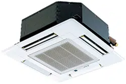
4.2. Ceiling openings and suspension bolt installation
locations (Fig. 4-2)
• Using the installation template (top of the package) and the gauge (supplied as
an accessory with the grille), make an opening in the ceiling so that the main unit
can be installed as shown in the diagram. (The method for using the template
and the gauge are shown.)
* Before using, check the dimensions of template and gauge, because they
change due to fl uctuations of temperature and humidity.
* The dimensions of ceiling opening can be regulated within the range shown
in following diagram; so center the main unit against the opening of ceiling,
ensuring that the respective opposite sides on all sides of the clearance be-
tween them becomes identical.
• Use M10 (3/8") suspension bolts.
* Suspension bolts are to be procured at the fi eld.
• Install securely, ensuring that there is no clearance between the ceiling panel &
grille, and between the main unit & grille.
A
Outer side of main unit
G
Min. 500 mm, 20 inch (Entire periphery)
B
Bolt pitch
If setting the maintenance space for
G
, be sure to
leave is a minimum of 700 mm, 28 inch.
C
Ceiling opening
D
Outer side of Grille
H
Maintenance space
E
Grille
I
Fresh air intake
F
Ceiling
J
Angle
K
Electric component box
* Note that the space between ceiling panel of the unit and ceiling slab, etc., must
be 10 to 15 mm, 3/8 to 9/16 inch to be left.
* Leave the maintenance space at the electric component box end.
Fig. 4-2
(inch)
4. Installing the indoor unit
Loading ...
Loading ...
Loading ...