Loading ...
Loading ...
Loading ...
6
2-1/4
1-7/32
2-7/32
4-3/4 2-19/32
7-15/16 9-1/16
7-19/32
21/32
45° ± 2°
R1/64 to R1/32
øA
90° ± 0.5°
,
5. Refrigerant pipe and drain pipe
Fig. 5-1
Fig. 5-2
Fig. 5-3
Fig. 5-4
A
As viewed from A
(inch)
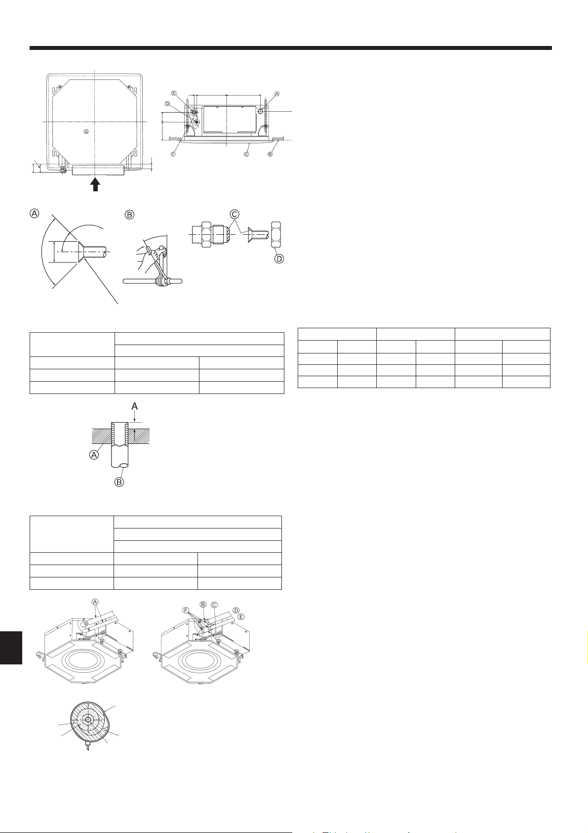
5.1. Refrigerant and drainage piping locations of indoor
unit (Fig. 5-1)
A Drain pipe
B Ceiling
C Grille
D Refrigerant pipe (liquid)
E Refrigerant pipe (gas)
F Water supply inlet
G Main unit
5.2. Connecting pipes (Fig. 5-2)
• When commercially available copper pipes are used, wrap liquid and gas pipes
with commercially available insulation materials (heat-resistant to 100°C, 212°F or
more, thickness of 12 mm, 1/2 inch or more).
• The indoor parts of the drain pipe should be wrapped with polyethylene foam insula-
tion materials (specifi c gravity of 0.03, thickness of 9 mm, 23/64 inch or more).
• Apply thin layer of refrigerant oil to pipe and joint seating surface before tightening
fl are nut.
• Use 2 wrenches to tighten piping connections.
• Use refrigerant piping insulation provided to insulate indoor unit connections. Insulate
carefully.
B Flare nut tightening torque
Copper pipe O.D. Flare nut O.D. Tightening torque
mm inch mm inch N·m ft - lbs
6.35 1/4 17 43/64 13.7 to 17.7 10 to 13
9.52 3/8 22 7/8 34.3 to 41.2 25 to 30
12.7 1/2 26
1-1/32
49.0 to 56.4 36 to 42
C
Do not apply refrigerating machine oil to the screw portions.
(This will make the fl are nuts more apt to loosen.)
D
Be certain to use the fl are nuts that are attached to the main unit.
(Use of commercially-available products may result in cracking.)
E
Apply refrigerating machine oil over the entire fl are seat surface.
5.3. Indoor unit (Fig. 5-4)
Heat insulation for refrigerant pipes:
1 Wrap the enclosed large-sized pipe cover around the gas pipe, making sure that
the end of the pipe cover touches the side of the unit.
2 Wrap the enclosed small-sized pipe cover around the liquid pipe, making sure that
the end of the pipe cover touches the side of the unit.
3 Secure both ends of each pipe cover with the enclosed bands. (Attach the bands
20 mm, 25/32 inch from the ends of the pipe cover.)
• After connecting the refrigerant piping to the indoor unit, be sure to test the pipe
connections for gas leakage with nitrogen gas. (Check that there is no refrigerant
leakage from the refrigerant piping to the indoor unit.)
A Flare cutting dimensions
Copper pipe O.D.
(mm, inch)
Flare dimensions
øA dimensions (mm, inch)
ø6.35, 1/4” 8.7 to 9.1 11/32 to 23/64
ø9.52, 3/8” 12.8 to 13.2 1/2 to 33/64
ø12.7, 1/2” 16.2 to 16.6 41/64 to 21/32
A Die
B Copper pipe
Copper pipe O.D.
(mm, inch)
A
Flare tool for R410A
Clutch type (mm, inch)
ø6.35, 1/4” 0 to 0.5 0 to 1/64
ø9.52, 3/8” 0 to 0.5 0 to 1/64
ø12.7, 1/2” 0 to 0.5 0 to 1/64
A
Refrigerant pipe and insulating material
(Procure locally)
B
Pipe cover (large) (Accessory)
C
Pipe cover (small) (Accessory)
D
Refrigerant pipe (gas)
E
Refrigerant pipe (liquid)
F
Band (Accessory)
G
Cross-sectional view of connection
H
Refrigerant pipe
I
Insulating material
J
Squeeze
Loading ...
Loading ...
Loading ...