Loading ...
Loading ...
Loading ...
13
Fig. 8-1
8. Test run
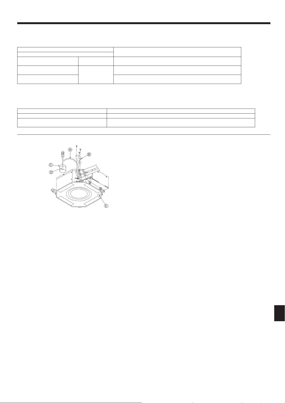
8.4. Check drainage
(Fig. 8-1)
• During the test run, ensure the water is being properly drained out and that no
water is leaking from joints.
• Always check this during installation even if the unit is not required to provide
cooling/drying at that time.
• Similarly, check the drainage before fi nishing ceiling installation in a new premis-
es.
(1) Remove the cover of the water supply inlet and add about 1000 cc, 1/4 gal of
water using a water supply pump etc. During this process, be careful not to
spray water into the drain pump mechanism.
(2) Confi rm that water is being drained out through the drainage outlet, after switch-
ing over from remote control mode to test run mode (cooling mode).
(3) After checking the drainage, ensure that the cover is replaced and the power
supply is isolated.
(4) After confi rming the drainage system is functioning, replace the drain plug.
A
Insert the pump end 3 to 5 cm, 1-3/16 to 2 inch
D
Water
B
Cover of water supply inlet
E
Drain plug
C
About 1000 cc, 1/4 gal
• On wired remote controller
Check code displayed in the LCD.
• If the unit cannot be operated properly after the above test run has been performed, refer to the following table to remove the cause.
Note:
Operation is not possible for about 30 seconds after cancellation of function selection. (Correct operation)
For description of each LED (LED1, 2, 3) provided on the indoor controller, refer to the following table.
LED1 (power for microcomputer) Indicates whether control power is supplied. Make sure that this LED is always lit.
LED2 (power for wired remote controller) Indicates whether power is supplied to the wired remote controller.
LED3 (communication between indoor and outdoor units)
Indicates state of communication between the indoor and outdoor units. Make sure that this LED
is always blinking.
Symptom
Cause
Wired remote controller/ RF thermostat
PLEASE WAIT
For about 2 minutes
following power-on
• For about 2 minutes following power-on, operation of the remote controller is not
possible due to system start-up. (Correct operation)
PLEASE WAIT → Error code
After about 2 minutes
has expired following
power-on
• Connector for the outdoor unit’s protection device is not connected.
• Reverse or open phase wiring for the outdoor unit’s power terminal block
Display messages do not appear even
when operation switch is turned ON
• Incorrect wiring between indoor and outdoor units (incorrect polarity of S1, S2, S3)
• Remote controller wire short
Loading ...
Loading ...
Loading ...