Loading ...
Loading ...
Loading ...
5
1-1/16
3-21/32
+3/16
0
Min. 1-3/16
Min. 22-11/16
Max. 24-13/32
A=1-1/16
+3/16
0
*B
*B
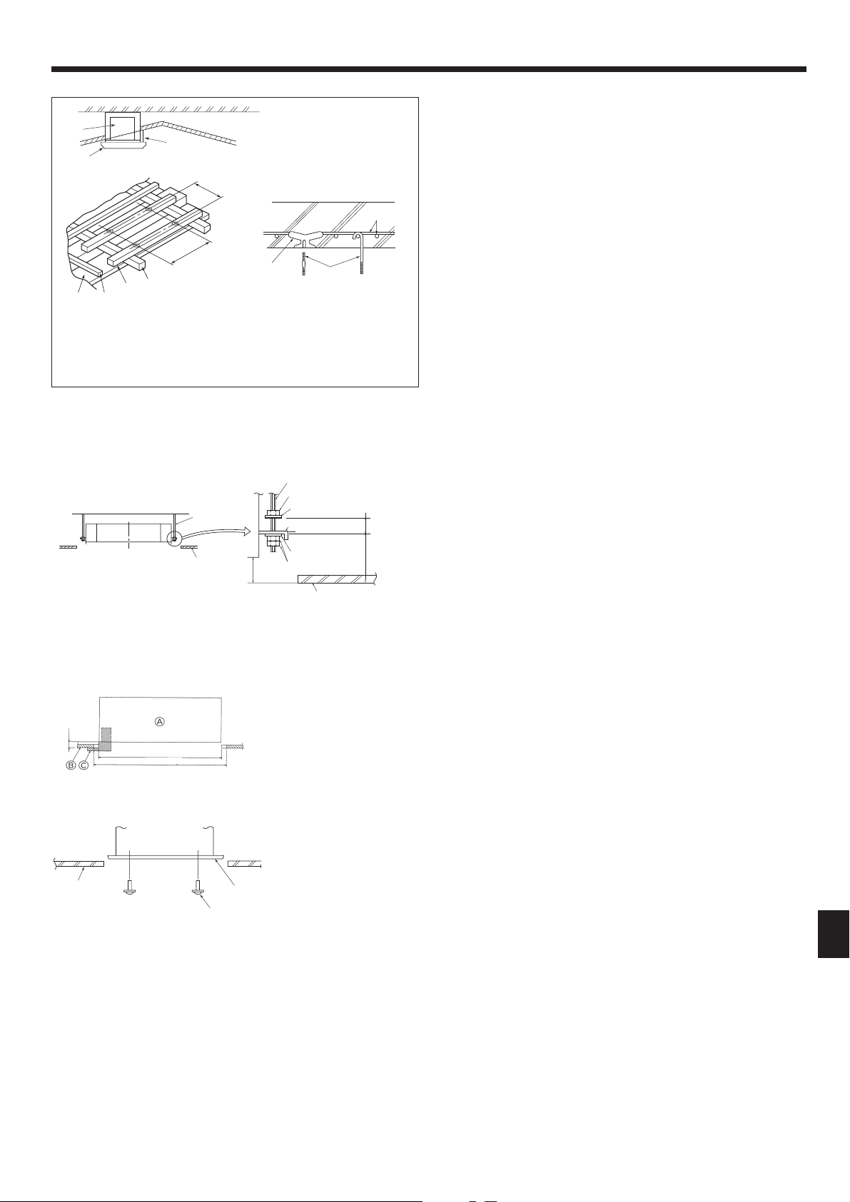
4. Installing the indoor unit
4.4. Suspension structure (Give site of suspension
strong structure) (Fig. 4-4)
• The ceiling work differs according to the construction of the building. Building
constructors and interior decorators should be consulted for details.
(1) Extent of ceiling removal: The ceiling must be kept completely horizontal and
the ceiling foundation (framework: wooden slats and slat holders) must be rein-
forced in order to protect the ceiling from vibration.
(2) Cut and remove the ceiling foundation.
(3) Reinforce the ends of the ceiling foundation where it has been cut and add ceil-
ing foundation for securing the ends of the ceiling board.
(4) When installing the unit on a slanting ceiling, interlock a pillow between the ceil-
ing and the grille and set so that the unit is installed horizontally.
1
Wooden structures
• Use tie beams (single-story houses) or second fl oor beams (two story houses) as
reinforcing members.
•
Wooden beams for suspending air conditioners must be sturdy and their sides
must be at least 6 cm, 2-3/8 inch long if the beams are separated by not more than
90 cm, 35-7/16 inch and their sides must be at least 9 cm, 3-9/16 inch long if the
beams are separated by as much as 180 cm, 70-7/18 inch. The size of the suspen-
sion bolts should be ø10 mm, 3/8 inch. (The bolts do not come with the unit.)
2
Ferroconcrete structures
Secure the suspension bolts using the method shown, or use steel or wooden
hangers, etc. to install the suspension bolts.
A
Unit
B
Grille
C
Pillow
D
Ceiling
E
Rafter
F
Beam
G
Roof beam
H
Use inserts rated at 100-150 kg, 250-350 lbs
each (procure locally)
I
Suspension bolts M10 (3/8") (procure locally)
J
Steel reinforcing rod
1
2
Fig. 4-4
A
Suspension bolt (Procure locally)
B
Ceiling
C
Nut (Procure locally)
D
Washer (with insulation) (Accessory)
Fig. 4-5
A
Main unit
B
Ceiling
C
Installation template (Accessory)
D
Screw with washer (Accessory)
Fig. 4-7
Fig. 4-6
*B: Suspension bolt pitch (see Fig. 4-2
B
for details)
E
Mounting plate
F
Washer (without insulation) (Accessory)
G
Check using the Installation gauge
A
Main unit
B
Ceiling
C
Gauge (Grille accessory)
D
Ceiling opening dimensions
(inch)
4.5. Unit suspension procedures (Fig. 4-5)
Suspend the main unit as shown in the diagram.
1. In advance, set the parts onto the suspension bolts in the order of the washers
(with insulation), washers (without insulation) and nuts (double).
• Fit the washer with cushion so that the insulation faces downward.
• In case of using upper washers to suspend the main unit, the lower washers (with
insulation) and nuts (double) are to be set later.
2. Lift the unit to the proper height of the suspension bolts to insert the mounting
plate between washers and then fasten it securely.
3. When the main unit can not be aligned against the mounting hole on the ceiling,
it is adjustable owing to a slot provided on the mounting plate. (Fig. 4-6)
• Make sure that step A is performed within 27 mm, 1-1/16 inch. Damage
could result by failing to adhere to this range.
4.6. Confi rming the position of main unit and tighten-
ing the suspension bolts (Fig. 4-7)
• Using the gauge attached to the grille, ensure that the bottom of the main unit is
properly aligned with the opening of the ceiling. Be sure to confi rm this, otherwise
condensation may form and drip due to air leakage etc.
• Confi rm that the main unit is horizontally levelled, using a level or a vinyl tube
fi lled with water.
• After checking the position of the main unit, tighten the nuts of the suspension
bolts securely to fasten the main unit.
• The installation template can be used as a protective sheet to prevent dust from
entering the main unit when the grilles are left unattached for a while or when the
ceiling materials are to be lined after installation of the unit is fi nished.
*
As for the details of fi tting, refer to the instructions given on the Installation template.
+5
0
+3/16
0
Loading ...
Loading ...
Loading ...