Loading ...
Loading ...
Loading ...
11
A
Fig. 7-8
7.4. Locking the up/down airfl ow direction (Fig. 7-9)
The vanes of the unit can be set and locked in on up or down orientation depending
upon the environment of use.
• Set according to the preference of the customer.
The operation of the fixed up/down vanes and all automatic controls cannot
be performed using the remote controller. In addition, the actual position of the
vanes may differ from the position indicated on the wired remote controller.
1
Turn off the main power switch.
Injuries and or an electrical shock may occur while the fan of the unit is rotating.
2
Disconnect the connector for the vane motor of the vent that you want to lock.
(While pressing the button, remove the connector in the direction indicated by
the arrow as shown in the diagram.) After removing the connector, insulate it
with tape.
3
To adjust the desired airfl ow direction, slowly move the up/down vanes within
the specifi ed range. (Fig. 7-10)
Specifi ed range
Up/down airfl ow
direction
Horizontal 30°
Downward 45° Downward 55° Downward 70°
A
21 mm
13/16 inch
25 mm
31/32 inch
28 mm
1-3/32 inch
30 mm
1-3/16 inch
• The vanes can be set between 21 and 30 mm (13/16 and 1-3/16 inch).
Caution:
Do not set the up/down vanes passed the specified range. Condensation
could form on and drop from the ceiling, or the unit could malfunction.
Fig. 7-9
A
Button
B
Vane motor
C
Up/down vanes
D
Connector
Fig. 7-10
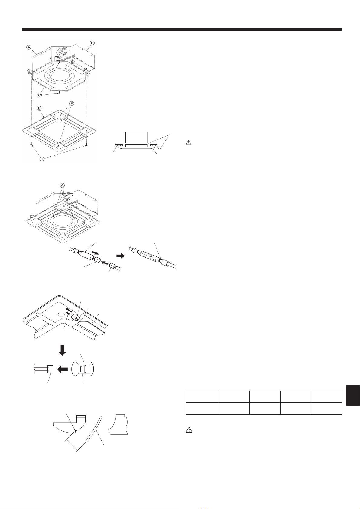
7.3.4. Wire connection (Fig. 7-8)
• Be sure to connect the unit to the connector (white: 10-pole/red: 9-pole). Next,
attach the white glass tube that comes with the main unit so that the tube covers
the connector. Close the opening of the glass tube with the band.
• Make sure that there is no slack in the each lead wire at the fastener on the grille.
A
Fastener (Accessory)
B
White glass tube
C
Connector of the main unit
D
Connector of the grille
E
Band (Accessory)
E
Measurement standard
position of grille
F
Up/down vanes
7. Installing the grille
7.3.2. Temporary installation of the grille (Fig. 7-6)
• Align the electric component box of the main unit and the receiver of the grille,
and then temporarily secure the grille using the bell shaped holes.
* Make sure that the lead wiring of the grille does not get pinched between the
grille and the main unit.
A
Main unit
B
Electric component box
C
Screw with washer (for temporary use)
D
Screw with washer (Accessory)
E
Grille
F
Bell shaped hole
7.3.3. Securing the grille (Fig. 7-7)
• Secure the grille to the main unit by tightening the previously installed 2 screws
(with captive washer) as well as the 2 remaining screws (with captive washer).
* Make sure that there are no gaps between the main unit and the grille or the
grille and the ceiling.
Caution:
When tightening the screw with captive washer
2
, tighten it at a torque of
4.8 N·m (3.5 ft·lbs) or less. Never use an impact screwdriver.
•
It may result in parts damage.
A
Ceiling
B
Main unit
C
Grille
D
Make sure that there are no gaps.
Fig. 7-6
Fig. 7-7
Loading ...
Loading ...
Loading ...