Loading ...
Loading ...
Loading ...
7
Max. 65ft.
5 to 7 ft
Max. 6 in.
7/16
1-3/16 1-3/16 1-3/16
,
A
C
G
D
H
E
B
F
CN105
RED
E
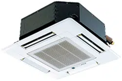
5. Refrigerant pipe and drain pipe
Fig. 5-5
5.4. Drainage piping work (Fig. 5-5)
• Use VP25 (O. D. ø32 mm, 1-1/4 inch PVC TUBE) for drain piping and provide
1/100 or more downward slope.
• Be sure to connect the piping joints using a polyvinyl type adhesive.
• Observe the fi gure for piping work.
• Use the included drain hose to change the extraction direction.
1
Correct piping
C
Support metal
2
Wrong piping
K
Air bleeder
A
Insulation (9 mm, 3/8 inch or more)
L
Raised
B
Downward slope (1/100 or more)
M
Odor trap
Grouped piping
D
O. D. ø32 mm, 1-1/4 inch PVC TUBE
E
Make it as large as possible
F
Indoor unit
G
Make the piping size large for grouped piping.
H
Downward slope (1/100 or more)
I
O. D. ø38 mm, 1-1/2 inch PVC TUBE for grouped piping.
(9 mm, 3/8 inch or more insulation)
J
Up to 500 mm, 19-11/16 inch
1
2
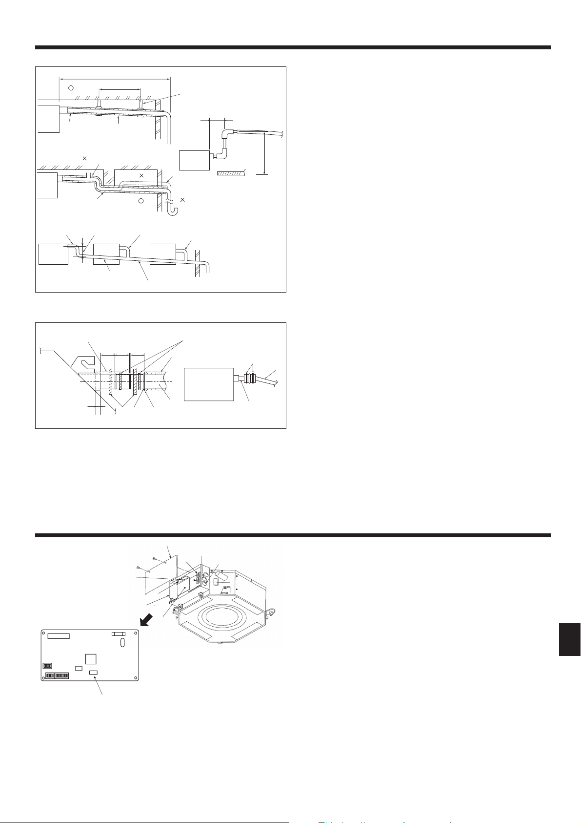
6. Electrical work
6.1. Indoor unit (Fig. 6-1)
1. Remove 2 screws to detach the electric component cover.
2. Route each cable through the wiring intake into the electric component box.
(Procure power supply cable and control cable locally.)
3. Securely connect the power supply cable and control cable to the terminal
blocks.
4. Secure the cables with clamps outside the electric component box.
5. Attach the electric component cover as it was.
• Do not allow slackening of the terminal screws.
• Always install earth.
(Earth cable dia: Thicker than 1.6 mm, 5/8 inch (AWG14))
• Fix power supply cable and control cable to electric component box by using
buffer bushing for tensile force. (PG connection or the like.)
• Tape is affi xed over the conduit hole used for connecting the electric wiring.
Please remove this tape if making a connection through the hole.
Fig. 6-1
(inch)
Fig. 5-6
1. Connect the drain socket (supplied with the unit) to the drain port. (Fig. 5-6)
(Affi x the tube using PVC adhesive then secure it with a band.)
2. Install a locally purchased drain pipe (PVC pipe, O.D. ø32 mm, 1-1/4 inch).
(Affi x the pipe using PVC adhesive then secure it with a band.)
3. Insulate the tube and pipe. (PVC pipe, O.D. ø32 mm, 1-1/4 inch and socket)
4. Check that drain fl ows smoothly.
5. Insulate the drain port with insulating material, then secure the material with a
band. (Both insulating material and band are supplied with the unit.)
A
Main unit
G
Drain pipe (O.D. ø32 mm, 1-1/4 inch PVC TUBE)
B
Insulating material
H
Insulating material (purchased locally)
C
Band (large)
I
Transparent PVC pipe
D
Drain port (transparent)
J
O.D. ø32 mm, 1-1/4 inch PVC TUBE
(Slope 1/100 or more)
E
Insertion margin
K
Band (small)
F
Matching
L
Drain socket
A
Electric component cover
E
Indoor controller board
B
Electric component box
F
Power board
C
Indoor/outdoor unit connecting terminal
G
Indoor - outdoor connecting cable of Location
D
Wired remote controller terminal
H
Remote control cable of Location
Loading ...
Loading ...
Loading ...