Loading ...
Loading ...
Loading ...
10
1
23
45
A=1-1/16
Min.22-11/16
Min.24-13/32
+3/16
0
19/32
to
25/32
Fig. 7-3
Fig. 7-4
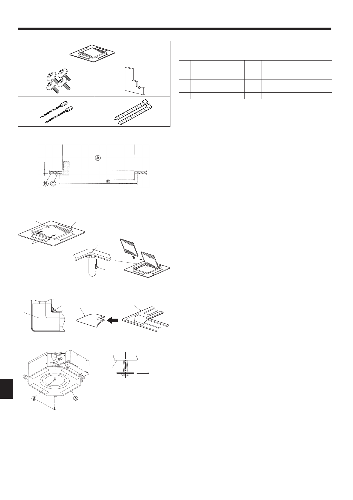
7.2. Preparing to attach the grille (Fig. 7-2)
• With the gauge supplied with this kit, adjust and check the positioning of the unit
relative to the ceiling. If the unit is not properly positioned in the ceiling, there
may be air leaks, condensation may form, or the up/down vanes may not operate
correctly.
• Make sure that the opening in the ceiling is within the following tolerances:
576 × 576 - 620 × 620 mm, 22-11/16 × 22-11/16 inch to 24-13/32 × 24-13/32 inch.
• Make sure that step A is performed within 27-32 mm, 1-1/16 to 1-1/4 inch. Dam-
age could result by failing to adhere to this range.
A
Main unit
B
Ceiling
C
Gauge (Accessory)
D
Ceiling opening dimensions
7.2.1. Removing the intake grille (Fig. 7-3)
• Slide the levers in the direction indicated by the arrow
1
to open the intake grille.
• Unlatch the hook that secures the grille.
* Do not unlatch the hook for the intake grille.
• With the intake grille in the “open” position, remove the hinge of the intake grille
from the grille as indicated by the arrow
2
.
Fig. 7-2
7.3. Installing the grille
• Please pay attention because there is a restriction in the attachment position of
the grille.
7.3.1. Preparations (Fig. 7-5)
• Install the 2 enclosed screws with washer in the main unit (at the corner refriger-
ant pipe area and at the opposite corner) as shown in the diagram.
A
Main unit
B
Detailed diagram of installed screw with washer (accessory).
(inch)
Fig. 7-5
7.2.2. Removing the corner panel (Fig. 7-4)
• Remove the screw from the corner of the corner panel. Slide the corner panel as
indicated by the arrow
1
to remove the corner panel.
A
Intake grille
E
Hole for the grille’s hook
B
Grille
F
Corner panel
C
Intake grille levers
G
Screw
D
Grille hook
7.1. Check the grille accessories (Fig. 7-1)
• The grille should be supplied with the following accessories.
Accessory name Q’ty Remark (mm, inch)
1
Grille 1 650 × 650 , 25-19/32 × 25-19/32
2
Screw with washer 4 M5 × 0.8 × 25, M5 × 1/32 × 31/32
3
Gauge 1
4
Fastener 2
5
Band 2
7. Installing the grille
Fig. 7-1
(inch)
Loading ...
Loading ...
Loading ...