Loading ...
Loading ...
Loading ...
En-6
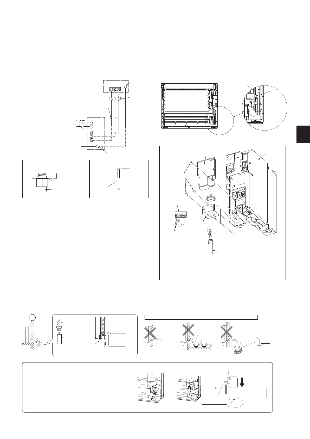
• Makeearthwirealittlelongerthanothers.(Morethan45mm)
• Forfutureservicing,giveextralengthtotheconnectingwires.
• Donotfoldtheexcesswire,orcramitintosmallspace.Takecautionnottodamagethe
wires.
• Besuretoattacheachscrewtoitscorrespondentterminalwhensecuringthecordand/
orthewiretotheterminalblock.
INDOOR UNIT
Terminalblock
208/230VAC
1phase,60Hz
Grounding
terminal**
Disconnect
switch*
OUTDOOR UNIT
Groundingterminal**
Ground
Powersupply
208/230VAC,
1phase2wires.
60Hz
Terminal
block1
Remark:
* Adisconnectswitch(15A
MAX)shouldberequired.
Checkthelocalcode.
** Usearingtongueterminal
inordertoconnectaground
wiretoterminal.
Terminalblock2
2-6. CONNECTING WIRES FOR INDOOR UNIT
Note: Whentheindoorunitispoweredfromtheoutdoorunit,dependingonlocalcode,adisconnectswitchneedstobeinstalledtoapowersupplycircuit.
1)Removetheelectricalcover.
2)Removetheconduitplate.
3)Attachtheconduitpipetotheconduitplatewiththelocknut.Theindoor/outdoorunitconnectingwire(A)appearingfromtheinsideofconduitpipeshouldbe
lessthan7/8in.(23mm).(Fig.1)
4)Processtheendofgroundwire(Fig.2).Connectittothegroundterminaloftheelectricalpartsbox.
5)Processtheendofindoor/outdoorunitconnectingwire(A)(Fig.2).Attachittotheterminalblock.Becarefulnottomakemis-wiring.Attachthewiretotheterminal
blocksecurelysothatitscorecannotbeseen,andnoexternalforceaffectstheconnectingsectionoftheterminalblock.
6)Firmlytightentheterminalscrews.Aftertightening,verifythatthewiresaretightlyfastened.
7)Reinstalltheconduitplate.
8)Reinstalltheelectricalcover.
Fig.1
Lead
wire
19/32in.
(15mm)
Fig.2
Terminalblock
Locknut
Electricalcover
Electricalbox
Conduitpipe
Grounding
terminal
Screw
Lessthan7/8in.
(23mm)
Conduitplate
Conduitpipe
Locknut
Conduitplate
Donotmakedrainpipingasshownbelow.
Accumulated
drainwater
Air
Waving
Water
leakage
Donotraise
Water
leakage
Water
leakage
Tipofdrain
hosedipped
inwater
Ditch
Atleast
1-31/32in.
(50mm)gap
Downward
slope
Drain
hose
SofthoseI.D.
19/32in.
(15mm)
Drainhose
Hardvinylchloride
pipeI.D.1-3/16in.
(30mm)
Insert
securely
Differentdiameterjoint
27-9/16in.
(70cm)or
more
Fig.1 Fig.2 Fig.3
2-7. DRAIN PIPING
• Iftheextensiondrainhosehastopassthrougharoom,besuretowrapitwithcommerciallysoldinsulation.
• Thedrainhoseshouldpointdownwardforeasydrainow.(Fig.1)
• Ifthedrainhoseprovidedwiththeindoorunitistooshort,connectitwithdrainhose(J)thatshouldbeprovidedatyoursite.(Fig.2)
• Whenconnectingthedrainhosetothehardvinylchloridepipe,besuretoinsertitsecurelyintothepipe.(Fig.3)
Fig.5
Projection
Makesureto
hookthecatch.
Drainhose
Pullthehoseto
conrmitiscon-
nectedsecurely.
Fig.4
The Drain hose is removed at installation.
• Whenroutingthedrainpiping,makesurethatthedrainhose
(1)isroutedasshown.(Fig.4)
• Insertthedrainhoseallthewaytothebaseofthedrain
pan(endconnection).(Fig.5)
Makesurethatthecatchofthedrainhoseissecurely
hookedontotheprojectiononthehosettingofthedrain
pan.
• Afterconnectingthedrainhose,besuretopullthehoseto
conrmthatitisconnectedsecurely.
Conduitpipe
Pipe
cover
JG79Y071H02_en.indd 6 2016/01/21 13:20:05
Loading ...
Loading ...
Loading ...