Loading ...
Loading ...
Loading ...
Piping
Liebert
®
SRC
™
86launaM resU
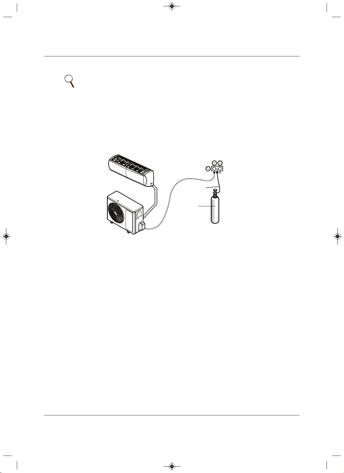
5.5.1.1 Connecting the pressure gauge
1. Connect the manifold valve (which includes the pressure gages) and the dry-nitrogen gas cylinder to
the services valves using a charge hose, Figure 5-41.
2. Pressurize the system to maximum 550 psig with dry-nitrogen gas and close the cylinder valve when
the gauge reaches 550 psig.
Figure 5-41 Leak-test set-up diagram
5.5.1.2 Soap-and-Water Leak Testing
1. Remove the caps from the 2-way and 3-way valves, Figure 5-39.
2. Open the 2-way valve by turning the valve stem counter-clockwise approximately 90 degrees, wait for
2 to 3 seconds, and close it.
3. While running nitrogen pressure, apply a soapy-water or liquid, neutral detergent on the indoor or
outdoor unit connections using a soft brush, and observe the connections for any leaks.
• Bubbles at connection points or joints indicate a leak.
4. Make a note of any leaks along the liquid and gas piping.
5. Disengage the nitrogen pressure by loosening the charge hose at the cylinder, Figure 5-41.
6. When pressure returns to normal, disconnect the charge hose from the cylinder.
7. Make repairs to all connections and piping where leaks were observed.
8. When repairs are complete, repeat the leak test using nitrogen pressure and check for further leaks.
9. Once the piping system is leak-free, proceed to 5.5.2 - Evacuation.
NOTE
• To avoid nitrogen entering the refrigerant system in a liquid state, the top of
the cylinder must be higher than its bottom when you pressurize the
system.
• Be sure the cylinder is used in a vertical standing position.
Lo Hi
Outdoor Unit
Manifold Valve
Charge Hose
Nitrogen Gas
Tank (Upright
Position)
Pressure
Gauge
Indoor Unit
Piping Bundle
MFL67502030 17. 7. 13. 오오 3:05 Page 78
Loading ...
Loading ...
Loading ...