Operator’s Manual
www.mechmaxx.com
WARRANTY

BEFORE USING THE MACHINE FOR THE FIRST TIME
Before using the machine for the first time, carry out the following.
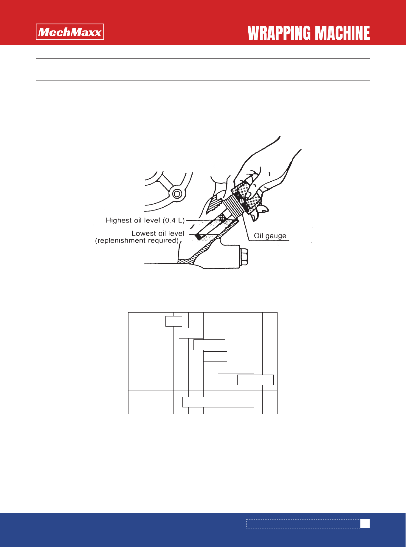
Check whether or not a specified quantity of engine oil exists. If it is too small, replenish the oil up filler port without
screwing it, and measure. Add oil up to the top graduation line of the oil gauge. The oil capacity is about 0.4 liter.
As the oil, use the engine oil for motor vehicles with a viscosity corresponding to the outside air temperature shown in
the following table.
• If the engine oil declines in quality or quantity, a trouble of seizure can be caused. Use the oil with quality of class SC
or higher.
• In the case where the outside air temperature is lower than-20°C or higher than 40°C, select the oil with a viscosity
and quality suitable for the local condition.
• Note that if an oil of multi grade is used, the oil consumption tends to increase when the outside air temperature is
high.
Oil Viscosity Selection Standard
1. CHECK THE ENGINE OIL.
PRECAUTION
1
www.mechmaxx.com
Single
grade
Multi
grade
-20 -10 0 10 20 30 40°C
10W-30
5W
10W
20W
#20
#30
#40
BEFORE USING THE MACHINE FOR THE FIRST TIME
2
www.mechmaxx.com
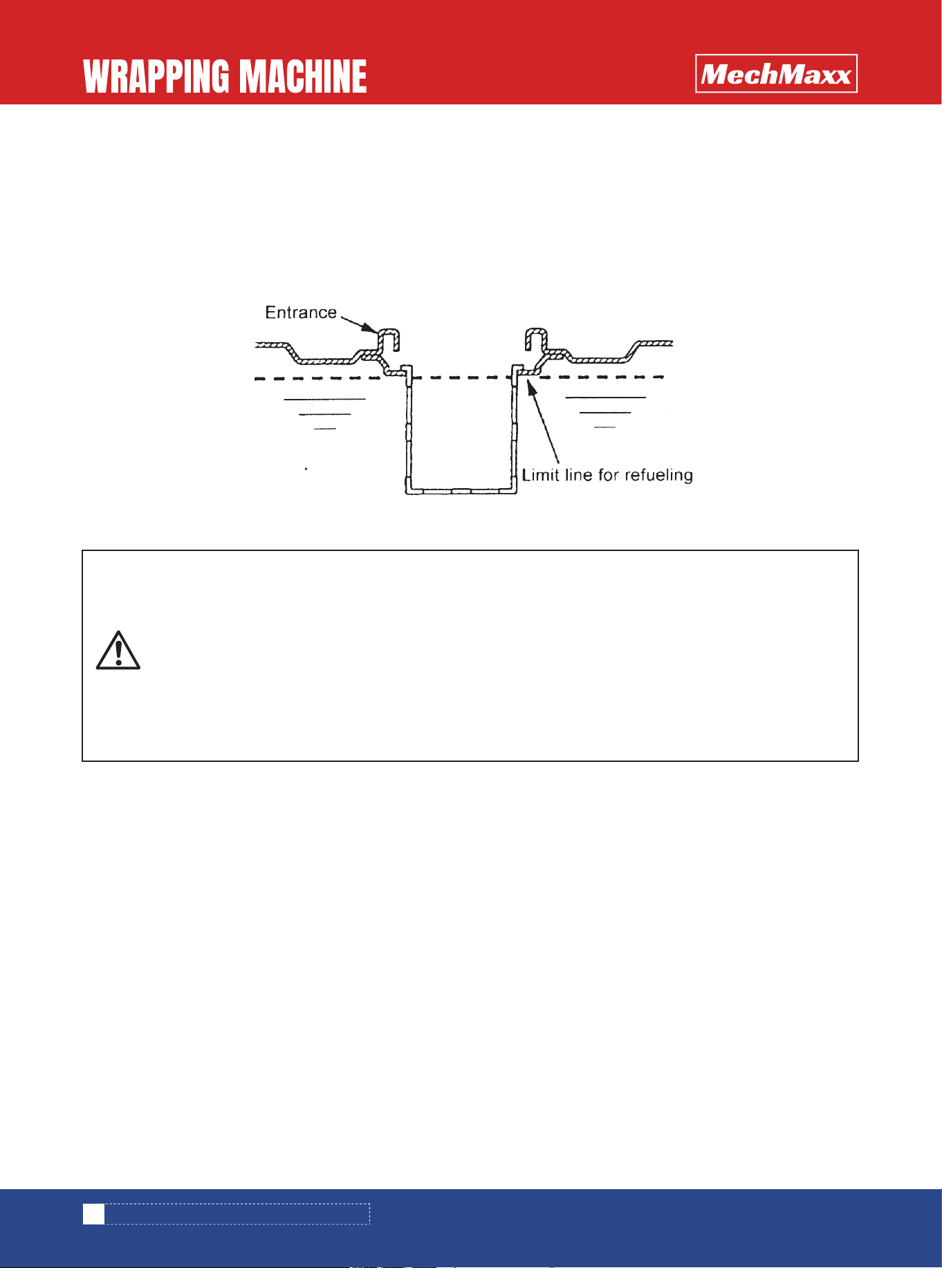
Use lead-free gasoline for motor vehicles as the fuel. The tank capacity is about 1.5 liters.
For refueling, do not fill up to the entrance of the fuel filler port, and keep the fuel level under the predetermined limit line
for refueling. If too much fuel is added, the fuel can bleed from the fuel tank cap dangerously.
For refueling, be sure to use the fuel filter screen installed in the fuel filler port.
2. CHECK THE QUANTITY OF FUEL.
PRECAUTION
• If fire is brought close to the fuel filler port, a fire may break out. Never allow fire to approach it.
During refueling, stop the engine.
• Entering a wrong fuel is dangerous. Confirm once more whether or not the fuel is right.
• If you refuel the engine with a cigarette in your mouth or under a bare light bulb, the fuel may be
ignited to burn you. Do not refuel with fire nearby.
• If you refuel while the engine is still hot, the fuel may be ignited to burn you. Do not refuel while
the engine is still hot.
• After completion of refueling, firmly close the fuel cap, and perfectly wipe away the spilling fuel.
Otherwise, a fire accident can be caused.
BEFORE USING THE MACHINE FOR THE FIRST TIME

3
www.mechmaxx.com
TABLE OF CONTENTS
TABLE OF CONTENTS
TABLE OF CONTENTS
BEFORE USING THE MACHINE FOR THE FIRST TIME
INSPECTION BEFORE START OF OPERATION
1
1
CARE AFTER COMPLETION OF OPERATION
3
8
11
HOW TO OPERATE
17
17
INSPECTION AND MAINTENANCE TABLE
18
ADJUSTMENT OF RESPECTIVE PARTS
19
LIST OF TROUBLE CORRECTIONS
20
AFTER COMPLETION OF OPERATION
18
INSPECTION AND MAINTENANCE
20
TROUBLE CORRECTIONS
INSTALLATION
1. CHECK THE ENGINE OIL.
2. CHECK THE QUANTITY OF FUEL.
2
4
1. NAMES AND FUNCTIONS OF RESPECTIVE PARTS
2. APPLICABLE ENGINE
5
3.PARTS TO BE ASSEMBLED
5
8
1. INSPECTION BEFORE OPERATION
2. INSPECTION AT START OF ENGINE
9
3. LIST OF OILING AND GREASING POINTS
9
11
1. PURPOSE OF MACHINE
2. ADJUSTMENT FOR OPERATION
11
3. WORKING PROCEDURE
13
4. WORKING METHOD
16
4.INSTALLATION AND MOVEMENT
6
4
FOR STORING THE MACHINE FOR A LONG PERIOD OF TIME
17
22
23
PARTS DIAGRAM
PARTS LIST
4
www.mechmaxx.com
INSTALLATION
INSTALLATION
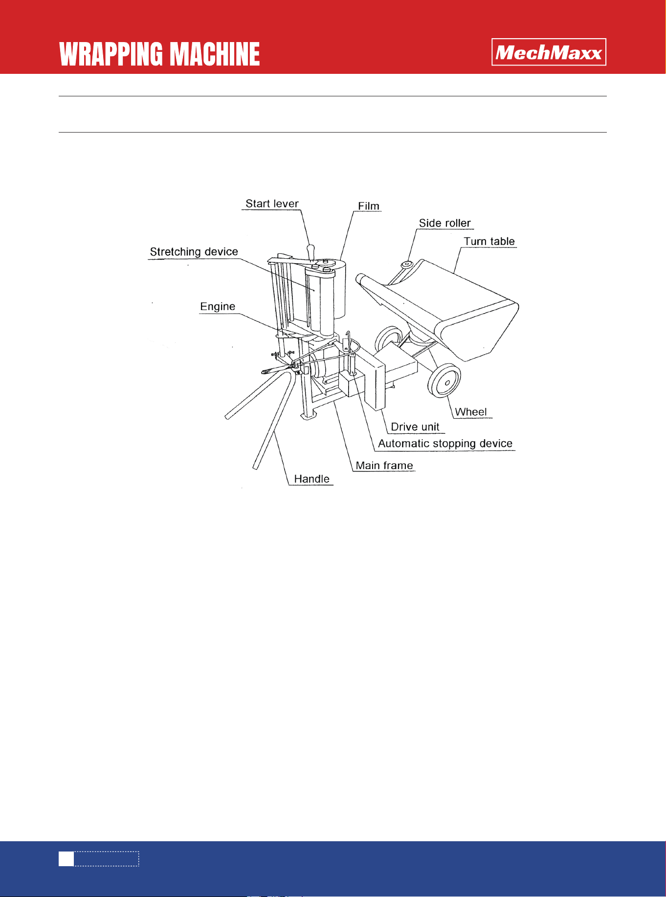
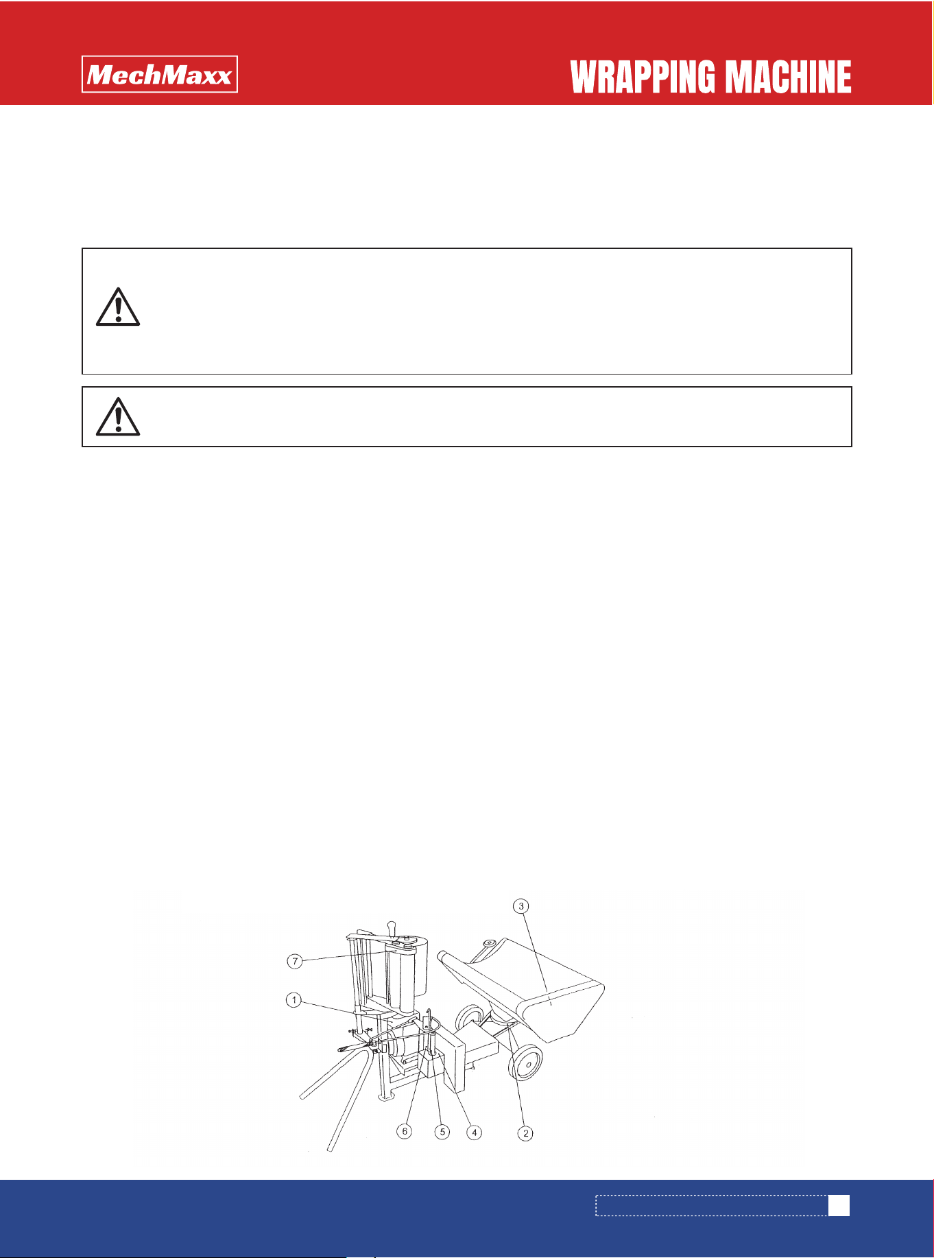
Correctly install for safe operation.
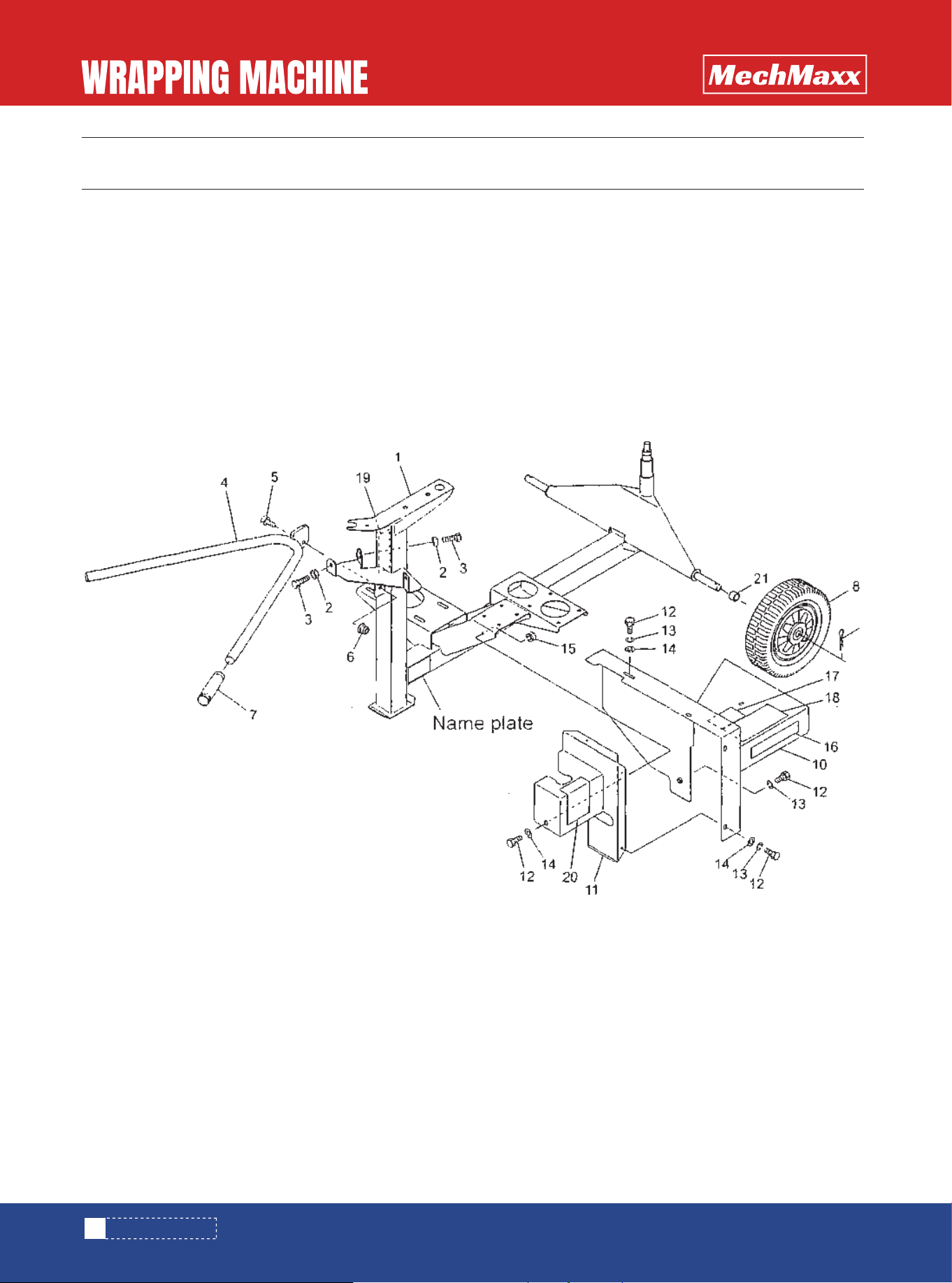
1. Main frame
The main frame supports the engine, drive unit, automatic stopping device, turn table and stretching device.
2. Handle and wheels
The handle and wheels support the machine and can be used to move it.
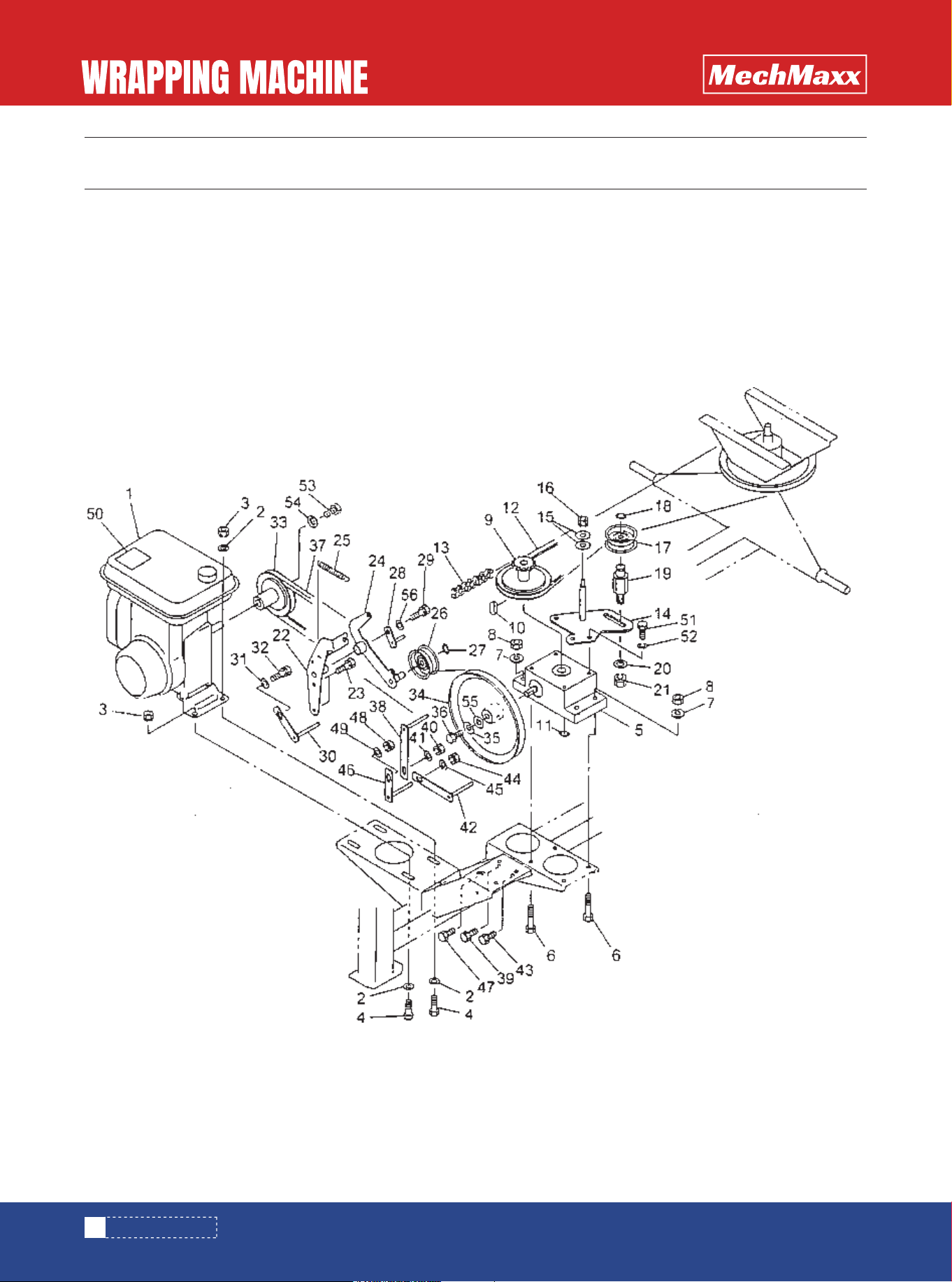
3. Drive unit
The drive unit decelerates the rotation from the engine, and the belt clutch tension is used to transmit the rotation or to
isolate the rotation from the turntable.
4. Automatic stopping device
This device automatically stops the film winding around the bale.
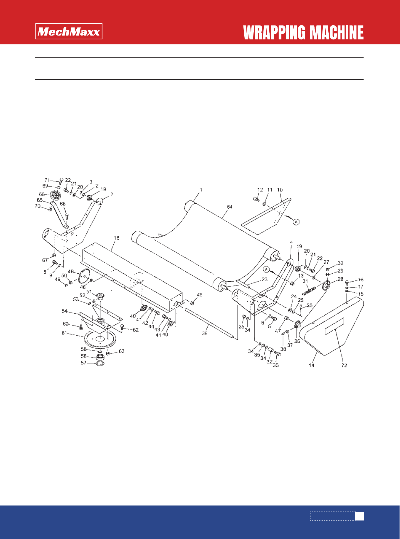
5. Turn table
The turn table has a bale mounted on it and turns it for wrapping it.
6. Side roller
This roller keeps the bale in position, while the bale is wrapped.
7. Stretching device
This device is loaded with a film and stretches the film from the roller driven by the force pulling out the film.
8. Start lever
This lever is used to turn on or off the rotation of the turntable.
1. NAMES AND FUNCTIONS OF RESPECTIVE PARTS
5
www.mechmaxx.com
INSTALLATION
The machine is designed to exhibit its performance when an adequate engine is mounted on it. The engine of the machine
has the following specification.
1.Unpacking
Remove the parts out of the packing frame.
2.List of parts to be assembled
Confirm whether or not all the necessary parts are provided based on the packing list contained in the
package.
3.Assembling procedure
With regard to the bolts and nuts necessary for assembling the respective parts, see the symbols stated
in the packing list.
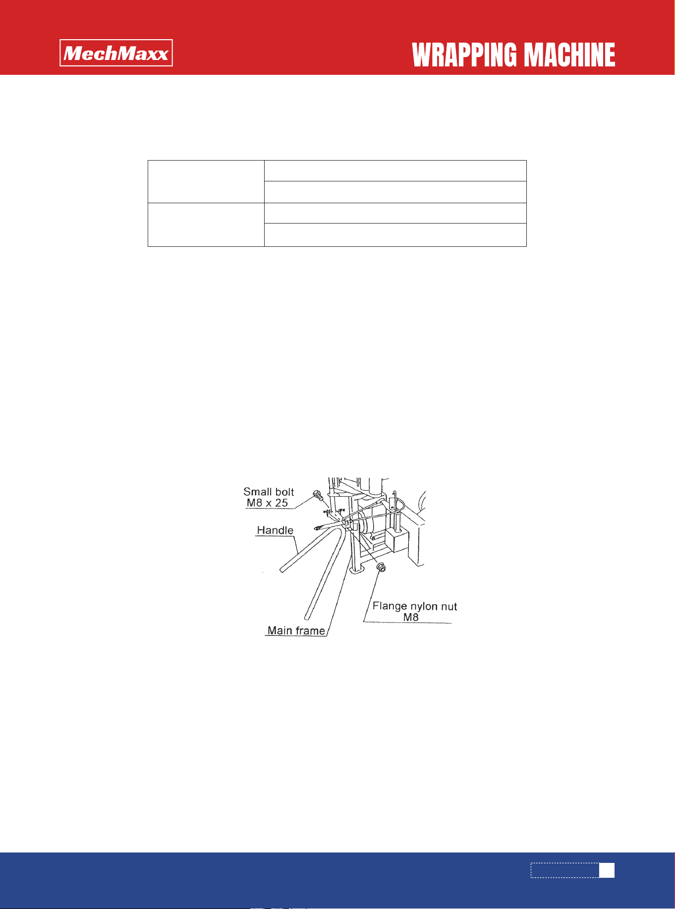
(1)Assembling of handle
Assemble the handle on the front side of the main frame of the machine
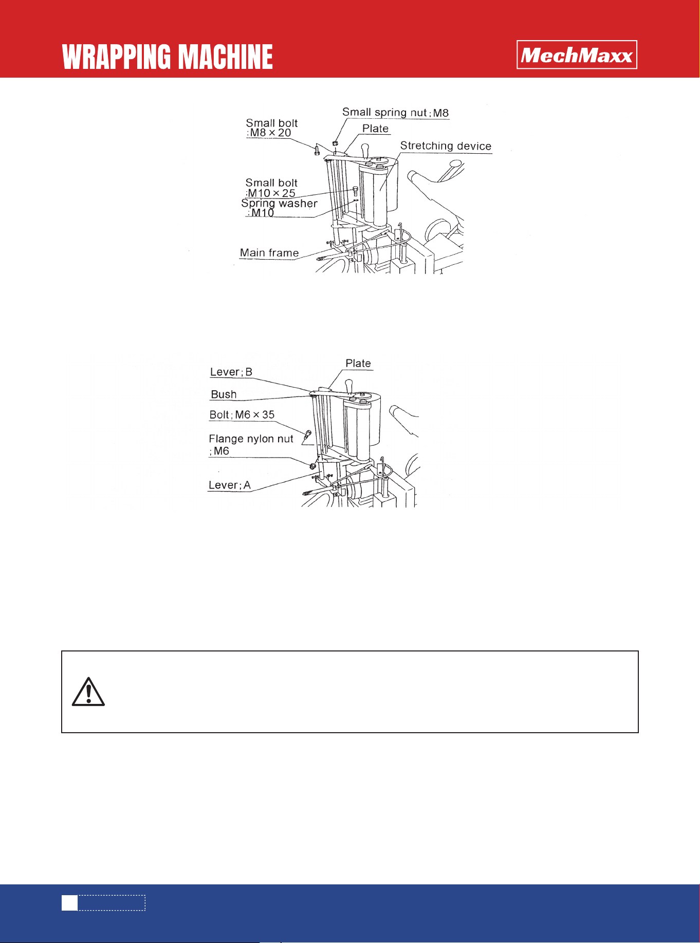
(2) Assembling of stretching device Assemble the stretching device above on the front side of the main frame of the
machine, and insert a bush into the hole at the tip of the plate from above.
2. APPLICABLE ENGINE
3.PARTS TO BE ASSEMBLED
Engine horse power
Maximum 2.0 PS/4,200 rpm
Continuous rating1.4 PS/3,600 rpm
Continuous rating 1.1Kw
Continuous speed 2800rpm
Electromotor
• When assembling, adjust the tightening of the bolt and the flange nylon nut to ensure that the handle can be easily
moved vertically.
PRECAUTION
6
www.mechmaxx.com
INSTALLATION
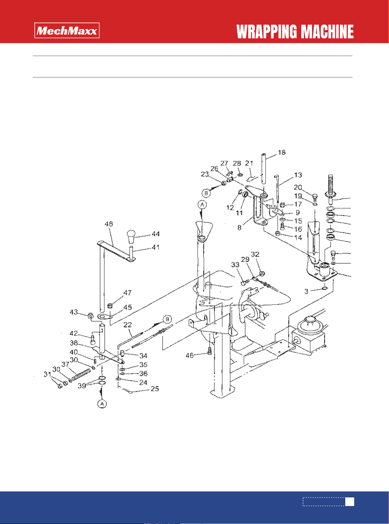
(3) Assembling of start lever
After assembling the stretching device as described in the above 3-3-(2), insert a lever B into the bush portion at the top
of the stretching device, and insert the bush into a bottom lever A, fixing using a bolt and a flange nylon nut.
• If the machine is installed on a slope, rugged ground, weak ground, etc., the machine remains
unstable, and it can happen that the machine begins to move suddenly to cause an unexpected
accident.
• Fasten the wheels on a flat and hard ground place, and firmly fix the machine body.
4.INSTALLATION AND MOVEMENT
• It should be noted that if the bolt and the flange nylon nut are tightened extremely, the pipes of the levers A and В may
be deformed.
PRECAUTION
2. MOVEMENT
1. INSTALLATION

7
www.mechmaxx.com
• If the machine is moved at a high speed on a slope, rugged ground or along a sharp curve, it can
happen that the machine falls down on its side or tumbles down accidentally. Move slowly.
• If the machine is moved on a shoulder of a road with an inclining side or side ditch, it can happen
that the machine tumbles down accidentally.Do not move on a shoulder.
• If it is attempted to move the machine across a large level difference, it can happen that the
machine falls down on its side to injure any person working nearby. Use a footboard.
• If a person rides on the machine, it can happen that the machine falls to injure him/her. Further-
more, if the machine is moved with any thing placed on it, it can happen that the thing drops or
that the machine falls down on its side to injure the persons working nearby.Do not allow any
person or thing to be placed on the machine.
• In the case where the machine is mounted on the load carrying platform of a truck and fastened using a rope or the like,
do not wind the rope around the turn table for fixing it. The machine may be broken.
PRECAUTION
INSTALLATION
8
www.mechmaxx.com
1. INSPECTION BEFORE OPERATION
INSPECTION BEFORE START OF OPERATION
INSPECTION BEFORE START OF OPERATION
Be sure to inspect the machine before start of operation to ensure that the machine can be used for a long period of time
without any problem.
1. Inspection of respective parts of engine
Inspect the respective parts of the engine based on the instruction manual of the engine.
2. Inspection of machine proper
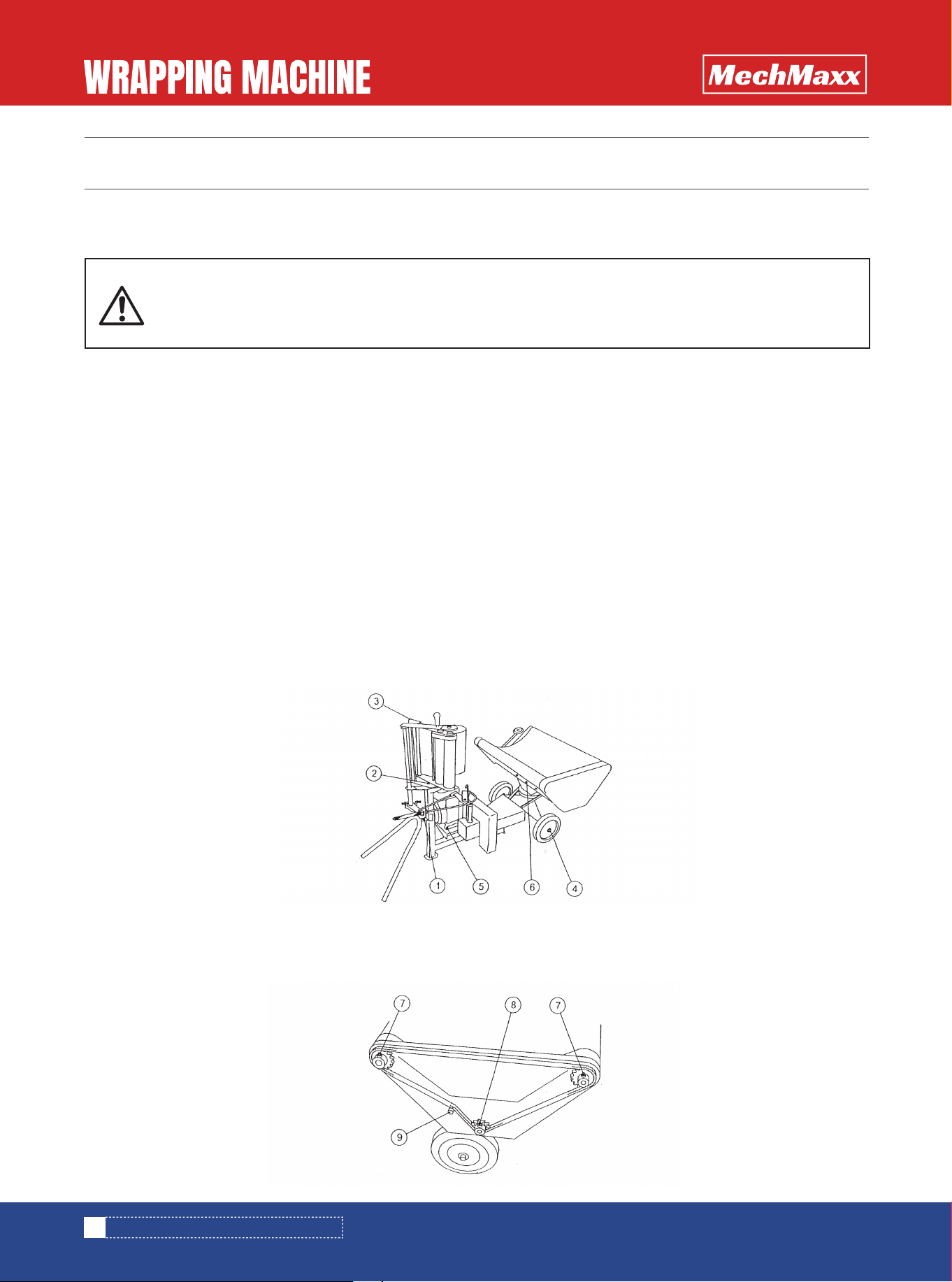
(1) Check whether or not the bolts and nuts of respective parts are loose or whether or not pins come out.
Especially check the following parts carefully.
Symbol (1): Bolt and nut for attaching the handle
Symbol (2): Lower bolt and nut for attaching the stretching device
Symbol (3): Upper bolt and nut for attaching the stretching device
Symbol (4): Cotter pins for attaching the wheels
Symbol (5): Bolts and nuts for attaching the engine
Symbol (6): Bolts and nuts for attaching the turn table
Symbol (7): Bolts and nuts for-attaching sprockets 35-20T
Symbol (8): Bolt and nut for attaching sprocket 35-13T
Symbol (9): Chain tension bolt and nut
• If the inspection before start of operation is neglected, it can happen that the machine is poorly
adjusted and broken or that any person working nearby is injured accidentally. Before start of
operation, inspect the machine based on the instruction manual.
9
www.mechmaxx.com
INSPECTION BEFORE START OF OPERATION
2. INSPECTION AT START OF ENGINE
3. LIST OF OILING AND GREASING POINTS
(2) Check whether the chain tension is too tight or too loose.
(3) Check whether the oil and grease at respective parts is sufficient.If any oil or grease is insufficient, apply the oil or
grease based on the explanation of "2-3 List of oiling and greasing points."
1. Inspection at start of engine
(1) Confirm that the start lever is set at "OFF position.”
(2) Start the engine, and confirm whether or not the engine is normal.For handling of the engine, read the instruction
manual for the engine contained in the package.
(3) Operate the start lever, to rotate the machine, and confirm whether or not any abnormal sound or abnormal vibration
occurs.
(4) If any trouble is found, correct the trouble based on the "6-1 List of trouble corrections."
2. Inspection at start of engine.
(1) Confirm that the start lever is set at "OFF position.”
(2) Start the electromotor, and confirm whether or not the engine is normal.
(3) Operate the start lever, to rotate the machine, and confirm whether or not any abnormal sound or abnormal vibration
occurs.
(4) If any trouble is found, correct the trouble based on the "6-1 List of trouble corrections."
• The oil used for lubrication or coating must be clean.
• When greasing, do it till the new grease is forced out after the old grease has been forced out.
• The machine is filled with oil and grease sufficiently when it is delivered. However, confirm them before use.
• Before starting the engine, confirm that the start lever is set at "OFF position."If the engine is
started with the start lever set at "ON position," the turn table will rotate to injure any person
working nearby.
• If the engine is started indoors as in a house, the exhaust gas may cause poisoning. Open
windows and door for sufficient ventilation.
• Before starting the engine, let the persons working nearby know it and confirm safety.

10
www.mechmaxx.com
*1. For the detail of oiling to the engine (No. 1), see the instruction manual for the engine contained in the package.
*2. If the slide arm shaft face (automatic stopping device) (No. 6) is coated with a grease with a high viscosity, the move-
ment of the slide arm becomes poor.
No.
1 1
1
1
2
3
4
5
6
7
Lubrication point
Engine About 0.4 liter
Every 30 working hours
Every 30 working hours
After use
Grease coating
Grease coating
Grease or oil
Oil
1 Oil
After use
After use
1 Oil After use
1
1
Oil After use
Engine oil for motor
vehicles
Gear (turn table)
Drive chain (turn table)
Drive chain (automatic stopping
device)
Slide arm screw (automatic
stopping device)
Slide arm shaft face (automatic
stopping device)
Gear (stretching device)
Bearings and other sliding
portions
Point Kind of lubrication Change period Remarks
INSPECTION BEFORE START OF OPERATION

HOW TO OPERATE
11
www.mechmaxx.com
1. This machine is used to stretch and wind a film around a cylindrical bale for sealing it, to prepare bale silage for
livestock farming.Do not use the machine for any other application
2. To prepare silage of good quality, do not operate the machine in the case where the grass contains much water due to
rainfall or dense fog, or on a muddy field or highly humid field.Wrap the grass with an adequate water content on a well dry
field as soon as possible after baling.
1. Adjust the water content of grass to 50 to 60%.If the water content is too large or too small, ideal lactic acid fermenta-
tion cannot take place. Especially during rainfall or dense fog, do not operate the machine since the water content is too
large.
2. Preparation of well-shaped bales
Make well-shaped highly dense bales.
3. Sealing immediately after baling
If the sealing is delayed, the temperature inside the bale rises to grow putrefying bacteria and to thermally denature
proteins, thereby lowering the digestibility, not allowing silage with good quality to be prepared.
4. Use a wrapping film with stable quality.
A film likely to greatly change in nature in response to the change of air temperature may be poor in the accuracy of
sealing.
Preserve the film in a cool place free from direct sunshine, to avoid the deterioration during preservation. Do not preserve
the film for a long period of time.
5. If the film used for sealing is damaged to have a hole, be sure to repair it.
If a film is damaged or holed by mistake, be sure to repair it.
If an ordinary tape is used for repairing, it may peel due to water content, solar heat or the like.
6. Reliable preservation
As the place for preserving the silage, select a well drained place and cover the silage with a net, or spray chemicals, or
take any other necessary measure for protecting the silage from the damage caused by birds, rodents, insects, etc.
It is ideal to stack the wrapped bales vertically in two or three stages, for maintaining the sealing accuracy and saving
the preserving space.
The number of stages must be such that the stacked bales do not fall but remain stable and safe.
7. All the unsealed bales should be consumed for feeding within the day.
If silage is exposed to air, secondary fermentation occurs to promote deterioration.
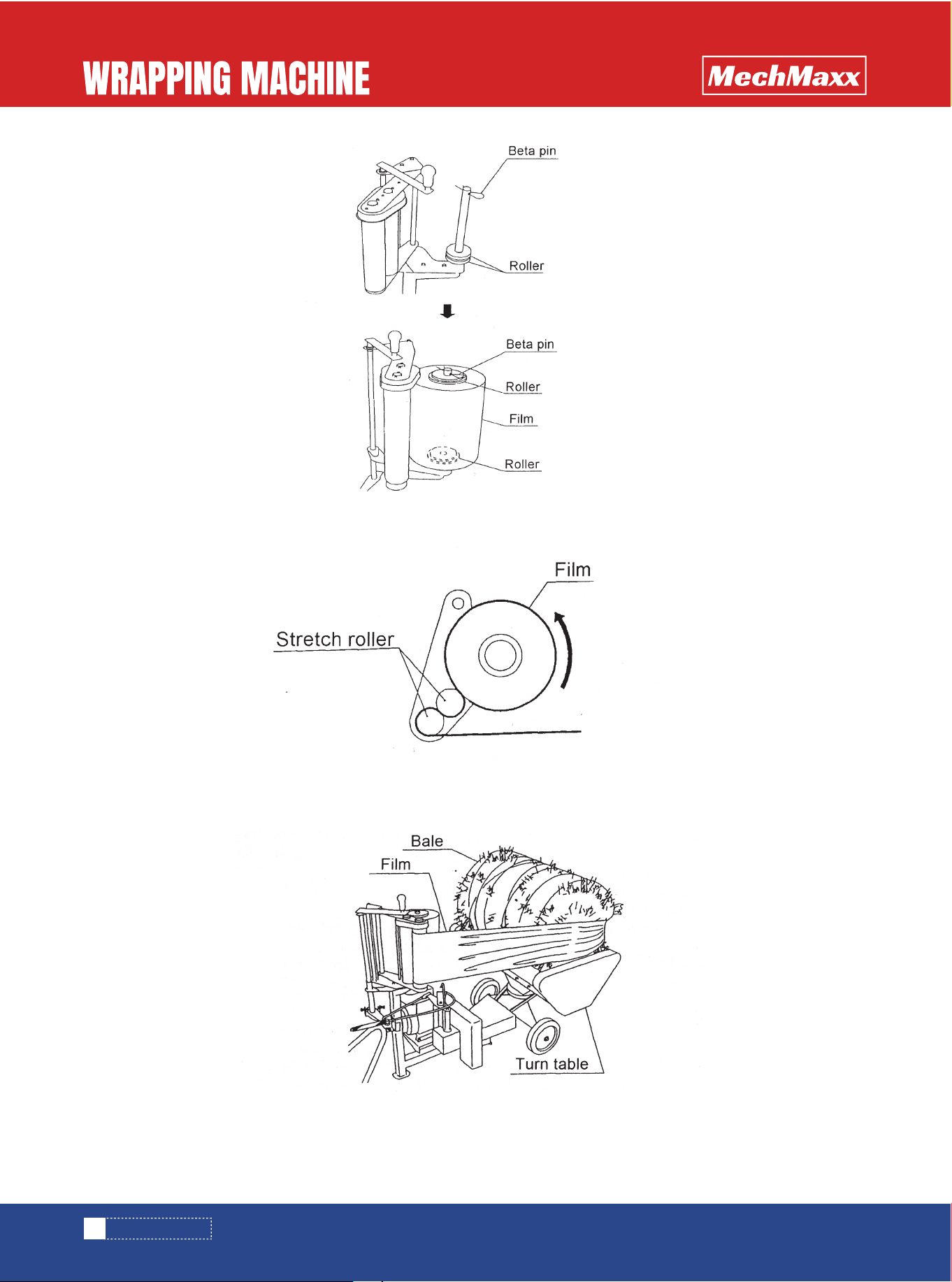
1. Film loading
(1) Remove the beta pin and rollers of the stretching device portion, and set a film. Then, insert a roller into the cylindrical
hole at the top of the film, and fix using the beta pin.
For preparing high-quality wrapped silage.
HOW TO OPERATE
1. PURPOSE OF MACHINE
2. ADJUSTMENT FOR OPERATION
12
www.mechmaxx.com
(2) Insert the film in such a manner that the winding direction observed from above corresponds to counterclockwise
direction.
(3) Pull out the film, and pass it through as illustrated, fastening it with the twine on the bale side.
HOW TO OPERATE
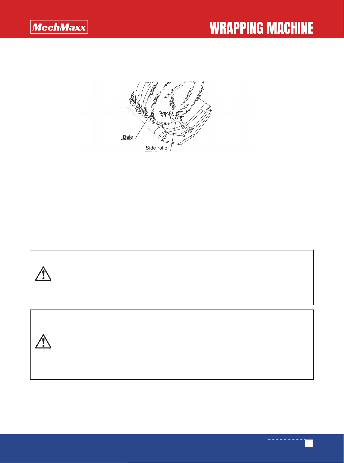
(1) Place the bale to be wrapped, on the turn table alongside the side plate on the drive side (drive chain side).
(2) Adjust the side roller for adaptation to the width of the bale, and fix using a bolt and a nut.
The machine is portable and can be moved. It can be used even near a livestock yarn on a field.
13
www.mechmaxx.com
• If you open any cover during operation or rotation, you may be caught by the rotating portion and
injured. Do not open any cover during operation or rotation.
• If you touch the film or stretch roller while the film is wound, you may be caught and injured. Do
not touch the film or stretch roller during operation.
• If you adjust the machine or remove any deposited matter without stopping the engine, a third
person may carelessly and suddenly drive the machine, to cause an unexpected accident.Stop
the engine and confirm that rotating portion and moving portions are stationary, before you do
such a thing.
• If you touch the turn table or the like during operation or rotation, you may be injured.Do not allow
persons working nearby to approach the machine.
• If an irregularly shaped bale or light-weight bale is going to be wrapped, it may be swung away to
injure any person working nearby. Do not wrap such a bale.
• If the machine is used indoors as in a house, the exhaust gas may cause poisoning.Open windows
and door for sufficient ventilation.
• When adjusting the side roller, keep a spacing of about 30 to about 50 mm between the end face of the bale and the
side roller.
• After completion of adjustment, firmly tighten the bolt and the nut.
PRECAUTION
• Do not handle a bale of more than 30 kg on this machine. Furthermore, do not throw the bale onto the turn table. Other-
wise the machine may be damaged.
PRECAUTION
HOW TO OPERATE
3. WORKING PROCEDURE
2. Adjustment of side roller
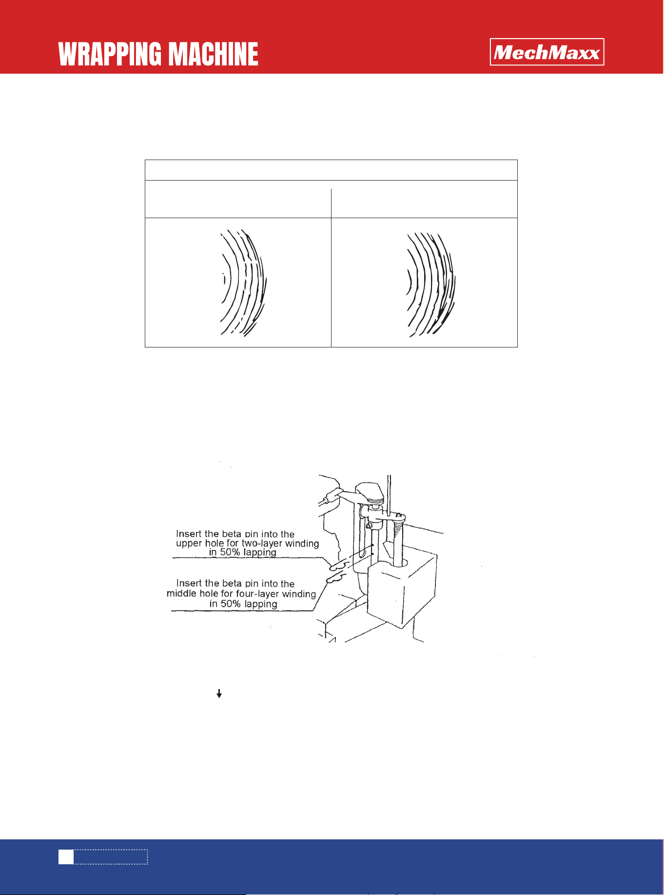
Bale diameter 460 to 500 mm
50% lapping one-turn winding
(two-layer winding)
50% lapping two-turn winding
(four-layer winding)
14
www.mechmaxx.com
(1) Adjust the number of turns of film, depending on the situation.For preserving the bale silage for a long period of time
or for preparing bale silage with good quality, wind the film in four or more layers.
2. METHOD FOR STARTING THE MACHINE
(2) Adjustment of film winding
The film winding can be adjusted to two-layer winding or four-layer winding in 50% lapping.Adjust as follows:
① For two-layer winding in 50% lapping
Insert the beta pin into the "upper hole" of slide arm shaft portion of automatic stopping device.
② For four-layer winding in 50% lapping
Insert the beta pin into the "lower hole” of slide arm shaft portion of automatic stopping device.
(1) Pull the start lever toward the mark side.
The turn table will revolve, and the slide arm portion of the automatic stopping device will decline to the position adjusted
for film winding.
1. NUMBER OF TURNS OF FILM
HOW TO OPERATE
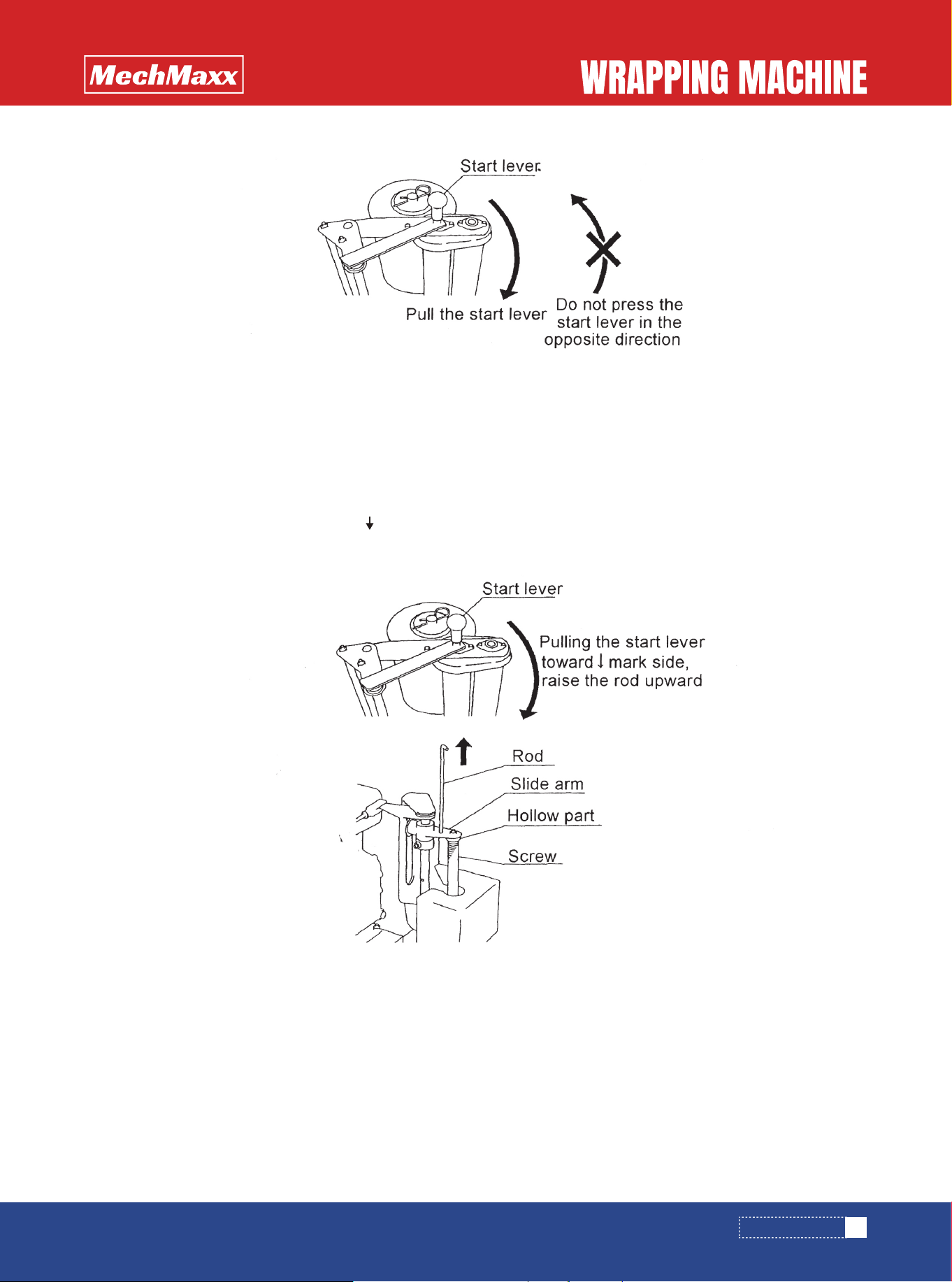
(2) For stopping the operation during winding work, take the following procedure.
① While pulling the start lever toward the mark side, raise the rod on the slide arm portion of the automatic stopping
device upward, for disengaging the hollow part of the slide arm portion from the screw
The rotating speed of the turn table is 40 rpm when the engine control lever is set at the high speed position (rabbit
mark).
Set the engine control lever in a range from the high speed (rabbit mark) to the low speed (turtle mark) for adaptation to
the shape and weight of the bale.
15
www.mechmaxx.com
3. ROTATING SPEED OF TURN TABLE
• Do not press the start lever toward the ↑x mark side. Any damage or trouble will be caused.
• Positively pull the start lever until the slide arm portion of the automatic stopping device completely declines to the
position adjusted for film winding.Unless the start lever is puled sufficiently, the film cannot be accurately wound.
PRECAUTION
HOW TO OPERATE

16
www.mechmaxx.com
• If an irregularly shaped bale or light-weight bale is going to be wrapped, it may be swung away to injure any person work-
ing nearby.Lower the rotating speed for wrapping such a bale.
Work in the following sequence.
(1) Load a bale on the turn table.
(2) Draw the film and fasten it with the twine on the bale side.
(3) Pull the start lever, to start wrapping.
(4) The turn table automatically stops rotation.
(5) Cut the film and dispose of the cut end of the film on the bale side.
(6) Unload and carry the wrapped bale.
PRECAUTION
• Do not handle a bale of more than 30 kg on this machine.Furthermore, do not throw the bale onto the turn table.Other-
wise the machine may be damaged.
• In the case where the winding is considered to be insufficient in view of the condition of the bale, lightly pull the start
lever (to such an extent that the slide arm does not fall) and wind the film by 2 or 3 turns in a state of half-engaged
clutch.
PRECAUTION
4. WORKING METHOD
HOW TO OPERATE
AFTER COMPLETION OF OPERATION
17
www.mechmaxx.com
• If you, for example, remove any material deposited on the rotating portion or any moving portion
without turning off the power, you may be caught in the machine and injured.Stop the engine and
confirm that the rotating portion and moving portions are stationary, before you doing so.
• If you neglect the inspection after completion of operation, the machine may be left improperly
adjusted or left with a broken part or the like, and when the machine is used next time, any trou-
ble can occur or you may be injured. After completion of work, be sure to inspect based on the
instruction manual.
1. Perfectly remove the grass and the like adhering to the machine.
2. Check whether bolts, nuts and pins are loose or come off.Furthermore, confirm whether any part is broken. If any
non-conformance is found, retighten the bolt concerned or exchange the part concerned as the case may be.
CARE AFTER COMPLETION OF OPERATION
1. Clean the respective parts of the machine.
2. Exchange every worn part and every broken part.
3. Add oil and grease based on the list of oiling and greasing points.Apply oil or grease to the rotating portion and sliding
portions of pivots.
4. Touch up damaged coatings or apply oil to them for preventing the generation of rust.
5. Store the machine in a well ventilated indoor space.
FOR STORING THE MACHINE FOR A LONG PERIOD OF TIME
Be sure to take care of the machine to ensure that the machine can be used for a long period of time.
• For washing the machine, do not pour water on the engine.
PRECAUTION
AFTER COMPLETION OF OPERATION
INSPECTION AND MAINTENANCE
Timing
Before use of
new part
Before operation
After operation
Inspection items Correction
18
www.mechmaxx.com
• If any trouble occurring in the machine is left as it is, breakage or injury may be caused. Correct
troubles based on the instruction manual.
• If you carry out inspection or maintenance without stopping the engine, a third person may care-
lessly and suddenly drive the machine, to cause an unexpected accident.Stop the engine and
confirm that the rotating portion and moving portions are stationary, before you carry out inspec-
tion or maintenance
• If you work without installing any cover removed for correcting a trouble, inspection or mainte-
nance, you may be caught in the rotating portion or moving portion and injured. Install the once
removed cover.
Carry out inspection and maintenance periodically so that the machine can be used smoothly without any problem.
To prevent any accident caused by poor maintenance of the machine, inspect and maintain the respective parts based on
the "Inspection and maintenance table," so that the machine can be used in the best condition with peace of mind.
INSPECTION AND MAINTENANCE TABLE
• Whether or not respective bolts, nuts and
pins are loose or come off
• Whether or not respective parts are lubricat-
ed
• Whether or not the rotating portion and drive
system make any abnormal sound
• Clean the machine
• Whether or not respective bolts, nuts and
pins are loose or come off
• Whether or not the rotating portion and drive
system make any abnormal sound
• Whether or not the rotating portion and
moving portions are lubricated, oiled, or
greased
• How is the drive belt tensioned, or isn't it
broken?
• How is the chain tensioned, or isn't it
broken?
• Whether or not any portion is broken
• Clean respective parts
• Whether or not coatings are damaged
• Whether or not pivots, pins and the like are
worn
• Repair
• Paint or coat with oil.
• Exchange the part concerned..
• Retighten or install new ones.
• If any oil or grease is insufficient based on
"2-3 List of oiling and greasing points,"
supply it accordingly.
• Correct based on "6-1 Trouble correc-
tions."
• Retighten or install new parts.
• Correct based on "6-1 Trouble correc-
tions."
• Correct based on ,"2-3 List of oiling and
greasing points."
• Adjust or exchange
• Adjust or exchange.
INSPECTION AND MAINTENANCE
19
www.mechmaxx.com
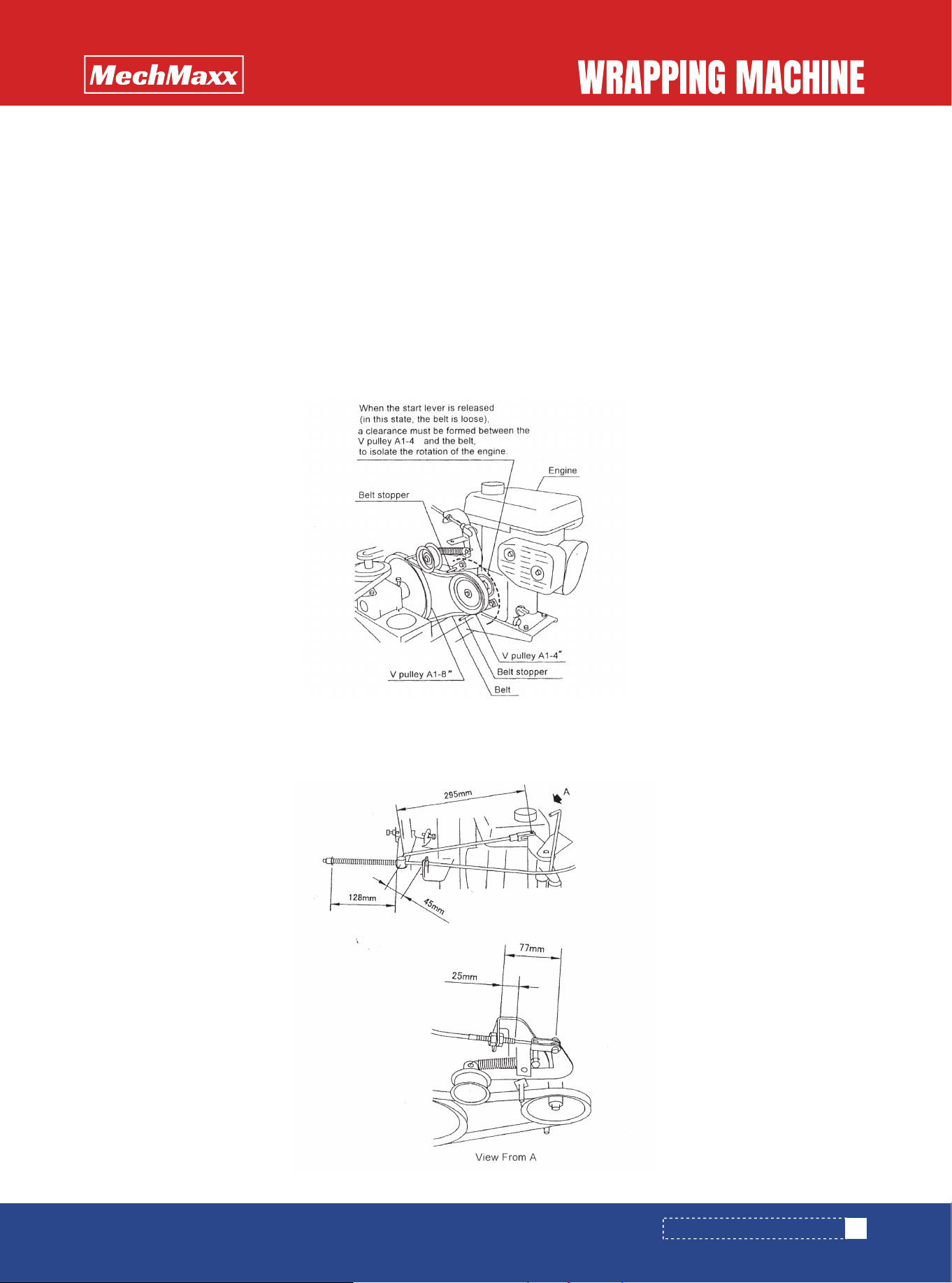
1. Adjustment of belt clutch tension on engine side
(1) Pull the start lever, and move and fix the engine while the automatic stopping device is set at ON position (in this
state, the belt is tensioned).
(2) Adjust to ensure that the clearance between the belt stopper and the belt becomes from 0.5 to1.0 mm.
If the belt stopper and the belt contact each other, noise and heat generation will be caused.
(3) Release the start lever (in this state, the belt is loose), and confirm that a clearance is formed between the V pulley
A1-4" on the engine side and the belt, to isolate the rotation of the engine. In the case where the rotation of the engine
is not isolated, loosen the engine attaching bolts, and move the engine toward the V pulley A1-8" side by 3 to 5 mm, for
re-adjustment and confirmation.
2. Adjustment relating to start lever
With the automatic stopping device kept in OFF state, adjust as illustrated below, and pull and release the start lever, to
confirm that the rotation is transmitted or isolated.
ADJUSTMENT OF RESPECTIVE PARTS
INSPECTION AND MAINTENANCE

TROUBLE CORRECTIONS
20
www.mechmaxx.com
• If the machine has any trouble and is left as it is, breakage or injury may be caused.Correct based
on the instruction manual.
• If you carry out corrective work without stopping the engine, a third person may carelessly and
suddenly drive the machine, to cause an unexpected accident.Stop the engine and confirm that
the rotating portion and moving portions are stationary, before you carry out corrective work.
• If you work without installing any cover removed for correction of any trouble, inspection or
maintenance, you may be caught in the rotating portion or moving portion and injured. Install the
once removed cover.
If the machine does not work smoothly, correct in reference to the list of trouble corrections.
LIST OF TROUBLE CORRECTIONS
Correction
Rotating
portion
Abnormal sound
or abnormal
vibration
Bale does not
rotate.
The twine and
grass are wound
around.
The installation of the machine body
is unstable.
Since the shape of the bale is wrong,
the machine body is shaken.
The shape of the bale is wrong or the
density of the bale is low.
The adjustment of the side roller is
wrong.
The shape of the bale is wrong or the
density of the bale is low.
Since the chain is loose, the sprocket
turns idly without being correctly
engaged with the chain.
Since the shape of the bale is wrong,
the bale does not rotate, and the
sprocket turns idly without being
correctly engaged with the chain.
• Install on flat, smooth and hard ground.
• Fasten the wheels to fix the machine body.
• Make a well-shaped highly dense bale.
• Lower the rotating speed.
• Adjust the chain tension.
• Make a well-shaped highly dense bale.
• Make a well-shaped highly dense bale.
• Readjust for adaptation to the width of the
bale.
• Dispose of the twine to ensure that it
cannot can not be.
• Change the loading direction to ensure that
the bale is rotated in the direction not
allowing the twine to can not be.
The twine wound around the bale is
unwound.
• Make a well-shaped highly dense bale.
Problem Cause
TROUBLE CORRECTIONS

21
www.mechmaxx.com
Correction
Stretching
portion
Driving
portion
Film tension is
insufficient.
The belt slips.
The turn table
does not rotate.
The turn table
does not stop.
As soon as the
rotation starts,
the film is
disengaged from
the bale.
Before the set
number of turns
is reached, the
automatic
stopping device
is actuated to
stop the rotation.
The movement of
the slide arm
portion is not
smooth.
The film is loaded wrongly or passed
through wrongly.
The fastening between the twine on
the bale side and the end of the film
is wrong.
Belt tension is wrong.
Belt tension is wrong.
Belt tension is wrong.
The slide arm portion does not
completely decline to the set position.
• Adjust based on "Film loading."
• Adjust the tension.
• Firmly fasten lest the film should be
disengaged from the bale.
• Adjust the tension.
• Adjust based on "Adjustment of belt
clutch tension on engine side."
• Adjust the tension.
• Adjust based on "Adjustment of belt
clutch tension on engine side."
• Remove dust or the like, and apply oil.
• Remove dust and grease, and apply oil.
Twine comes off of the bale.
Dust or the like is deposited on the
slide arm shaft face.
Since the slide arm shaft face is
coated with grease, the movement
is not smooth.
• The start lever is pulled insufficiently. Pull
the start lever until the slide arm portion
completely declines.
Problem Cause
TROUBLE CORRECTIONS
22
www.mechmaxx.com
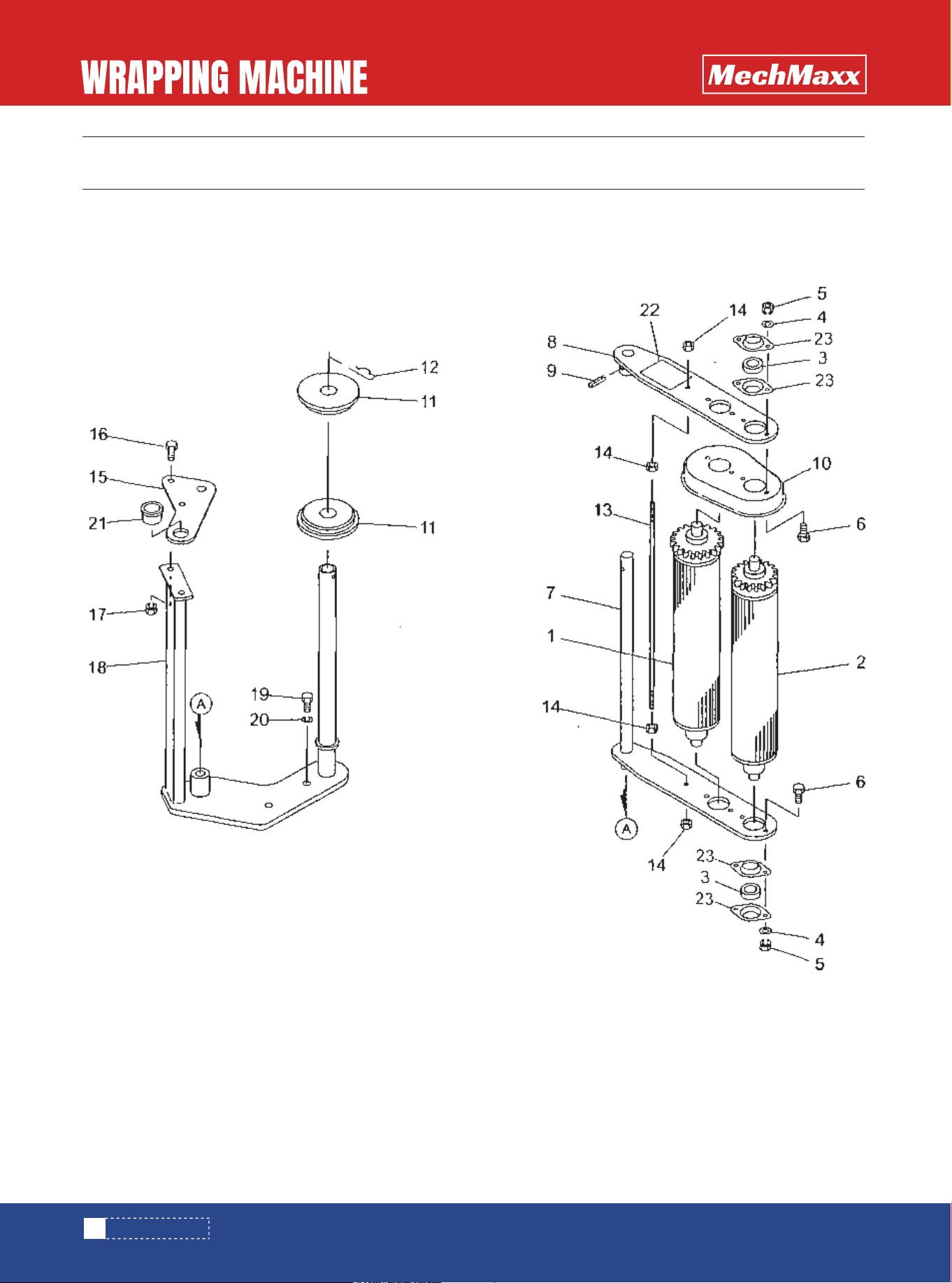
PARTS DIAGRAM
PARTS DIAGRAM

23
www.mechmaxx.com
PARTS LIST
PARTS LIST
1
2
2
1
1
1
2
2
2
2
1
1
6
5
5
1
1
1
1
1
1
No. PARTS NO. QTY
1
2
3
4
5
6
7
8
9
10
11
12
13
14
15
16
17
18
19
20
7002180004
NSZ08
BSZ08035
1297700004
BSZ08025
NNF08
1297730000
7005080000
700520000M
PC040025
1298770007
1298830007
BZ06016
WS06
WRA06
NP06
7020110000
7020160000
7020130000
7020150000
REMARKS
M8 (8)
M8x35 (8.8)
M8x25 (8.8)
M8
cp22.2
cp224><44.5
4x25
_M6X16(3.8]
M6
M6
M6
PARTS NAME
Frame CP
Nut
Bolt
Handle CP
Bolt
Flange nylon nut
Grip
Tire
Sheath
Split pin
Cover CP
Cover CP
Bolt
Sprinq washer
Washer
Spring nut
Label ; l
Label ; 6
Label ; 3
Label ; 5
24
www.mechmaxx.com
PARTS DIAGRAM
PARTS DIAGRAM

PARTS LIST
1
6
4
4
1
4
4
1
1
1
1
1
1
4
2
1
1
1
1
1
1
1
2
1
1
1
1
1
1
No. PARTS NO. QTY
1
2
3
4
5
6
7
9
10
11
12
13
14
15
16
17
18
19
20
21
22
23
24
25
26
27
28
29
R1438050000
080414100M
NSP08
BSZ08025
7001400000
BSZ08030
WSA08
700144000M
KFC0505030
DC016
VA057
LA35058
700151000M
BSPZ06020
028833200M
NP06
000034100M
DC012
700629000M
044098500M
NSP10
129848000M
BSPZ08016
129851000M
077412000M
000034100M
DC012
700194000M
BSZ08016
REMARKS
#8
M8 (4)
M8x25 (8.8)
WPWK04O25-B
M8x3(8.8)
M8
4.5,,-14T
5x5x30
#16
A-57
35x58L
M6x20
#6
M6
#12
#10
M10
M8><16
#H
#12
#20
M8 x 16
PARTS NAME
Engine (EH0920)
Washer
Spring nut
Bolt
Worm gear reducer
Bolt
Spring washer
V-pulley Sprocket CP
Key
Snap ring
V-belt
Roller chain
Bracket CP
Spring nut
Washer
Spring nut
Tension pulley
Snap ring
Shaft
Washer
Sprinq nut
Tension base CP
Bolt with sprinq washer
Tension arm CP
Spring
Tension pulley
Snap ring
Belt stopper CP
Bolt with spring washer
25
www.mechmaxx.com
PARTS LIST

1
1
1
1
1
1
1
1
1
1
1
1
1
1
1
1
1
1
1
1
1
1
1
No. PARTS NO. QTY
30
31
32
33
34
35
36
37
38
39
40
41
42
43
44
45
46
47
48
49
50
044097200M
700179000M
044097200M
BSPZ08016
700627000M
700628000M
700183000M
WS05
BA05016
VA038
700219000M
BSZ08020
NSP08
044097200M
700181000M
BSZ08020
NSP08
044097200M
700179000M
BSZ08020
NSP08
044097200M
7020120000
REMARKS
M8
#50
#8
M8x16(8.8)
A1-4”
A1-8"
M5
M5
M5 x 16(8.8)
A-38
#105
M8x20
M8 (4)
#8
#85
M8x20 (8.8)
M8 (4)
#8
#50
M8x20 (8.8)
M8 (4)
#8
PARTS NAME
Washer
Belt stopper CP
Washer
Bolt with spring washer
V-pulley CP
V- pulley CP
Washer
Spring washer
Bolt
V-belt
Belt stopper CP
Bolt
Spring nut
Washer
Belt stopper CP
Bolt
Spring nut
Washer
Belt stopper CP
Bolt
Spring nut
Washer
Label ; 2
26
www.mechmaxx.com
PARTS LIST
27
www.mechmaxx.com
PARTS DIAGRAM
PARTS DIAGRAM

PARTS LIST
PARTS LIST
2
2
2
4
4
1
4
4
1
2
2
2
1
4
4
4
1
4
8
8
8
1
2
2
2
2
2
4
No. PARTS NO. QTY
1
2
3
4
5
6
7
8
9
10
11
12
13
14
15
16
17
18
19
20
21
22
23
24
25
26
27
28
29
1297760007
130191000M
DC015
1987810007
BSZ08016
WSA08
1297820007
BSZ08016
WSA08
1302050007
WRA06
BZ06016
NP06
1297830007
WRA06
BZ06016
WS06
1297850007
1297910000
WRA06
WS06
BZ06016
129793000M
1297940000
WRA14
PC032020
129795000M
129941000M
NZ06
REMARKS
16.5x1.0
#15
M8x16(8.8)
M8x16(8.8)
M8
M6
M6x16(8.8)
M6
M6
M6x16(8.8)
M6
M6
M6
M6x16(8.8)
10x840
M14
3.2x20
16x11
35-20T
M6 (8)
PARTS NAME
Roller CP
Washer
Snap ring
Side board CP (left)
Bolt
Spring washer
Side board CP (right)
Bolt
Spring washer
Cover CP
Washer
Bolt
Spring nut
Cover CP
Washer
Bolt
Spring washer
Frame CP
Bearing
Washer
Spring washer
Bolt
Collar
Bush
Washer
Split pin
Collar
Sprocket
Nut
28
www.mechmaxx.com

4
1
1
1
3
2
1
2
2
1
2
4
2
2
2
2
1
1
1
2
2
1
2
2
1
1
1
3
1
6
No. PARTS NO. QTY
30
31
32
33
34
35
36
37
38
39
40
41
42
43
44
45
46
47
48
49
50
51
52
53
54
55
56
57
58
60
TRT06020
LA35135
129796000M
BSZ08045
044097200M
NSZ08
700776000M
NZ06
TRT06020
129798000M
1297910000
WRA06
WS06
BZ06016
BZ06016
NP06
129807000M
129808000M
129799000M
NZ06
TRT06020
129800000M
NZ06
TRT06020
1298010007
J6005LLU
J6204LLU
DHC047
DC020
BSPZ08016
REMARKS
M6x20 (10.9)
35 x 135L
1021
M8x45 (8.8)
#8
M8 (8)
35-13T
M6 (8)
M6x20 (10.9)
M6
M6
M6x16(8.8)
M6x16(8.8)
M6
16x4
16x19
40-23T
M6 (8)
M6x20(10.9)
40-13T
M6 (8)
M6x20 (10.9)
#6005-2RS
#S204-2RS
#47
#20
M8x16
PARTS NAME
Set screw
Roller chain
Collar
Bolt
Washer
Nut
Sprocket
Nut
Set screw
Shaft
Bearing
Washer
Spring washer
Bolt
Bolt
Spring nut
Collar
Collar
Sprocket
Nut
Set screw
Sprocket
Nut
Set screw
Boss CP
Bearing
Bearing
Snap ring
Snap ring
Bolt with spring washer
29
www.mechmaxx.com
PARTS LIST

1
4
4
1
1
1
1
1
1
1
1
No. PARTS NO. QTY
61
62
63
64
65
66
67
68
69
70
71
129804000M
BSZ08016
NSP08
1298060000
130174000M
BSZ08025
NSP08
7005590000
028833200M
NZ06
BZ06055
REMARKS
A1-8"
M8x16
M8 (4)
M8x25
M8(4)
90xΦ7
#6
M6 (8)
M6x55 (8.8)
PARTS NAME
V-pulley
Bolt
Spring nut
Belt
Angle
Bolt
Spring nut
Wheel
Washer
Nut
Bolt
30
www.mechmaxx.com
PARTS LIST
31
www.mechmaxx.com
PARTS DIAGRAM
PARTS DIAGRAM

32
www.mechmaxx.com
PARTS LIST
PARTS LIST
2
1
3
4
4
1
1
1
1
1
1
1
1
1
1
2
2
1
1
1
1
1
1
1
1
1
2
No. PARTS NO. QTY
1
2
3
4
5
6
7
8
9
11
12
13
14
15
16
17
18
19
20
21
22
23
24
25
26
27
28
29
30
700299000M
J6202LLUDC015
DC015
129893000M
DHC035
044097200M
BSPZ08020
129899000M
700515000M
J6000LLU
DE008
129906000M
NZ06
129907000M
BJ06020
NP06
700292000M
WS06
BZ06016
000078200M
10511000M
NSZ08
044097200M
PC032016
079424000M
079425000M
044097200M
1299100100
044097200M
REMARKS
35-14T
#6202-2RS
#15
#35
#8
M8x20
#6000-2RS
#8
M6 (8)
Hexagon socket, M6><20 (10.9)
M6
M6
M6
M6x16(8.8)
16^2.3
M8 (8)
#8
3.2x16
8x32
8x32
#8
02.5
#8
PARTS NAME
Shaft CP
Bearing
Snap ring
Bracket CP
Washer
Washer
Bolt with spring washer
Bracket CP
Arm CP
Bearing
Snap ring
Bar
Nut
Top
Flat head bolt
Spring nut
Shaft
Spring washer
Bolt
Snap pin
Rod CP
Nut
Washer
Split pin
Fork end
Pin
Washer
Wire
Washer

33
www.mechmaxx.com
2
1
1
1
1
1
1
1
2
2
1
1
1
1
1
1
1
1
No. PARTS NO. QTY
31
32
33
34
35
36
37
38
39
40
41
42
43
44
45
46
47
48
NSZ08
NNF06
BZ06020
129911000M
WRA10
DE008
129912000M
700297000M
129888000M
PS050032
700296000M
BZ06035
NNF06
1299160000
129921000M
BZ06016
NP06
7020170000
REMARKS
M8 (8)
M6
6x20(8.8)
M10
#8
5x32
M6x35 (8.8)
M6
#12
M6x16(8.8)
M6
PARTS NAME
Nut
Flange nylon nut
Bolt
Pin
Spring washer
Snap ring
Spring
Lever CP (A)
Washer
Spring pin
Lever CP (B)
Bolt
Flange nylon nut
Grip
Plate
Bolt
Spring nut
Label; 7
PARTS LIST
34
www.mechmaxx.com
PARTS DIAGRAM
PARTS DIAGRAM

PARTS LIST
1
1
8
4
8
8
8
1
1
1
1
2
1
1
4
1
2
2
1
2
2
1
1
No. PARTS NO. QTY
1
2
3
4
5
6
7
8
9
10
11
12
13
14
15
16
17
18
19
20
21
22
7006200000
7006240000
700668000M
JCS202LLU
WRA06
NP06
BZ06020
700616000M
700618000M
PS060025
7006150007
1298360000
000088100M
129837000M
NZ06
129838000M
BSZ08020
NSP08
1298390007
BSZ10025
WSA10
7006670000
7020140000
REMARKS
28T
19T
M6
M6
M6x20 (8.8)
6x25
19x3
M6 (8)
M8 x 20 (8.8)
M8 (4)
M10x25 (8.8)
M10
PARTS NAME
Stretch roller CP
Stretch roller CP
Bi-flange
Bearing
Washer
Spring nut
Bolt
Frame CP (A)
Frame CP (B)
Spring pin
Cover
Roller
Snap pin
Shaft
Nut
Plate
Bolt
Spring nut
Frame CP (C)
Bolt
Spring washer
Bush
Label ; 4
35
www.mechmaxx.com
PARTS LIST