Operator’s Manual
www.mechmaxx.com
WARRANTY


IMPORTANT SAFETY INFORMATION
1
www.mechmaxx.com
Thoroughly read and understand the instructions given in this manual before operation. Refer to the “Safety Decal”, read
all instructions noted on them.
Do not allow anyone to operate this equipment who has not fully read and comprehended this manual and who has not
been properly trained in the safe operation of the equipment.
The SAFETY ALERT SYMBOL indicates there is a potential hazard to personal safety involved and extra safety precaution
must be taken. When you see this symbol, be alert and carefully read the message that follows it. In addition to design
and configuration of equipment, hazard control and accident prevention are dependent upon the awareness, concern,
prudence and proper training of personnel involved in the operation, transport, maintenance and storage of equipment.
A signal word designates a degree or level of hazard seriousness. The signal words are:
• Operator should be familiar with all functions of the unit.
• Operate implement from the driver’s seat only.
• Make sure all guards and shields are in place and secured before operating the implement.
• Do not leave tractor or implement unattended with engine running.
• Dismounting from a moving tractor could cause serious injury or death.
• Do not stand between tractor and implement during hitching.
• Keep hands, feet, and clothing away from power-driven parts.
• Wear snug fitting clothing to avoid entanglement with moving parts.
• Watch out for wires, trees, etc., when raising implement. Make sure all persons are clear of working area.
• Turning tractor too tight may cause implement to ride up on wheels. This could result in injury or equipment damage.
SAFETY AT ALL TIMES
LOOK FOR THE SAFETY ALERT SYMBOL
BE AWARE OF SIGNAL WORDS
NEVER USE THE ARMS LIKE A CRANE
DANGER
Indicates an imminently hazardous situation which, if not avoids, will result in death or serious injury. This signal
word is limited to the most extreme situations, typically for machine components that, for functional purpose,
cannot be guarded.
WARNING
Indicates a potentially hazardous situation which, if not avoided, could result in death or serious injury, and
includes hazards that are exposed when guards are removed. It may also be used to alert against unsafe practic-
es.
CAUTION
Indicates a potentially hazardous situation which, if not avoided, may result in minor or moderate injury. It may
also be used to alert against unsafe practices.
IMPORTANT SAFETY INFORMATION

2
www.mechmaxx.com
• Thoroughly read and understand the “safety label” section, read all instructions noted on them.
FOR YOU PROTECTION
• Lower machine to ground, put tractor in park, turn off engine, and remove the ignition key.
• Detach and store implements in a area where children normally do not play. Secure implement by using blocks and
supports.
SHUTDOWN AND STORAGE
• Slow moving tractors, self-propelled equipment, and towed implements can create a hazard when driven on public
roads. They are difficult to see, especially at night.
• Flashing warning lights and turn signals are recommended whenever driving on public roads. Use lights and devices
provided with implement.
USE SAFETY LIGHTS AND DEVICES
• Comply with state and local laws.
• Maximum transport speed for implement is 20 mph. Do not exceed. Never travel at a speed which does not allow
adequate control of steering and stopping. Some rough terrain require a slower speed.
• Sudden braking can cause a towed load to swerve and upset. Reduce speed if towed load is not equipped with brakes.
• Use the following maximum speed - tow load weight ratios as a guideline:
20 mph when weight is less than or equal to the weight of tractor.
10 mph when weight is double the weight of tractor.
• IMPORTANT: Do not tow a load that is more than double the weight of tractor.
TRANSPORT MACHINERY SAFELY
• Riders obstruct of operator’s view, they could be struck by foreign objects or thrown from the machine.
• Never allow children to operate equipment.
KEEP RIDERS OFF MACHINERY
• Understand procedure before doing work. Use proper tools and equipment. refer to Operator’s Manual for additional
information.
• Work in a clean dry area.
• Lower the implement to the ground, put tractor in park, turn off engine, and remove key before performing maintenance.
• Allow implement to cool completely.
• Do not grease or oil implement while it is operation.
• Inspect all parts. Make sure parts are in good condition and installed properly.
• Remove buildup of grease, oil or debris.
• Remove all tools and unused parts from implement before operation.
PRACTICE SAFE MAINTENANCE
• Be prepared if a fire starts.
• Keep a fist aid kit and fire extinguisher handy.
• Keep emergency numbers for doctor, ambulance, hospital and fire department near phone.
PREPARE FOR EMERGENCIES
IMPORTANT SAFETY INFORMATION

3
www.mechmaxx.com
• Protective clothing and equipment should be worn.
• Wear clothing and equipment appropriate for the job. Avoid loose fitting clothing.
• Prolonged exposure to loud noise can cause hearing impairment or hearing loss. Wear suitable hearing protection such
as earmuffs or earplugs.
• Operating equipment safely requires the full attention of the operator. Avoid wearing radio headphones while operating
machinery.
WEAR PROTECTIVE EQUIPMENT
• Escaping fluid under pressure can penetrate the skin causing serious injury.
• Avoid the hazard by relieving pressure before disconnecting hydraulic lines.
• Use a piece of paper or cardboard, not body parts, to check for suspected leaks. Wear protective gloves and safety
glasses or goggles when working with hydraulic systems.
• If an accident occurs, see a doctor immediately. Any fluid injected into the skin must be treated within a few hours or
gangrene may result.
AVOID HIGH PRESSURE FLUIDS HAZARD
Your Flail Mower comes equipped with all safety labels in place. They were designed to help you safely operate your imple-
ment. Read and follow their directions.
1. Keep all safety labels clean and legible.
2. Replace all damaged or missing labels. To order new labels go to your nearest mechmaxx dealer or visit our dealer
locator at AgroJonova.com.
3. Some new equipment installed during repair requires safety labels to be affixed to the replaced component as speci-
fied by mechmaxx. When ordering new components make sure the correct safety labels are included in the request.
SAFETY LABELS
IMPORTANT SAFETY INFORMATION

4
www.mechmaxx.com
INTRODUCTION
INTRODUCTION
Mechmaxx welcomes you to the growing family of new product owners. This implement has been designed with care and
built by skilled workers using quality materials. Proper assembly, maintenance, and safe operating practices will help you
get years of satisfactory use from the machine.
The Flail Mowers are designed for three-point hitch or Quick-Hitch System mounting. These Flail Mowers are ideal for
ripping, leveling, finish grading, and backfilling applications at feedlots, outdoor arenas, building sites, and maintenance
operations on farm and ranch lanes or roadways.
APPLICATION
• This Operator’s Manual is designed to help familiarize you with safety, assembly, operation, adjustments, troubleshoot-
ing, and maintenance. Read this manual and follow the recommendations to help ensure safe and efficient operation.
• The information contained within this manual was current at the time of printing. Some parts may change slightly to
assure you of the best performance.
• To order a new Operator’s or Parts Manual contact your authorized dealer. Manuals can also be printed from the mech-
maxx Service & Support Center by your dealer.
USING THIS MANUAL
“ Right” or “Left” as used in this manual is determined by facing the direction the machine will operate while in use unless
otherwise stated.
TERMINOLOGY
Note : A special point of information that the operator must be aware of before continuing.
Important : A special point of information related to its preceding topic. The intention is that this information should be
read and noted before continuing.
DEFINITIONS
The Warranty Registration card should be filled out by the dealer at the time of purchase. This information is necessary
to provide you with quality customer service. If customer service or repair parts are required contact a dealer. A dealer has
trained personnel, repair parts and equipment needed to service the machine.
The parts on your machine have been specially designed and should only be replaced with genuine parts.
OWNER ASSISTANCE
For prompt service always use the serial number and model number when ordering parts from your dealer. Be sure to
include your serial and model numbers in correspondence also.
SERIAL NUMBER PLATE

5
www.mechmaxx.com
ASSEMBLY AND SET-UP
ASSEMBLY AND SET-UP
Refer to the parts illustration.
ASSEMBLY
1. Be certain that tractor draw bar will not interfere. Move draw bar ahead or remove if required. Draw bar should also be
checked for clearance when unit is being raised for the first time.
2. Align lower link arms of tractor to hitch clevises on mower. Insert lower hitch pins into lower ball swivels and attach
linch pins.
3. Attach tractor top link to upper floating hitch on mower with pin supplied. Secure with lock pin.
4. Adjust tractor top link in or out to place upper hitch pin vertically above or slightly behind lower hitch pins to allow
mower flotation. The mower should be run with the back 15 degrees lower than the front.
TRACTOR HOOK-UP
1.Slide driveline end with extended safety cone over splined shaft of gearbox and secure with attaching device.
2.Slide driveline over tractor’s splined PTO shaft and secure with locking device of driveline.
3.Driveline should now be moved back and forth to insure that it is secure on the PTO shaft of the tractor and mower
gearbox.
4.Attach chain from the driveline shield to one of the upper hitch braces to ensure that the shield does not rotate.
5.Should driveline require shortening:
a. Hold the half-shafts next to each other in the shortest working position and mark them.
b. Shorten inner and outer guard tubes equally.
c. Shorten inner and outer sliding profiles by the same length as the guard tubes.
d. Proper overlap is a minimum of one-half the length of each tube, with both tubes being of equal length.
e. Round off all sharp edges and remove burrs. Grease sliding profiles.
DRIVELINE INSTALLATION
CAUTION
Tractor PTO shield and all mower guards must be in place at all times during operation!

6
www.mechmaxx.com
OPERATING INSTRUCTIONS
OPERATING INSTRUCTIONS
NOTE: Always disengage PTO before raising mower to transport position.
1.When raising the mower to transport position, be sure that driveline does not contact tractor or mower. Adjust and set
the tractor’s 3-point hitch lift height so that the driveline does not contact mower deck in the fully raised position.
2.Be sure to reduce tractor ground speed when turning, leaving enough clearance so that the mower does not contact
obstacles such as buildings, trees or fences.
3.Select a safe ground travel speed when transporting from one area to another. When traveling on roadways, transport
in such a way that faster moving vehicles may pass safely.
4.When traveling over rough or hilly terrain, shift tractor to a lower gear.
1.Clear area to be mowed of objects and debris that might be picked up and thrown by the mower blades.
2.Grass is best cut when it is dry. Mowing wet grass can cause plugging resulting in grass clumps behind the mower.
3.Grass should be mowed frequently as shorter clippings deteriorate faster.
4.If mowing extremely tall grass, it is best to raise cutting height and mow the area, then lower cutting height and mow
a second time at the desired height.
1. Check oil level in gearbox.
2. Check that all plugs in gearbox have been replaced and tightened properly.
3. Be sure all mower knives, bolts and nuts are tight.
4. Be certain all guards and shields are in place and secure.
5. Grease driveline shaft and all other grease fittings.
6. Clear area to be mowed of rocks, branches and other foreign objects.
7. Lower mower to ground. Set tractor throttle at approximately 1/4 open. Engage PTO to start blades rotating.
8. Operate with 540 rpm PTO tractor.
9. At first begin mowing at a slow forward speed and shift up until the desired speed is achieved - maintaining 540 PTO
rpm.
10.Mower knives will cut better at a faster blade speed than at reduced throttle.
11.After mowing the first 50 feet, stop and check to see that the mower is adjusted properly.
12.Do not make sharp turns or attempt to back up while mower is on the ground.
13.Do not engage PTO with mower in the fully raised position. Do not engage PTO at full throttle.
Proper servicing and adjustments are the key to the long life of any machine. With careful and systematic inspection of
the mower, costly maintenance, time and repair can be avoided.
Before beginning to mow, the following inspection should be performed:
TRANSPORTING
MOWING INSTRUCTIONS
OPERATING INSTRUCTIONS
CAUTION
When traveling on public roads, whether at night or during the day, use accessory lights and devices for
adequate warning to operators of other vehicles. Comply with all Federal, State, and local laws.

7
www.mechmaxx.com
OPERATING INSTRUCTIONS
WIRELESS REMOTE CONTROL

8
www.mechmaxx.com
ADJUSTMENTS
ADJUSTMENTS
NOTE: Tractor and mower should be on level ground.
Leveling can be adjusted at the tractor’s 3-point arms and center link.
LEVELING THE MOWER
BELT TENSION
The machines cutting height depends upon the position of the rear roller.
1. Remove the bolts that fix the roller on both sides.
2. Lift or lower both sides of roller in equal measurements.
3. Replace bolts and re-tighten.
CUTTING HEIGHT ADJUSTMENT
The 3-point hitch system on this mower has been designed for front to back flotation when mowing on uneven terrain.
Adjust tractor’s top center link to place the upper hitch pin vertically above or slightly behind the lower hitch pins. The
mower should be run with the back 15 degrees lower than the front.
The hitch can also be adjusted from side to side by turning the adjustment handle. Turn handle until you have achieved
your desired location.
The Belt tension should be checked after the first 20 hours of use. And then every 40 hours of use.
1.Tension on the belt can be adjusted with the belt tension bolt. Turn the bolt until desired tension is achieved. When the
belt has the correct tension the gearbox should be adjusted so that the gearbox extension is running straight (parallel)
with the flail mower. Loosen bolts at the bottom of the gearbox and move gearbox until gearbox extension is running
straight.
2.Excessive tension on the belt may lead to premature failure of belt and drive components.
3-POINT HITCH ADJUSTMENTS
CAUTION
Engage parking brake, shut off tractor, remove key and disengage PTO before making any height adjustments!
CAUTION
Belt drive system under roller tension; use care to avoid bodily harm!
CAUTION
Excessive tension on the belt may lead to premature failure of belt and drive components. Excessive tension on
the belt may also lead to a safety hazard to the operator or bystanders.

Proper servicing and adjustment is the key to the long life of any farm implement. With careful and systematic inspection,
you can avoid costly maintenance, time and repair.
IMPORTANT: Make sure that the knife is the same length as the others on the mower. This will keep the rotor rotation
balanced.
1. Remove bolt and nut.
2. Remove old knife.
3. Install new knife and existing bolt.
4. Secure with nut.
At the end of the working season or when the mower will not be used for a long period, it is good practice to clean off any
dirt or grease that may have accumulated on the mower and any of moving parts.
1. Clean as necessary.
2. Check knives for wear and replace if necessary.
3. Inspect mower for loose, damaged or worn parts and adjust or replace as needed.
4. Store unit inside if possible for longer life.
5. Repaint parts where paint is worn or scratched to prevent rust.
6. Replace all damaged or missing decals.
MAINTENANCE
KNIFE REPLACEMENT
STORAGE
V-BELT INSTALLATION
9
www.mechmaxx.com
MAINTENANCE AND LUBRICATION
MAINTENANCE AND LUBRICATION
CAUTION
For safety reasons, each maintenance operation must be performed with tractor PTO disengaged, mower
lowered completely to ground and tractor engine shut off with ignition key removed.
• After using the mower for several hours, check all bolts to be sure they are tight and check drive belt tension.
• Replace any worn, damaged or illegible safety decals by obtaining new decals from dealer.
CAUTION
Belt drive system under spring tension; use care to avoid bodily harm!
1. Remove belt guard fender and belt cover.
2. Disengage belt tension by loosening belt tension bolt until belt can be removed.
3. With tension relieved from belt remove old belt from pulleys.
4. Tighten belt tension bolt.
5. Reinstall belt guard and belt guard fender.
10
www.mechmaxx.com
MAINTENANCE AND LUBRICATION
Type of Lubrication: Multi-purpose Grease
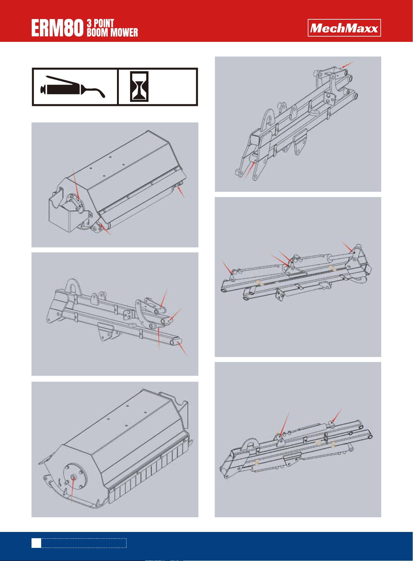
LUBRICATION
25
HOURS
GREASE
GREASE
GREASE
GREASE
GREASE
GREASE
GREASE
GREASE
GREASE
GREASE
GREASE
GREASE
GREASE
GREASE
GREASE
GREASE

11
www.mechmaxx.com
MAINTENANCE AND LUBRICATION
Type of Hydraulic oil: ISO VG 32; ISO VG 46; ISO VG 68
HYDRAULIC OIL
HYDRAULIC OIL
GEAR OIL
SPECIFICATIONS & CAPACITIES
12
www.mechmaxx.com
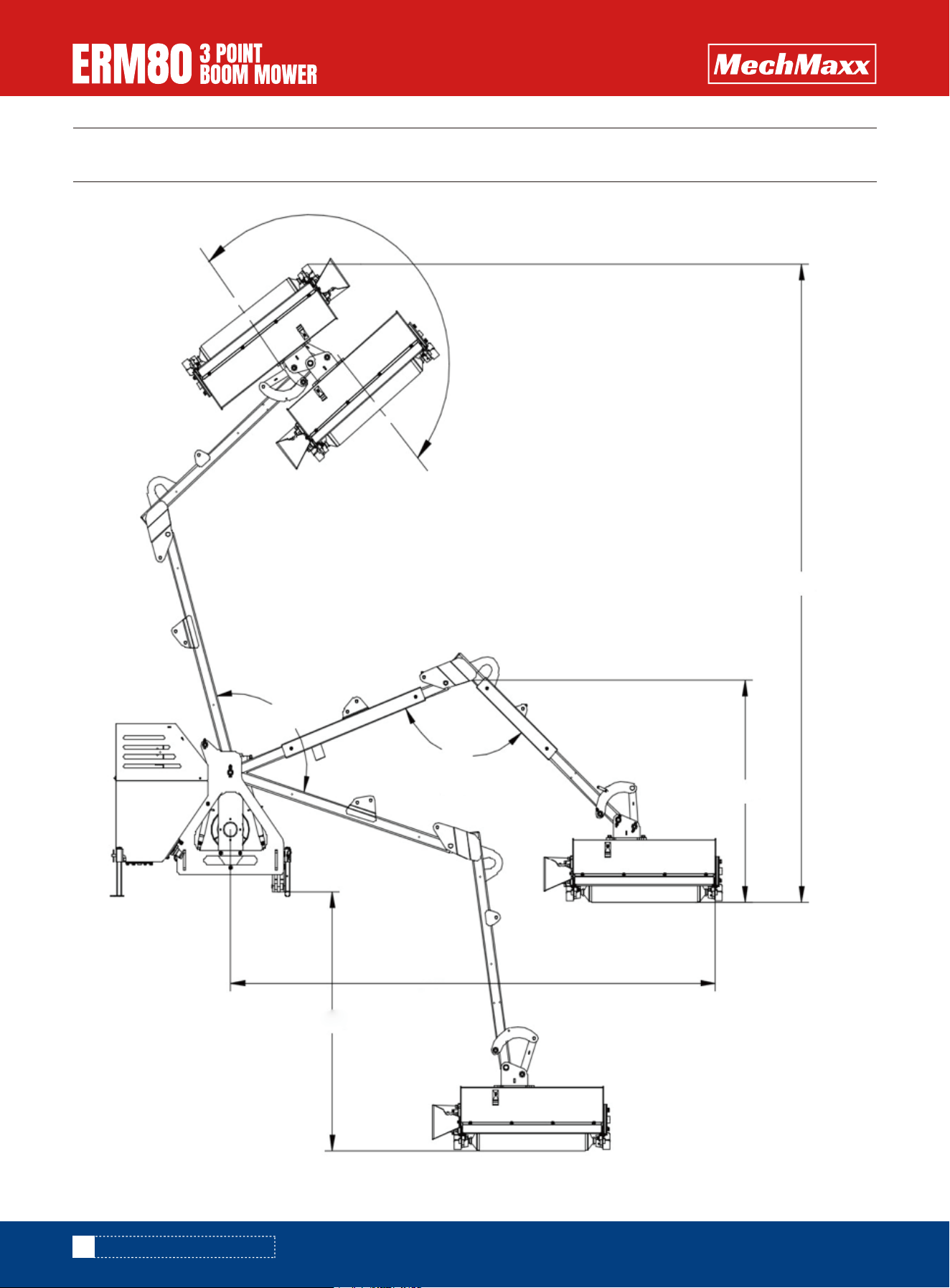
SPECIFICATIONS & CAPACITIES
A: 176°
B: 123°
C: 116°
D:133.8
F:47.2
E:106.2
G:55.1

13
www.mechmaxx.com
Weight
Work width mulch head
Mulch head Y hammer qty
Hydraulic oil flow
Hydraulic oil flow pressure
Hydraulic oil tank volume
Tractor power requirement
Category
Gearbox brand
Wireless Remote control The electromagnetic control valve
Angle A
Angle B
Angle C
Angle D
Distance E
Distance F
Distance G
714 lbs
31.4 in
24
50L/min
20Mpa
70L
20HP
Cat1
Italy CMR
12V
176°
123°
116°
133.8 in
106.2 in
47.2 in
55.1 in
Model ERM80
SPECIFICATIONS & CAPACITIES

14
www.mechmaxx.com
TROUBLESHOOTING
TROUBLESHOOTING
Problem Possible Cause Solution
Motor for hedge cutter
will not operate
Sluggish cutting operation
The motor runs but the
hedge cutter rotor does not
turn
Oil leaks from the motor
Rotor rotates in wrong
directions
The grass is not cut and is
combed and flattened.
Hoses improperly connected to prime
mover
Hoses on prime mover are obstructed
Hoses on boom mower are obstructed
The motor has failed
Insufficient oil flow from the prime
mover
One or more seals have failed in the
motor
Hydraulic filter on prime mover is dirty
Motor shaft has a sheared key Replace key
Replace the linkage. Or replace the
motor.
Replace the bearing
Remove cords, metal strips, … from
the rotor
Replace the washers or replace the
motor.
Replace the seals or motor
Replace seals or fittings
Tighten or replace fittings
Replace the motor
Tighten or replace hoses
Switch hose connections
Reduce travel speed
Replace motor
Avoid thick materials. Adjust to the
maximum diameter of 25 mm
Motor linkage to rotor is damaged
damage of the one of the bearings
something is bended around the rotor
washer/spacers are missing due to the
wrong position of the sprocket.
One or more seals have failed in the
motor
Seals on the fittings are damaged
Fittings are loose or damaged
Drain line hose not connected
directly free to tank
Hoses installed incorrectly
Trying to cut too thick materials or
diameter too big.
Travel speed too fast
Hydraulic motor is failing
Hydraulic hoses are loose or damaged
Connect hoses correctly to prime
mover
Clear obstruction on prime mover
Clear obstruction on broom
Replace the motor
Increase engine RPM
Replace the seals or motor
Replace filter

15
www.mechmaxx.com
Problem Possible Cause Solution
Excessive hydraulic oil
temperature
Hydraulic quick coupler
leaks
Low hydraulic oil level on the prime
mover
Hydraulic hoses are obstructed
Travel speed too fast
Trying to cut material too thick
Hydraulic motor is failing
Hydraulic oil and/or filter on prime
mover are dirty
Replace hydraulic oil and/or filter on
prime mover
Reduce the amount of material being
swept. Make more passes.
Replace motor
Add hydraulic fluid
Clear obstructions in hoses
Reduce travel speed
Quick coupler poppet is unseated or
damaged
Reconnect or replace the quick
couplers
TROUBLESHOOTING
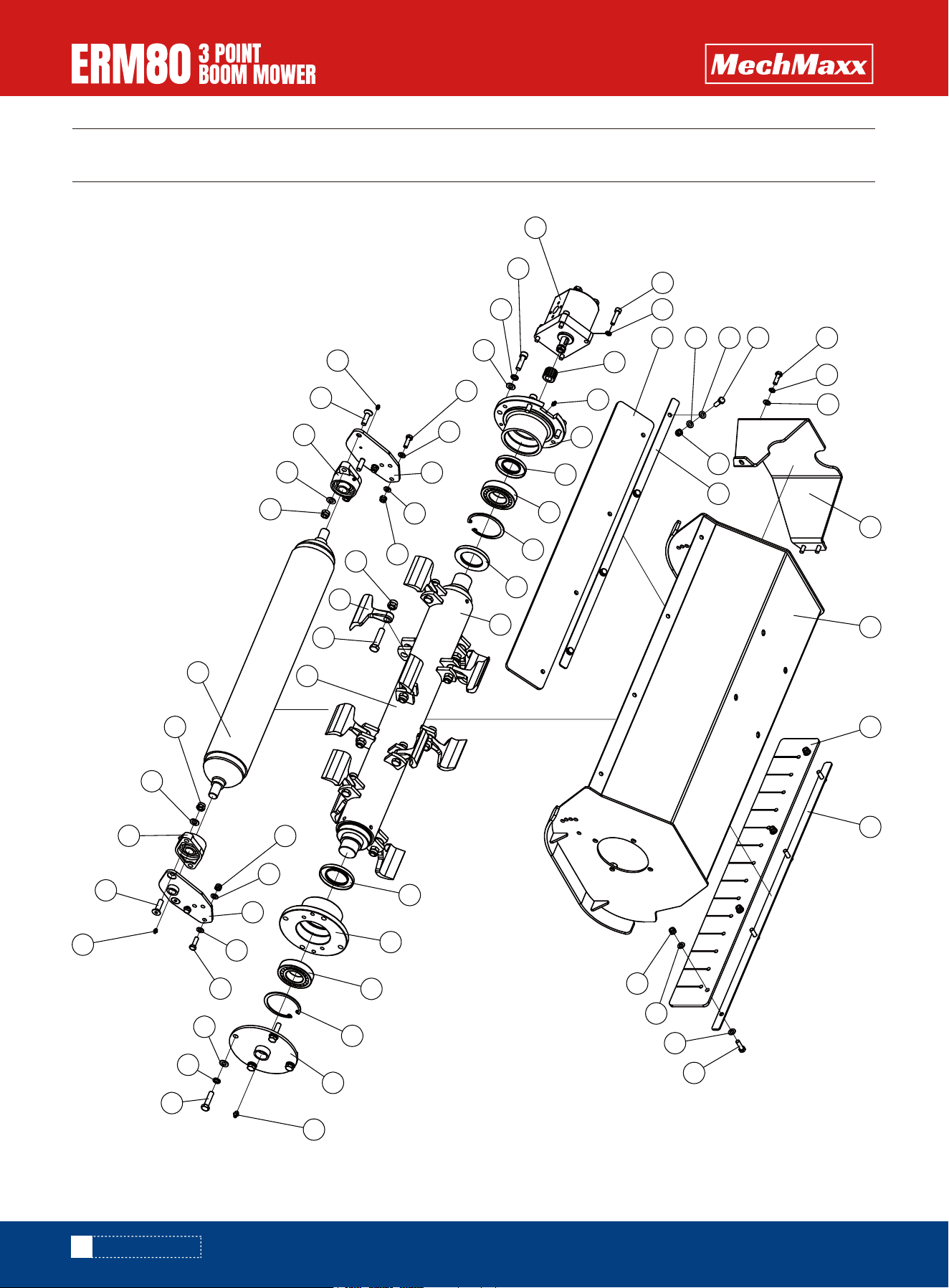
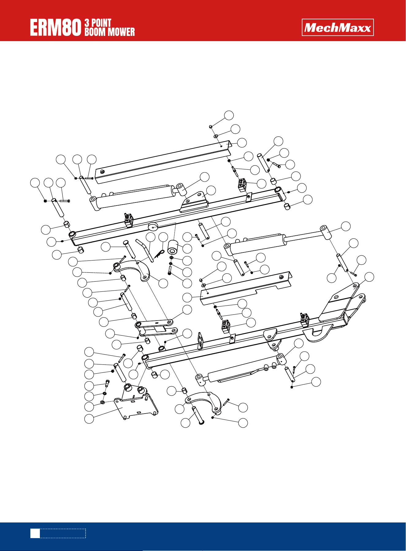
PARTS DIAGRAM
PARTS DIAGRAM
16
www.mechmaxx.com
5 6
4
7 8 9 1
5
4
4
2
5
4
4
2 1
3
22
23
24
25
20
19
18
17
13
12
15
16
16a
16b
16c
15
14
13
12
11
10
25
24
28
5
4
26
4
2
2
4
27
4
5
29
19
30
25
31
32
31
25
30
29
19
21
6
16d

No. DESCRIPTION QTY
1
2
3
4
5
6
7
8
9
10
11
12
13
14
15
16
16a
16b
16c
16d
17
18
19
20
21
22
23
24
25
26
27
28
Rubber pressure plate
Nut M8
Rubber tailgate
Washer 8
Bolt M8*25
Washer 8
Mazda hood
Hood welding assembly
Rubber baffle
Direct-through pressure oil cup M8*1
Bearing seat cover welding assembly
Elastic retaining ring for holes 80
Self-aligning ball bearing 1208
Bearing seat 02
Oil seal FB50*80*8
Knife shaft component
Nut M12*1.5
Hammer
Bolt M12 * 1.5 * 55
Blade shaft welding assembly
Oil seal FB40 * 70 * 8
Bearing housing
Direct injection oil cup M6 * 1
Spline sleeve
Screw M8 * 35
Geared Motor
Screw M10 * 35
Washer 10
Washer 10
Welding component of left hanging plate of drum
Welding components for the right hanging plate of the drum
Bolt M10 * 40
2
12
1
27
15
7
1
1
1
1
1
2
2
1
2
1
12
12
12
1
1
1
3
1
4
1
4
8
12
1
1
4
17
www.mechmaxx.com
PARTS LIST

No. DESCRIPTION QTY
29
30
31
32
Screw M10 * 35
Diamond shaped bearing UCFL204 (double-sided sealed)
Nut M10
Drum welding components
4
2
4
1
18
www.mechmaxx.com
PARTS LIST

MAIN MECHANICAL PARTS 1
19
www.mechmaxx.com
1
3
2
4
5
6
7
8
15 14
16 17 18
19
3
49
48
47
46
45
41
7
40 44
43
42
41 7 40 39 38 37 36 35 34
21
20 21
22 21 23
24
24
21
25
21
33
32
31
30
27 26
27 28 26
9 10
11
7
12
2
3
29
5
13
PARTS DIAGRAM

No. DESCRIPTION QTY
1
2
3
4
5
6
7
8
9
10
11
12
13
14
15
16
17
18
19
20
21
22
23
24
25
26
27
28
29
30
31
32
Fuel tank welding components
Square rubber cover cover cover
3.2R sales
Supporting foot welding assembly 2
Supporting foot pin
O-ring seal
Washer 8
Bolt M8 * 20
Hexagonal plug
Oil drain cap
Oil absorption filter
螺栓 M8*25
Rack welding components
Joint welding components
O-ring seal
Nut M16
Washer 16
Bolt M16 * 130
Locking pin
Upper pull rod pin shaft
Locking pin 8
Lower hanging board 2
Lower hanging board 1
Spherical connecting rod
Lower pull rod pin shaft
Nut M20
Bolt M20 * 55
Arm welding components
Supporting foot welding assembly 1
Nut M6
Pin axis 7
Bolt M6 * 45
1
3
4
2
3
1
19
6
1
1
1
4
1
1
1
2
2
2
1
1
6
1
1
2
2
4
4
1
1
1
1
1
20
www.mechmaxx.com
PARTS LIST

No. DESCRIPTION QTY
33
34
35
36
37
38
39
40
41
42
43
44
45
46
47
48
49
Hanging ear welding components
Bolt M12 * 35
Washer 12
Washer 12
Transmission shaft cover assembly
Join the fork
Upper pull rod pin shaft
Screw M8 * 20
Washer 8
Remote control receiver
Cover plate
Remote control transmitter
Fuel tank cover welding assembly
Screw M5 * 16
Washer 5
Liquid level gauge
Pre pressure air filter
1
4
4
4
1
1
1
9
9
1
1
1
1
6
6
1
1
PARTS LIST
21
www.mechmaxx.com
MAIN MECHANICAL PARTS 2
22
www.mechmaxx.com
PARTS DIAGRAM
1
2
3
4
5
6
7
8
9
10
11
10
12
13
14
16
15
14
13
16 9
7
8
10
11
10
36
25
24 23 22
26
27
29
14
16
28
20
19
14
16
11
1
2
19
16
14
31
14
16
13
31
11
31
333435
11
10
9 7 8 32
4
5
6
21
10
31
30
29
14 16
18
14
17
16
37

23
www.mechmaxx.com
No. DESCRIPTION QTY
1
2
3
4
5
6
7
8
9
10
11
12
13
14
15
16
17
18
19
20
21
22
23
24
25
26
27
28
29
30
31
32
Nut M8
Washer 8
Big arm cover
Nut M8
Threaded rod
Double pipe clamp seat∮22
Pin axis 2
Nut M8
Bolt M8 * 55
Lining SF-2-∮28*∮25*25
Direct injection oil cup M6 * 1
Small arm oil cylinder
Pin axis 1
Bolt M6 * 45
Small arm welding components
Nut M6
Pin axis 4
Implement oil cylinder
Pin axis 3
Push pull welded components
Forearm cover
Screw M10 * 50
Washer 10
Washer 10
Stop block
3.2R sales
Locking pin
Arm plate welding assembly 1
Pin axis 5
Arm plate welding assembly 2
Lining SF-2-∮23*∮20*25
Hitch frame welding assembly
4
4
1
4
4
4
3
3
3
6
5
1
3
8
1
8
1
1
2
1
1
1
1
1
1
1
1
1
2
1
4
1
PARTS LIST

24
www.mechmaxx.com
PARTS LIST
No. DESCRIPTION QTY
33
34
35
36
37
Washer 12
Washer 12
Bolt M12 * 35
Boom cylinder
Arm welding components
4
4
4
1
1
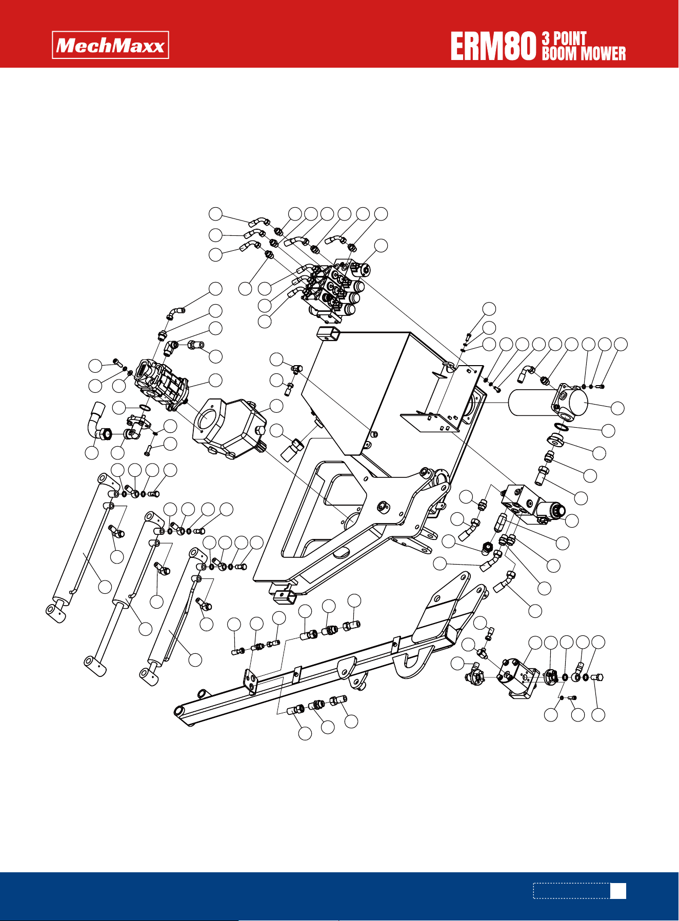
HYDRAULIC LINDE AND DRAIN LINE HOSES
25
www.mechmaxx.com
PARTS DIAGRAM
1 2 3
3
2
1
4
5
3
2
6
7
10
11
12
13
14
15
11
15
29
47
4
48
46
47 49
29 28 27
22 25
47
28 27
47
14
14
16
38
46 45
16
44
43
42
33
34
29
34
29
27
28
30
32
31
33
34
27
34
33
34
28
34
36 35
37
38
39
41 36
40
8
9
15
24
20
25
26
23
15
24
20
23
22
20
17
18
20
19
19
21
6
2

26
www.mechmaxx.com
PARTS LIST
No. DESCRIPTION QTY
1
2
3
4
5
6
7
8
9
10
11
12
13
14
15
16
17
18
19
20
21
22
23
24
25
26
27
28
29
30
31
32
Bolt M8*20
Washer 8
Washer 8
Oil pipe 5
Straight connector M18X1.5-M18X1.5
Screw M8 * 25
Return oil filter
Combination gasket 42
Joint welding components
Straight connector M22X1.5-M26X1.5
Oil pipe 4
Motor control valve group
Bending adjustable joint G1/2-M26X1.5
Straight connector G 1/2-M22 * 1.5
Oil pipe 6
Oil pipe 2
Geared Motor
Joint
Combination washer 16
Oil pipe 15
Articulation bolt M16X1.5X45
High voltage articulated joint G1/4-M14 * 1.5
Oil pipe 17
Direct partition type connector M22X1.5
Oil pipe 10
Direct partition type connector M14X1.5
Oil pipe 8
Oil pipe 11
Oil pipe 13
Boom cylinder
Small arm oil cylinder
Implement oil cylinder
8
20
12
1
1
12
1
1
1
1
1
1
1
3
2
1
1
2
4
2
2
2
1
2
1
1
2
2
2
1
1
1

27
www.mechmaxx.com
No. DESCRIPTION QTY
33
34
35
36
37
38
39
40
41
42
43
44
45
46
47
48
49
Articulated bolt M14 × 1.5 × 35 for pipe joint
Combination washer 14
Bolt M10 * 1.25 * 30
Washer 10
Flange welded parts
Oil pipe 1
O-ring seal
Washer 10
Screw M10 * 30
Dual gear pump
Gearbox
Bent adjustable directional connector G1/2-M22X1.5
Straight connector G 1/2-M16 * 1.5
Oil pipe 3
Straight connector G 3/8-M16 * 1.5
Straight connector G 3/8-M18 * 1.5
Three piece control valve group
6
12
4
6
1
1
1
2
2
1
1
1
1
1
7
1
1
PARTS LIST