
Operator’s Manual
www. mechmaxx.com
WARRANTY


1
www. mechmaxx.com
CONTENTS
CONTENTS
BEFORE STARTING WORK
FOR SAFE WORK
SAFETY PRECAUTIONS FOR OPERATION
DURING WORKING
AFTER WORK
2
2
2
ATTACH TO TRACTOR
NAME AND FUNCTION OF EACH PART
APPLICABLE TRACTOR SIZE
6
6
8
ASSEMBLY
8
ATTACH TO THE TRACTOR
10
ATTACHMENT OF UNIVERSAL JOINT
11
INSPECTION BEFORE OPERATEION
13
INSPECTION BEFORE OPERATION
BEFORE WORKING
WORKING TYPES
3
4
13
13
14
16
16
16
16
INSPECTION BEFORE OPERATION
INSPECTION IN TRACTOR ENGINE RUNNING
LUBRICATION SPOTS TABLE
WORKING METHODS
17
ADJUSTING WHEN WORKING
18
OPERATING MAIN POINTS
20
TRANSPORT
DETACH WITH TRACTOR
AFTER WORK
ARRANGEMENT AFTER WORKING
INSPECTION AND MAINTENANCE
21
21
21
23
23
24
25
25
INSPECTION AND MAINTENANCE TABLE
ALL PARTS ADJUSTMENT
TROUBLE SHOOTING
TROUBLE SHOOTING TABLE
27
PARTS DIAGRAM
28
PARTS LIST
2
www. mechmaxx.com
FOR SAFE WORK
FOR SAFE WORK
SAFETY PRECAUTIONS FOR OPERATION
BEFORE STARTING WORK
Keep the operation manual by the machine
Read operation manual before starting work
Do not operate in the following cases
Neglecting the following precautions can cause a death
or an injury.
Before starting work, read the operation manuals of the
disc machine and tractor carefully to understand the
correct operating method thoroughly.
Check your clothes for work
When lending the machine to a person
CAUTION
▲When you do not know something about
operation of the machine, if the operation
manual is not by the machine, and you judge and
act by yourself, an accident may occur and you
may be injured.
Accordingly, keep the operation manual by the
machine so that you can read it whenever you
want to know something about the machine.
WARNING
▲If you operate the machine in unsuitable
clothes for work, the clothes may be wound in
the machine, and that can cause a death or an
injury.
◇When operating the machine, put on the
following clothes.
◇Clothes, the sleeves and bottoms of which
are not too lose or too long.
Trousers and jacket which are not too loose.
◇Cap
◇Do not wear a towel around your head or neck
or hang it on your belt.
WARNING
▲If you lend your machine to a person who does
not know the precautions and operating procedure
written in the operation manual, he (she) may
cause an accident.
Accordingly, explain the all operation method
and order him (her) to read the operation manual
before starting work.
Prohibition of modification of machine
Execution of check before starting work
CAUTION
▲Modification of the machine or installation of an
attachments or a part which are not recommend
you can cause breakage of the machine and an
injury.
Do not modify the machine.
Use only the attachments which we recommend
you.
Use only replacement parts which are recommend
you.
CAUTION
▲Neglecting check before starting work can
cause breakage of the machine and an injury.
Before starting work, check the machine
according to the operation manual.
CAUTION
▲If you start work without understanding the all
safety precautions and operating procedure
written in the operation manual, an accident may
occur.
Accordingly, before starting work, fully understand
the safety precautions and operating procedure.
Written in the working labels stuck to the
machine and in the operation manual.
WARNING
▲If you operate the machine when your physical
condition is bad of before you get used to operation
of the machine, an accident may occur.
◇Do not operate the machine in the following
cases.
When you cannot concentrate on work because
of fatigue, sickness, doping, etc.
◇After you drink alcohol.
◇When you are not used to operation of the
machine.
◇When you are pregnant.
3
www. mechmaxx.com
FOR SAFE WORK
MINI
DUMPER
T25
DANGER
▲If the right and left brake pedals are not
coupled, only one pedal may be footed on.
It may make sharp turn of a tractor and the
machine and may cause of accident.
Couple right and left brake pedal except special
operation done in the field.
WARNING
▲Never ride together with other people on a
tractor.
Riding together with other people may cause of
accident.
When starting engine and moving machine
When attaching and detaching the machine
When Universal joint is engaged
When traveling
WARNING
▲If you start the engine, standing by the tractor
or on the step of the tractor, you cannot take
proper actions in an emergency and you and
persons around the machine may be injured.
▲Sit on the operator's seat and confirm the
safety around the machine before starting the
engine.
▲If the engine is started with the main gear
shif lever is not the “N” (neutral) position, the
transmission is connected and the tractor
moves abruptly and may cause an accident.
▲Accordingly, when starting the engine, set the
main gear shift lever in the “N” (Neutral) position.
If the tractor is started sharply, its front wheels
may rise and you may be thrown off and persons
around the tractor may be injured.
▲Accordingly, confirm the safety around the
tractor and start it slowly.
▲If you start the engine indoor, it may a cause of
gas-poisoning.
Wide open a door or a window for ventilation.
▲If start the engine without disengaging PTO, it
may cause of injury by sudden machine running.
Start the engine after disengaging PTO.
WARNING
CAUTION
▲Attaching to a tractor,when tractor moves
persons around the machine may be injured.
Make sure none is around the machine.
▲Attaching to a tractor on inclined, uneven or
soft ground, a tractor may suddenly move and
may cause of injury.
Always attach the machine to a tractor on solid
ground.
▲If you detach the machine from a tractor
without putting the wheel chock between tier
and ground, the machine may suddenly move
and may cause of injury.
Whenever detach the machine from a tractor,
stand on the ground and apply the wheel chock
to a tire.
If you attach the machine to a tractor whose
front wheels weight balance is light, it may
cause of loosing control and may cause of injury.
Attach front weight to a tractor to get stable
weight balance.
DANGER
CAUTION
▲If the Universal joint is used in missing cover,
you may be wound in it and be injured.
Never use the Universal joint if missing cover.
▲If the Universal joint is used in broken cover,
you may be wound in it and be injured.
Replace broken cover immediately.
Check the cover if it has any danger before
operation.
Stop engine and disengage PTO when the
Universal joint is attached to a tractor and the
machine.
▲If the Universal joint is used without attach-
ing the cover chain, the cover may rotate and
may cause of injury.
Attach the cover chain to immovable part of a
tractor and the machine.
▲If the Universal joint is rotated in less than
100mm lapping length at the most extracted
position, the Universal joint may be broken and
may cause of injury.
If the clearance is less than 25mm at the most
retracted position, the Universal joint may push
up.
▲It may cause of breakage of the Universal joint
and may cause of injury.
Use the Universal joint under correct lapping
length.
If the clamp pin is not set in the groove of the
shaft, the Universal joint may come out and may
cause of injury.
Make sure if the clamp pin is set in the groove of
the shaft by pushing and pulling the yoke.
4
www. mechmaxx.com
FOR SAFE WORK
DURING WORKING
DANGER
▲If a person touches the pickup or the discs
while the disc mower is operating, he (she) may
be wound in and injured.
Stones will fly out once met the rotating discs,
thus cause injury.
Do not allow any person approaching the disc
mower.
WARNING
▲Do not allow people approach the disc mower
while it is working. People may be wounded into
the machine and cause injury.
▲If the PTO speed exceeds the specified speed
of the disc mower, the disc mower may be
broken and persons around it may be injured.
Observe the specified revolving speed.
When working
WARNING
▲If the tractor is parked on a slope or an
uneven ground, it may run away to cause an
accident.
Park the tractor on a level and hard place and
stop the engine, then apply the parking brake to
prevent the tractor from running away
When leaving the tractor
CAUTION
▲If the tractor is driven without turning off the
power for the disc mower, persons around the
disc mower may be wound in the rotary parts to
injure them.
When driving the tractor, turn off the PTO
CAUTION
▲While lifting and loading the discs, if people
approaches, injury may be occurred.
Do not let people around to approach the
machine.
Do not put hand in.Hand may be suck in and
cause injury if hand was put in from the cover
opening.
While working on slops, if people is too close to
the inclined facets, the sideslip and lateral
overturned may cause unexpected injury.
Do not too close to inclined facets, slow down
working speed.
When adjusting and removing sundries, if the
PTO shaft and engine was not stopped, another
person may drive it by mistake to cause an
accident.
Before touching the disc mower, turn off the
PTO shaft and stop the engine and check that
the rotary parts and movable parts are stopped.
▲Do not stop suddenly or do not turn tightly.
Tractor should be slow down on slopes, uneven
ground and during tight turn.
▲Always take enough distance from other
people and obstruction during turn.
Stay away a person from inner tire of tractor and
the machine or keep enough distance between
inner tire and obstruction when you make
turning.
▲Driving on shoulder of a road, the side of which
is sloped or which have a side ditch, the tractor
may tip over. Do not drive on the shoulder.
▲If you drive over a high obstacle, the tractor
may tip over and you may be injured.
Use ramps to over such an obstacle.
If a person ride the disc mower, he (she) may
fall and may be injured.
▲If anything is pit on the driven disc mower, it
may fall to injure persons around it.
Do not allow a person or a thing on the disc
mower.
If the tractor is moved without setting the draw
bar in the moving position, it may collide with an
obstacle and cause an injury.
When moving the tractor, set draw bar in the
moving position.
▲If you allow a person sit on the disc mower,
he may fall and may be injured. If load things on
the machine, the fall offthings will cause people
around it being injured.
Do not take people,off things on the disc mower.
If you drive down a slope, the tractor may run
away.
Drive slowly on the slope.
▲If the gear is shifted on the a downhill road,
the tractor may run away.
Select a lower gear before the downhill road and
drive down slowly.
▲If you take your eyes off the road while driving
the tractor, you may fail in avoiding an obstacle
or a person to cause an accident.
▲If you release the steering wheel of the
tractor during travel, the tractor may run away.
Hold the steering wheel tightly while driving.

5
www. mechmaxx.com
FOR SAFE WORK
AFTER WORK
When cleaning the machine body
Execution of check after finishing work
Storage
Checking, adjusting and maintaining.
CAUTION
▲If you remove sundries from the rotary parts
or removable parts without turning off power,
you may be wound in the machine and injured.
Before touching the disc mower, make sure you
turn off the PTO and stop the engine and check
that the rotary barts and movable parts are
stopped.
CAUTION
▲If you neglect the check after work, the
machine may be stocked with problems or
broken and you may have a trouble or may be
injured when you operate the machine next time.
Do check the machine according to the operation
manual.
▲If you lift the machine using 3-point linkage
and checking the machine, a third person may
not attended this, the discs loading suddenly
may cause accident.
Please firstly lock the 3-point linkage oil-way,
and then do checking
CAUTION
▲If you lay the disc mower in vertical, the disc
mower may turnover and people may be injured.
Please lay the disc mower in horizontal for
storage in case of turnover.
CAUTION
▲If you dismantle the safety device without
loose the controlling rack spring, 3P frame will
turnover to the main body, people may be
nipped, and injury occurred.
▲When the machine is abnormal and being
neglected, it may cause injury and accident. Do
according to the instruction manual.
▲If working at slopes or uneven or soft ground,
the shaking tractor and disc mower may cause
unexpected accident.
Work on even and hard ground.
▲If the PTO and engine was not stop, and
another person drive the disc mower,will cause
unexpected accident.
Stop the PTO and engine and make sure the
rotary part and movable part were stop, then do
checking.
▲If the machine is in lifting condition, people
may be injured if he plunge in or foot plunge in.
Prop the machine with a stand before plunge in.
▲The hydraulic connectors and pipes, if loose
or damaged, the poured high press hydraulic oil
and the sudden fall down disc mower may cause
accident.
Mend or change the part.
When detach the connector and pipes, please
take out the pressure in the hydraulic hoses.
▲The covers take out from the machine when
checking and adjusting, if working without
installing this cover people will be roll in by
rotating and movable part, and cause injury.
Put back the covers to its original place.
ATTACH TO TRACTOR
6
www. mechmaxx.com
ATTACH TO TRACTOR
(pillar)
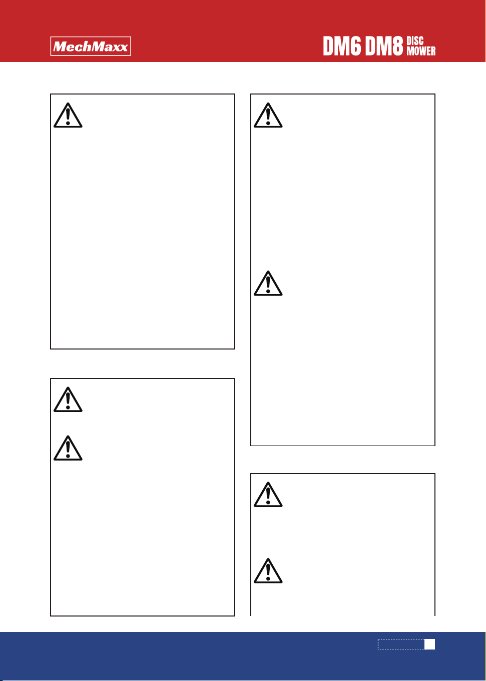
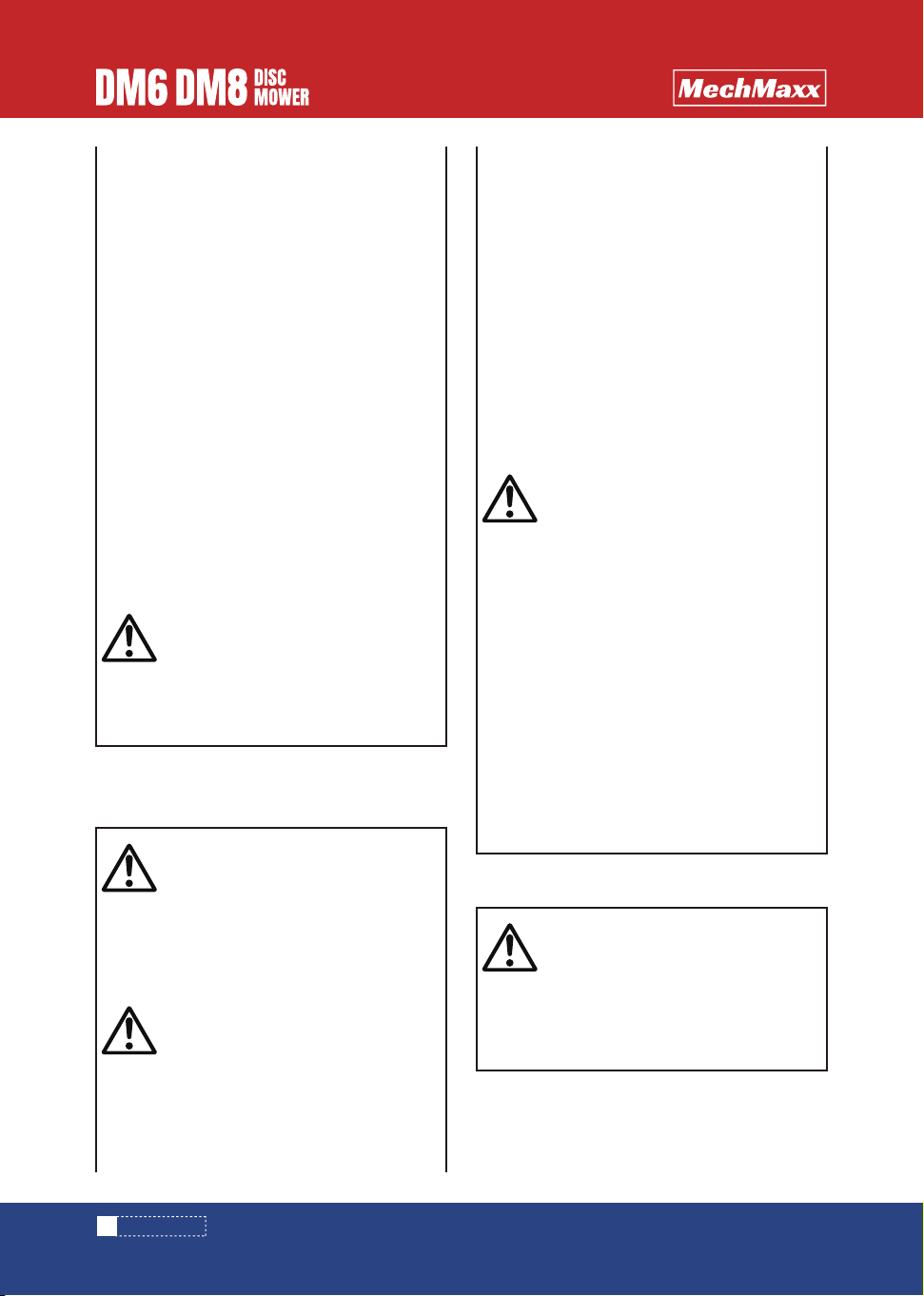
NAME AND FUNCTION OF EACH PART
When cleaning the machine body
(23 1Cylinder
7
www. mechmaxx.com
ATTACH TO TRACTOR
side disc
side disc
middle disc
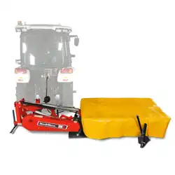
DM6 DM8
8
www. mechmaxx.com
ATTACH TO TRACTOR
APPLICABLE TRACTOR SIZE
ASSEMBLY
This machine is designed to perform by attaching to
suitable size of the tractor.
If this machine is attached to unsuitable size of tractor, it
will have a possibility of giving bad affection to durability
or to operation.
Please prepare a tractor can match this disc mower,
If you use a tractor smaller than the matched tractor,
will cause the disc mower work abnormally because
heavy load.
In reverse, if you use a tractor bigger than the matched
tractor, this machine will damage earlier because of
long-time high pressure
Connect the tractor and disc mower.
When the disc mower started with meeting obstacles
or abnormal power during work, the discs will move
backward, and avoid the disc mower being damaged.
The raising and fall of the discs was controlled by
hydraulic device.
DM6 25.7-58.8kw (35-80HP)
DM8 26.8-73.6kw (50-100HP)
Applicable tractor HP
1. 3P frame
2. Safety device
Open the iron crate and take out all the parts.
Make sure if all parts delivered in accordance with packing
list.
Refer to the mark numbers on nuts and bolts necessary
for assembling in the packing list.
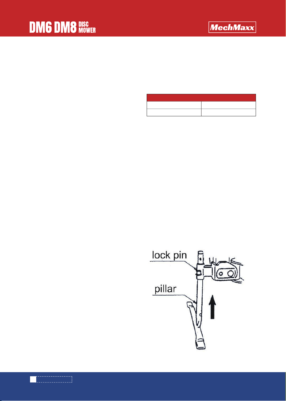
(1) Insert the pillar to the hole at the middle of the 3P
stand, and insert the lock pin.
1. Open the package
2. Details of attached parts
3. Process of assembling
3. Adjusting bar device (hydraulic)
Used to the hydraulic oil circuit of the disc mower, while
raising and fall.
4. Stop valve
Used to adjust the speed of raising and falling of the
discs.
5. Throttle
Ease the duty of grounding load of the disc mower, and
make the discs suitable to the working condition on the
ground.
6. Spring of adjustment bar, suspending device
Switch the suspension device between working and
moving.
7. Location pin
Prevent the flying stones and soil made by the discs
and flying blade.
10. Protecting device, protecting cover
Stop the folding discs at middle, make turning easier.
8. Stop plate
Adjust the cut grass into a line.
9. Grass collecting plate
9
www. mechmaxx.com
ATTACH TO TRACTOR
(4) The condition of the disc mower on the ground, lift
the 3P frame.
The hydraulic lifting device should be installed on the
bar (rear).
(5) After installed the hydraulic lifting device , make
sure to insert the pin to the suspension device.
(6) Install lifting spring on the 3P frame and controlling
bar (front). Install size:DM=270, (the length from the
install place of 3P frame to the lifting spring).
(7) Install safty protection stand on the jacking stand.
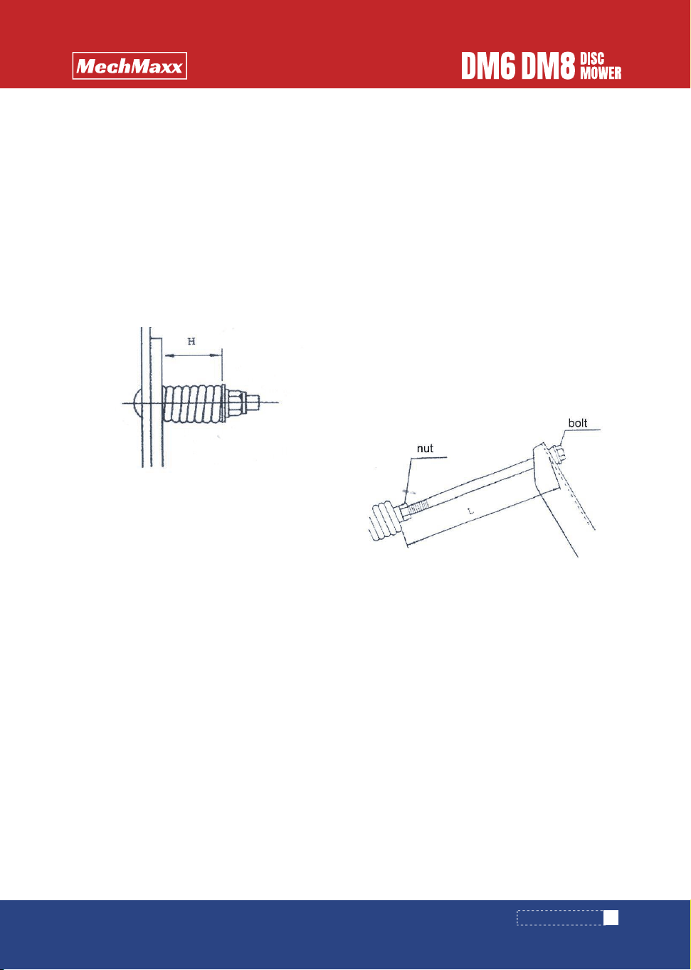
(2) Use the square neck bolt, spring, washer, and nut to
fix on the grass-collecting plate at the back of the disc
mower, so to assemble the grass-collecting plate AS
Assemble size of spring : 6×25×48, H=42mm standard.
(3) Hydraulic lifting device should be installed on the
top of the connecting frame.
Thrust bearing, and spacer bush install like the above
photo.
10
www. mechmaxx.com
ATTACH TO TRACTOR
ATTACH TO THE TRACTOR
(4) If the width of lower link is small, adjust the link of
left side (look from backward) internal.
(5) Lift the 3P machine by 3P connection to let the 3P
frame upright rise choose the position of main link pin
then connect and fix.
(6) Start engine of the tractor and operate the oil pres-
sure handle to lift the machine then stop the engine.
(7) Align center of PIC shaft and PTO shaft by check
chains and then tighten check chains to protect the
machine swing.
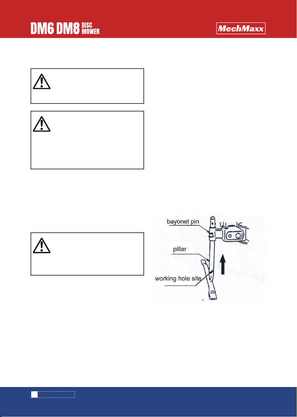
(8) Move the pillar upward, and lock by bayonet pin.
(9) 3P device down, put the machine down.
Lower link pin species:
DM6 (hydraulic): lower link pin Il
DM8: lower link pin Il
When the lower link coupling is not the same, use the
lower link coupling bush, or change lower link coupling.
While changing lower link coupling, loose the spring on
control bar, and take out safety device.
(1) Start engine of the tractor and drive a tractor to
backward until tips of lower link will be aligned.
Stop engine and apply parking brake.
(2) Insert left side of lower link pin into the hole of left
lower link pin.
Insert right side of lower link by same procedure above.
(3) Turn adjusting screw to get the same height of left
and right lower links from the ground.
CAUTION
▲Bystanders must keep safely distance when
the machine is attached to the tractor or
detached from the tractor.
CAUTION
▲While attaching the disc mower to the tractor
on uneven ground, slopes, or soft ground, the
tractor will move by itself, injury maybe
happened.
Attach the machine to the tractor or detach the
machine from the tractor on flat and solid
ground.
CAUTION
If take out the safety device without loose
the spring on control bar, 3P frame will lean
to the main frame, people may caught and
accident occurred.
1. Attach 3P
11
www. mechmaxx.com
ATTACH TO TRACTOR
This machine use one-way cylinder, quick coupling size
is 1/2 inch.
There is also a throttle valve use to adjust the disc
lifting speed, and a stop valve to control the hydraulic
circuit.
(1) Make a mark of the end of the outer safety cover at
the most retract position on the inner safety cover
before installing the power joint.
(2) Pull out other tube of universal joint from inner tube
of universal joint.
(3) Lift up the machine and stop the lifting at the
closest distance PTO shaft and PIC shaft.
(4) Push cramp pin of yoke and insert the yoke into PTO
shaft and push on until cramp pin comes out by spring
force.
(5) Insert the other yoke into PIC shaft same procedure
as mentioned above.
(6) Put one universal joint on to one another universal
joint.
Mark lapping end position of outer safety cover and
inner safety cover and mark at further 25mm inside
from lapping position.
Cut off safety cover at further 25mm position.
(7) lift the machine and stop lifting at the most sepa-
rated position between PTO shaft and PIC shaft.
(8) Put one safety cover on to one another cover.
(9) If lapping length is less than 100mm, replace it to
longer universal joint.
ATTACHMENT OF UNIVERSAL JOINT
DANGER
▲Never use universal joint with damaged
safety cover or without safety cover.
▲Inspect damage is found out on universal
joint.
▲Stop the tractor engine and disengage PTO
clutch when universal joint is attached.
▲Fix chains of safety cover to the tractor and
stationery part of the machine not to rotate
safety cover.
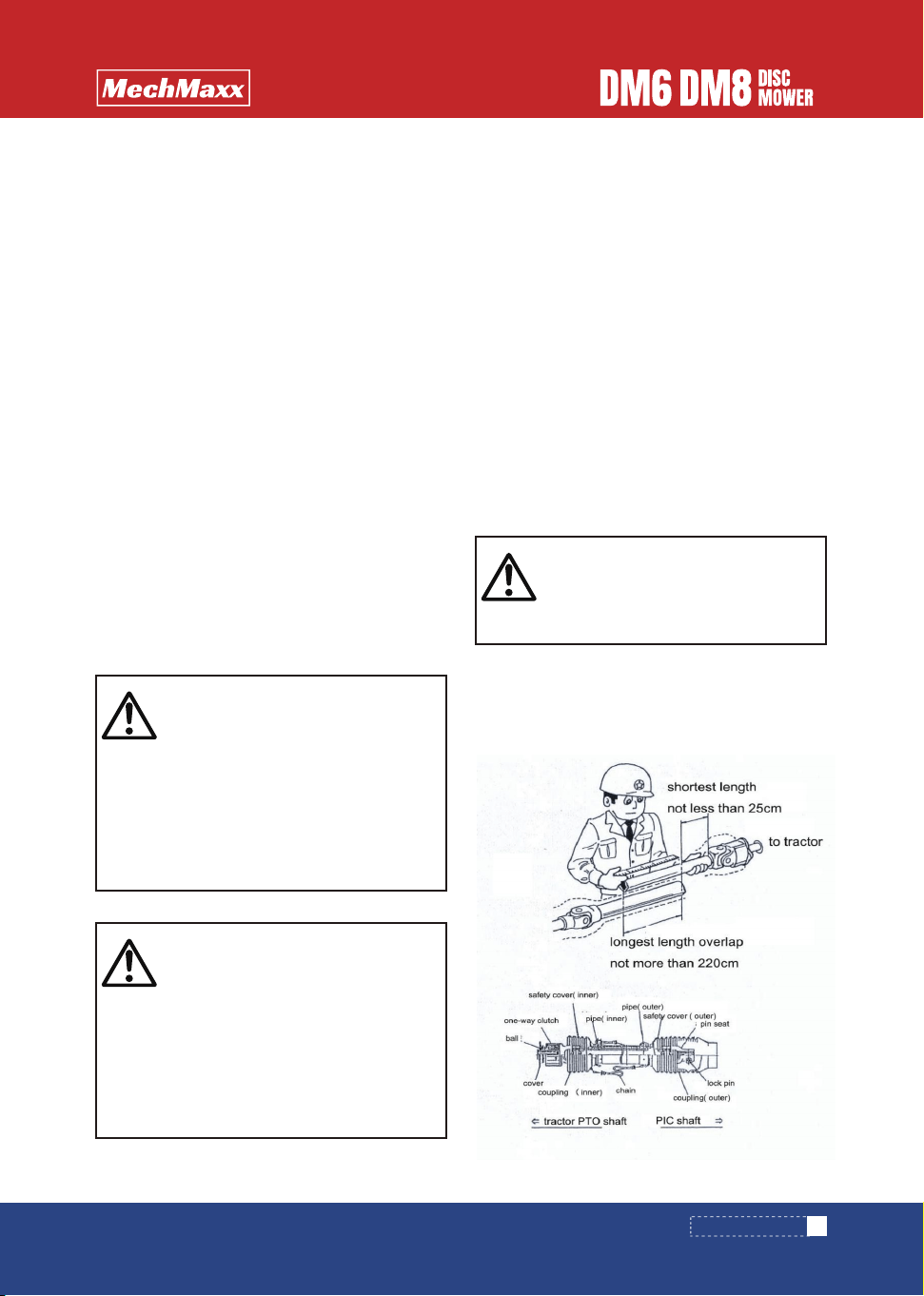
IMPORTANT
▲While safety device work, the distance
between PTO and PIC shaft is 120mm, do not
cut over.
DANGER
▲If overlap length between inner and outer tube
of universal joint is less than 100mm in extend-
ed position, it will be a cause of universal joint
breakage.
▲If the space between inner and outer tube is
less than 25mm in retracted position, it will be
a cause of damage.
By pushing to each other when the machine is
lifted.
2. Attaching to tractor hydraulic output 1. Universal joint length check

12
www. mechmaxx.com
ATTACH TO TRACTOR
(1) Cut off excess length
inner and outer safety
cover.
A. Apply oil to slide loop
channel and tube inside.
(2) Mark on inner and
outer pipe the same
length of cut off safety
cover from the end inner
and outer tube.
(1) Disassemble procedure
of cover
A. Take out fix screw
B. Revolve the cover to
the position of release
C. Pull out safe cover
from tube
D. Take out the slide loop
(3) Before cutting off,
put rag into between
safety cover and pipe not
to come into sawdust.
Cut offexcess length of
tube by metal saw.
(4) File cut ends and clean the surface.
Apply grease on tube and insert inner tube into outer
tube.
E. Fix the position with fix screw.
(1) Connection to the machine
Push cramp pin of yoke and insert yoke into PIC shaft
and push on until cramp pin comes out by spring force.
(2) Connecting to the tractor
Push cramp pin of yoke and insert the yoke into PTO
shaft and push on until cramp pin comes out by spring
force.
(2) Assemble procedure of cover
2. Method of cutting
B. Open the cut mouth of
slide loop and imbed it to
the channel of tube
C. Fit the safety cover.
D. Screw the cover tightly.
3. Method of outer safety cover removal
4. Connection of universal joint
Safety cover
chain
13
www. mechmaxx.com
INSPECTION
INSPECTION BEFORE OPERATEION
INSPECTION BEFORE OPERATION INSPECTION IN TRACTOR ENGINE RUNNING
1. Inspection of the tractor parts
1. Checking driving system
2. Check tractor hydraulic system
3. Check disc mower hydraulic system
2. Inspection of connecting parts
3. Inspection of the machine
Inspect the tractor parts in accordance with operation
manual of the tractor.
Idling first if the machine is new or use after long time
storage.
(1) Start the tractor engine, run in low speed and attach
to the PTO shaft.
(2) Keep the tractor engine speed at 1000rpm, about
5-6 minutes, check whether there is abnormal.
(3) If no abnormal, change PTO running speed to
500-540 rpm, idling about 5 minutes.
(4) Check whether the one-way clutch of the coupling
works when the tractor PTO stops, there is no problem
when stop running and make sound at the same time.
(2)Operate the tractor hydraulic power, fold the disc
mower into half way, close the stop valve, and tractor
hydraulic control bar go back to the original position, it
will be normal if the discs don't descend.
(3) Check the lifting speed of discs.
If too fast, turn the dial of throttle valve to right to
reduce lifting speed.
If problem occurred, mend oil leak point or change parts.
Operate tractor hydraulic to lift 3P linkage, no problem if
there is no descend after lifting.
If there is problem, please contact with the tractor
seller.
(1) Please fold the front part of the safety device.
(1) Inspection of 3P connecting parts
① Make sure that locking pin is inserted into the hole
of lower link pin.
② Make sure that check chains of the tractor are
sticked firmly.
③ If any problem is found in connection, solve the prob-
lem according to the instruction“Page 10 attachment to
tractor”.
(2) Inspection of universal joint
① Make sure that cramp pins stay in the groove of PTO
shaft and PIC shaft.
② Make sure that chain of safety cover has excess
slackness.
③ Check the damage on safety cover of universal joint.
④ If any problem is found on universal joint, solve the
problem according to the instruction “Page 11 attach-
ment of universal joint”.
(3) Inspection of hydraulic system
① Make sure the quick connection of hydraulic system
is connected.
② Check the lockage of stop valve, control bar condition,
disc lifting is on close state.
③ Whether the hydraulic pipe is excess and sag,
whether there is moderate remain.
④ If any problem is found, solve the problem according
to the instruction“Page 10”.
(1) Check looseness of nylon nuts and bolts.
Tighten loosen nuts and bolts firmly.
(2) Check looseness of nylon nut.
Tighten loosen nuts firmly.
(3) Check the length of pick up tension if the length is
improper, adjust the length in accordance with the
instruction of“Page 12’
(4) Check whether there is oil leak of hydraulic system.
Mend the leaking point or change part if problem
occurred.
(5) Check looseness of nuts and bolts.
Tighten loosen nuts and bolts firmly.
(6) Check whether there are enough oil and grease.
If it is not enough, add oil in accordance with the
instruction“Page 14”.
WARNING
1. If the machine started before cut down the
PTO shaft, it will cause injury to the standbys.
Stop the PTO shaft then start the engine.
2. When starting the engine, injury may be
occurred by the lifting of the machine if didn't
descend the disc mower.
CAUTION WHEN OPERATING
If fold the discs without fold the safety device,
the safety device will be damaged in touching
the tractor tires and cabin. Fold the safety
device, then lift the discs.
14
www. mechmaxx.com
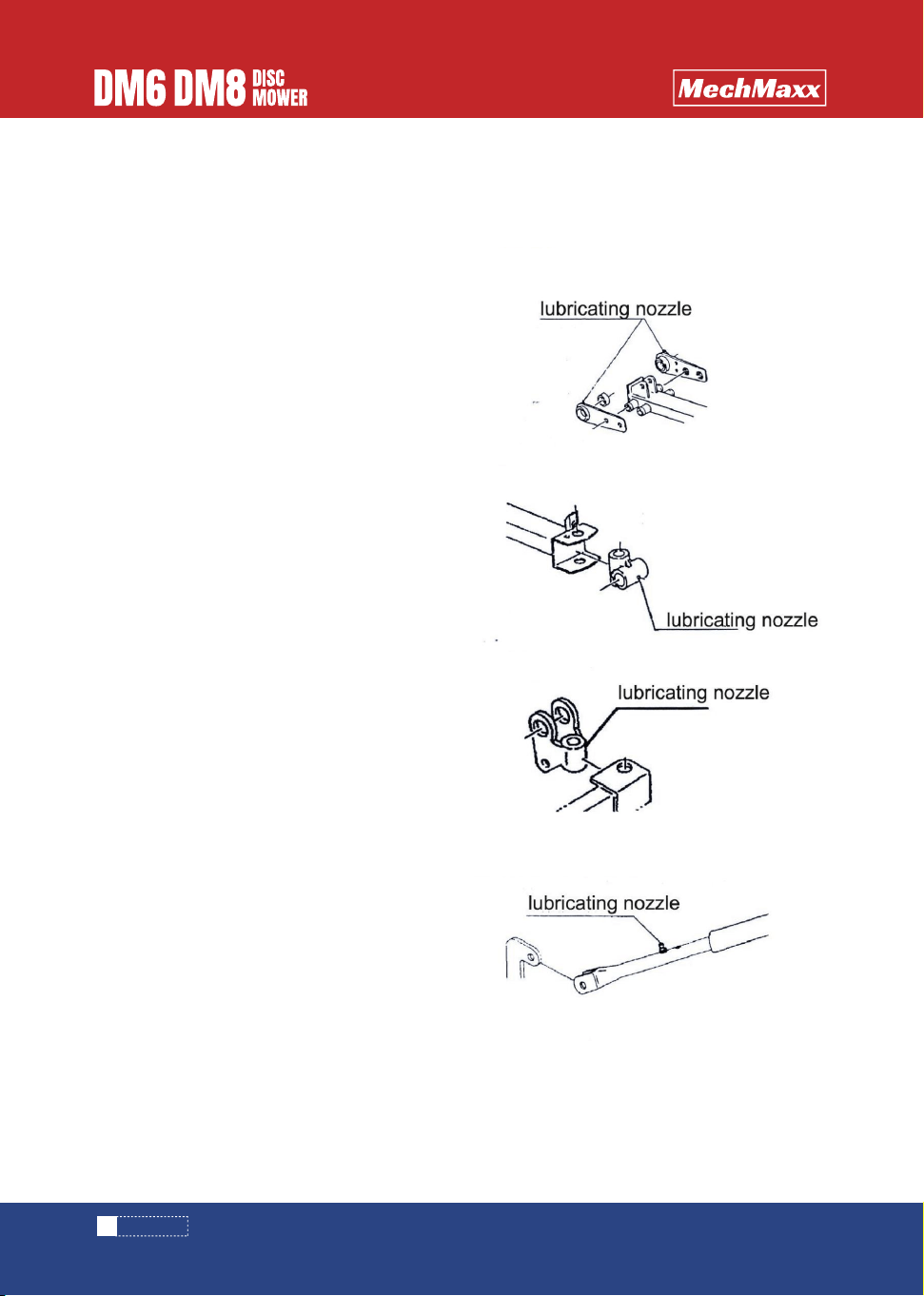
INSPECTION
1. Gear box
3. Pivot pin bush
4. Pivot shaft bush
2. Cutter bar
LUBRICATION SPOTS TABLE
In order to let the air out of the gear box, add oil slowly
when the oil nearby the oil filler.
Check the scale of oil to the oil filler after filling oil for 5
minutes.
Check oil in each 50 hours.
Apply fresh and clean oil and grease the machine.
Apply grease to a greae nipple until oil grease come out.
After finsihing production, every part was lubricated,
please check before using.
Replace oil at the first 50 hours or 30ha of new
machine, then replace all spots in each 50 hours.
Replace oil from every 300 hours or every season since
the second time.
When replacing oil, fold the discs firstly.
Replace oil at the first 50 hours or 30 ha.
Replace oil from every 300hours or every season since
the second time.
Oil filler is on the front part of the bottom cutter bar, oil
drain out is on the downside of disc bottom.
Use measuring cup to measure oil, and add oil in fix
quantity.
When add oil, the discs are in vertical (fold) states.
Please add lubricating oil when the cutter is folding.
5. Stand
6. Guide sleeve

15
www. mechmaxx.com
INSPECTION
7. Universal coupling
Gear box 0.4L
Oil fillerGear oil; SAE90
API GL-5
300 hours
or 1 season
1
Discs 1.7L (DM6)
2.4L (DM8) Lubricating
nozzle (DM6)
2
Safety bar
Grease: No.2 Every use
3
Pivot pin
bush
Lubriating nozzleProper Q'ty
4
Pivot bush
shaft
5
stand
Lifting
arm; B
Lubricating
nozzle (DM6)
Universal
coupling
Lubricating nozzle, paint
inner or outer wall
7
8
6
1
1
1
2
1
1
-
1
Lubrication
points
Point Kind of
lubrication
Changing
time
Q'ty RemarksNO.
CAUTION WHEN USING
Avoid adding oil to the safety bar of DM8.

16
www. mechmaxx.com
CAUTION
When lift discs, someone will be hurt if he is too
close to the discs.
OPERATION ATTENTION
Locking pin is in the lower hole, the body will not
suit the uneven ground and be damaged by
excessive force.
WORKING METHODS
WORKING METHODS
INSPECTION BEFORE OPERATION
BEFORE WORKING
WORKING TYPES
1. Disc mower is used for harvest forage in pasture,
please don't use it in other ways.
2. After rain, when it's too wet or in humidity areas,
please don't use it.
1. Cutting working.
When cutting working, keep horizontal position form
cutting bar.
2. Harvest operation in inclined surface.
Working in Inclined surface, such as dams, change the
mower from horizontal into up or down.
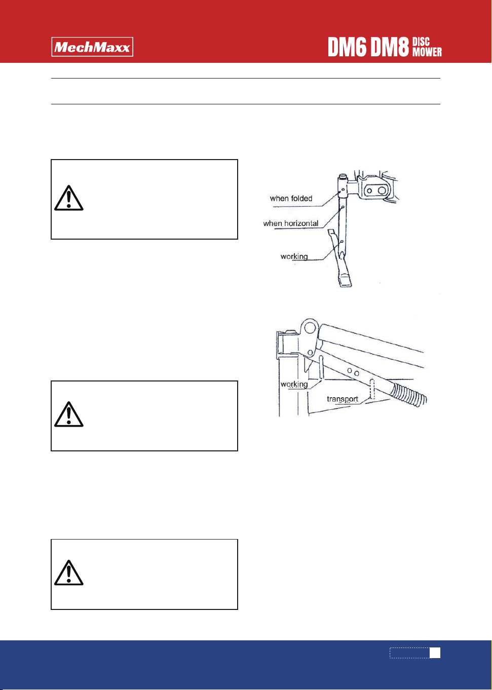
1. When it move, please fold arbor to moving position.
2. The change of working position.
(4) Stopper plate to the working position.
(5) Spread protection.
(1) When arriving pasture, please connect it with 3
point hitch, and adjust the plate to the working position.
Open the shut-off valve, operate hydraulic control level
of tractor, open discs.
(2) Adjust the cutter bar to the horizontal position from
behind.
(3) Adjust the locking pin to the hole in the top.
(2) on the inclined surface,such as dams,cutting plate
change from horizontal to be above 30º and working
towards lower place, the spring should be 50-100mm
longer than the above standard.
Tight the locknut after adjusting.
4.How to adjust collecting bar.
Adjusting the collection bar according to grass situation
by three parts.
Adjust by grass pasture density,use the top hole when
large quantity.
4.Adjust to the minimum of collecting plate
Adjusting the minimum of collecting plate by bolts
M10*40
Adjusting by grass collecting condition.
Put the collecting plate lower when there are missing
grass, then tight the locknut.
6.Adjusting protecting device
When working in the pasture with rocks and uneven
ground,to prevent soil and stones being splashed,please
adjusting the protecting device from top to bottom.
1. Adjust the height H of the lower connecting pin from
the ground.
(1) When working, the height of lower connecting pin is
according to the below standard by adjusting the point
hitch.
Height for the hitch 520mm (H)
(2) Cutting in inclined surface, put the discs plate in the
inclined surface first, adjust the height of lower
connecting pin to make the disc plate match with the
inclined surface.
2. Adjusting the cutting height
Adjusting the cutting height by top link.
Make it lower by shorten top link, higher by elongate top
link.
Usually the cutter Arbor anteversion angle is 3-4°.
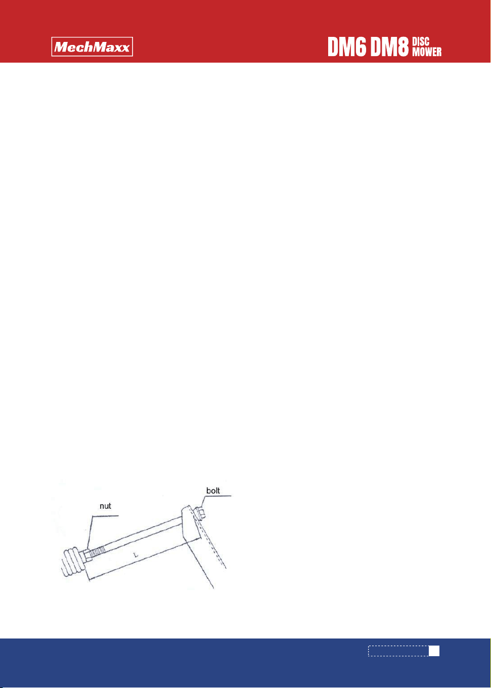
3. Adjusting spring on adjusting bar
(1)lt's easy to adjust the cutter folding situation by
adjusting bolts.
standard installing size L as below
Please tight the locknut after adjusting.
L=270mm
17
www. mechmaxx.com
WORKING METHODS
ADJUSTING WHEN WORKING

18
www. mechmaxx.com
1.Cutting
When connecting PTO, keep the engine of tractor in low
speed and connecting slowly.
(1)the standard rotary speed is 540-600 rpm, please
keep this speed.
Operation precautions
If the locking pin is in the underside hole, mower will not
suit to the uneven ground, and the mower will be
damaged by excessive force.
When running a tractor with a clutch on PTO, keep 3-5m
Run-up distance, and work after the PTO is running in
standard speed.
(2) working speed is 6-10km/h, choose speed accord-
ing to the situation.
(3) Working according to the shape of pasture.
Usually from the left to the right, at last, the outermost
is from the right to the left.
The rotary way in the corner has 3 ways as showing in
the following picture.
According to your driving level to choose.
Turn around at the corner
OPERATING MAIN POINTS
DANGER
When working or turning,touching discs will be
hurt. Besides, stones splashing from discs will
also hurt someone.
Keep away from people around.
Don’t operate while the safety cover was open.
WARNING
When working, somebody will be rolled in and
cause heavy casualties if somebody is close to
the mowers. Keep away from people around by.
If the PTO rotation speed is more than the point-
ed speed, the mower will be damaged and cause
accident. Obey the pointed PTO speed.
Keep low speed when working in inclined
ground.
Pay attention to the front and around.
CAUTION
When lifting the discs up and down, if someone
close to the mower,someone will be hurt. Keep
people away from the mower.
If put hands to the open position of cover,hands
will be rolled in the rotary position and get hurt.
Please don’t put hands into the cover.
When adjusting or checking the machine,stop
PTO and the engine, and make sure the rotary
and movable position completely stop.
WORKING METHODS

Direct cycle
Turn back to change direction
(5) When you cut in the periphery of pasture, operate in
low speed, pay attention to the uneven ground and
obstacles.
(6) If there are unusual vibration and sound during work-
ing:
1.stop working at once, stop PTO, and stop engine
2.check the reason after completely stop rotary and
movable position, work again after problem solved.
If safety device works while working:
1.stop working at once, retreat tractor, restore safe
device, stop PTO, stop engine.
2.check the reason after completely stop rotary and
movable position, work again after problem solved.
2.cutting in inclined ground
When cutting in inclined ground, please working as the
following procedures:
Lift the tractor 3 point hitch vertically, choose the upper
linkage hole on the 3P frame.
Adjust the proofreading chain, make the mower shift to
the right( look from the back side).
Make the mower towards adown. Adjust the distance of
bottom connecting pin and the ground, to make the
discs matched with inclined ground.
The discs inclined angle different from the height of
bottom linking pin to the ground.
The angle of cutter bar Max 30-40º underneath horizon-
tally.
(4) rotation in peripheral of pasture.
1.lift 3 point hitch
2.equipped with hydraulic device, operate the external
hydraulic control level, rise the discs horizontally.
According to the function of stopper plate, the discs
cannot be lift at the right position.
Operation precautions
Don’t excessively rise the machine
Operation precautions
If you keep working while safety device starts, the
working quality will be bad and mower will be damaged.
Operation precautions
When turn in the ridge, and fold the discs vertically, if
the disc is spinning, It will be very dangerous to close
the tractor.besides, the protection device will be
damaged if it hits the tractor cab.
Please don’t fold the discs vertically.
The position of the lifting discs, just keep away the
grasses.
19
www. mechmaxx.com
WORKING METHODS

20
www. mechmaxx.com
1. Lift the 3 point linkage, rise the mower, the support
pin insert to the following hole.
If fold the mower without folding the protect cover to
the rear, the safety cover will be damaged.
Fold the protect cover first, then fold the discs plate.
4. folding discs
If the machine have hydraulic device, use the tractor
hydraulic joystick to fold discs plate, and stop stop
valve, then fix main frame and lift frame by pin.
5. Move after confirming the tractor 3 Point linkage was
prevented from decline.
2. Folding the first half of protect cover to the rear.
3. Put the stopper plate to the transport position.
Attention in use
TRANSPORT
CAUTION
When cutting in inclined ground,if the discs are
too close to the ground, the tractor’ s sideslip
and lateral turnover, will cause unexpected
accident.
Do not too close to the inclined ground and
lower working speed.
WARNING
Please fold knife arbor before mowing the
machine.
If not,touching obstacle will cause accident.
Attention
Some body will be involved in and cause injuiry if
the machine is still working.
Stop PTO before moving.
WORKING METHODS
In order to extend service life, please operate as follow-
ing.
1. Remove grass on the mower,especially in rotary
parts, seals, and bearings.
2. Check whether there are missing, lossing and
damaged bolts, nuts, pins. fix the nuts or replace the
parts if there is abnormal.
3. Blades are easy worning parts, prepare substitute
parts in advace.
4. The exposed positions without painting such as PTO
shaft, PIC shaft, and couplings, paint Lubricating oil to
prevent rusting.
(2)The discs in folded position
1.Pillar installing position. Fix at the hole bayonet lock
pin from the above position.
2.Suspension device pin. Insert to the moving position.
3. Turn off the stop valve and get rid of the pressure in
the quick connector before take off the quick connector
from tractor hydraulic output.
Tie up hydraulic soft tubes and hang on the 3P frame.
Operation precaution
While remove the quick connector from tractor hydraulic
output with stop valve open, it will be difficult to
connect the next time, because there is pressure in the
quick connector
Act after turn off the stop valve, remove the pressure in
quick connector.
4.after remove from tractor, keep Universal coupling in
the hook of 3P frame.
1.Operate in opposite direction with [1 to the tractor
connection].
2.Detach and store with tractor
(1) discs in horizontal
1.Pillar mounting position. Fix at the middle hole by pin.
2.The pin of hitch device. insert to the working position.
ARRANGEMENT AFTER WORKING
DETACH WITH TRACTOR
www. mechmaxx.com
21
CAUTION
If cleaning adhesion objects in rotary parts or
movable parts without cutting off power, some-
one will be involved and get hurt.
Cut off PTO, stop engine,make sure rotary parts
and movable parts were stopped.
CAUTION
When detaching tractor and mower in inclined
ground or uneven ground or soft ground,tractor
move suddenly will cause accident.
Please detach on even and hard ground.
CAUTION
If store the disc mower with discs vertically, the
turn-over discs will cause injury.
Please store the machine with discs horizontal-
ly
AFTER WORK
AFTER WORK

1.clean all parts of mowers
2.Replace the consumed and damaged parts in time.
3.Add oil according to[Page 14].
Apply oil to rotating, pivoting parts and sliding parts
such as clump pin of power joint.
Apply grease on PTO shaft, PIC shaft and spline holes of
power joint yole.
4.release V-belt.
5. Paint or apply oil on damaged surface of parts to
prevent from the rust.
6.Store the machine in well ventilating indoor.
7.If there is no choice but to keep the machine in out
dorr, cover the machine with a plastic sheet.
Precaution in use
8.If there is no choice but to keep the machine in out
dorr, cover the machine with a plastic sheet.
Precaution in use
Fold discs plate for storage,please do it in flat and hard
ground.
Besides, take method to prevent it being turn-over.
22
www. mechmaxx.com
CAUTION
If store the disc mower with discs vertically, the
turn-over discs will cause injury.
Please store the machine with discs horizontal-
ly
AFTER WORK
Inspection and maintenance should be done regualrly to obtain good condition.
Inspoect and maintain each parts in accordance with inspection and maintenance table to prevent from accident by
poor maintenance.
remedy
After initial 1
hour
After initial
2-3 hour
After initial
50 hour or
30ha
Before
operation
After
operation
Out of
season
Looseness of all bolts and nuts
V-belts tightness
Gear box oil Disc plate oil
Cleaning up
Wearing of blades
Looseness of bolts and nylon-nuts
Looseness of nylon-nuts on the discs
Oil spill of gear box and discs plate
V-belts tightness
Oil leaking of oil pressure system
Spring size of safety device
Looseness of bolts and nuts and pins
Drive device noisy, abnormal
vibration,abnormal heat
Damage of coupling,cover, and chain
Refuel in rotary parts and movable parts.
Gear box oil/Discs plate oil
Broken part
Wearing parts such as blades
Cleaning up each parts
Damage of painting
Worn pivoting parts or pins
tighting
According to [Page 24 V-belts tightness adjustment]
According to [Page 14 refuel list] change
According to[Page 24 blades change
Tight,if worn,please change
Tighting
Change sealing parts
In accordance [Page 24 V-belts tightness ]
Amend from the end, tihgting or amending
According to [Page 24 adjust safety device]
Tighting or change parts
According to [Page 26 adverse treatment list]
Replace
According to [Page 14 refuel list] change oil
According to [Page 14 refuel list] change oil
Fix or change
Change as soon as possible
Printing or applying oil
Replacement to new ones
Items for checkinghours
INSPECTION AND MAINTENANCE TABLE
www. mechmaxx.com
23
CAUTION
● Lock th hydraulic circuit of tractor when the machine is lifted up for maintenance or inspection tp prevent the
machine being fall down.
● Inspection or maintenance should be done on solid ground or concrete. Never inspect of main on slant, uneven,
or soft ground.
● Stop PTO and engine and make sure the rotaryand movable parts are stopped. If inspect the rotary and
movable parts without stop the engine, people will be rolled in and cause accident.
●If hydraulic connector and soft tubes is slack or damaged,high pressure oil spray, and mower decline quickly,
someone will be hurt.please repair and change parts. Please release the pressure in hydraulic tubes, then remove
hydraulic connector and soft tubes.
● Please put the covers to the original position after inspection and maintenance. if not, someone will get rolled
in the rotary and movable parts and cause accident.
INSPECTION AND MAINTENANCE
INSPECTION AND MAINTENANCE

1.safety device adjustment
Safety device will protect the mower if it hits obstacles
while working.
Spring size of safety device, H=144mm
When it’ s available, roll in 1-2mm according to the
pasture situation.
If the spring is too tight, when the mower hit obstacles,
the spring will not work. and the mower will be
damaged.
Don’t press spring too tight.
2.V-belts tightness adjustment
After working a while,V-belts will be loose, please
adjust it according to the following:
3. change blades
(1)every disc has two blades.
If worn, please replace or sharpen as soon as possible.
Please keep nylon screw clean, fix discs in angle mate-
rial, loose nylon screw.
Tight screws and nuts of blades, make discs reasonable
fix.
Tightening torque to 110~127N*m,and fix.
If nuts, bolts and washer of loaded knife is worn, please
change in time.
4.change discs
When replace discs, please keep 90 degrees with the
next disc’s knives.
Align splines and gears.
Because of new machine, please adjust V-belts after
using 2-3 hours.
If we don’ t care to adjust tight of belts, the number of
rotary of discs can’ t be guaranteed, and effect the
cutting results, and the life of belts will be shorter.
Please keep the tightness of V-belts.
Replace a set of complete belts.
(1)loose four bolts and nuts
(2)Remove the cover of inspection hole, adjust by
tensioning bolt.
(3)When we put 3.7kgs weight in the middle of
belts,the belts sag 16mm. it show the tightness of
V-belts is right.
(4)After adjustment,fix the bolts and nuts again.
Precaution in use
Precaution in use
The blades may impact each other if the disc are not in
90 degrees with the next disc’ knives.
Please install knives correctly.
Install bolts M12x15,clip in angle material when unload,
install the discs, to preserve discs move. Tight M12*25
in 110~127N*m(=1,100~1,270kg*cm) tightening
torque.
Precaution in use
The blade can rotate left and right. Confirm the rotating
direction first, then change it.
Precaution in use
ALL PARTS ADJUSTMENT
24
www. mechmaxx.com
INSPECTION AND MAINTENANCE
Adjust the machine in accordance with trouble shooting table if it does not work well.
remedy
Disc Plate
(cutter bar)
Abnormal noise
bolts of blades is loose
Nuts of discs is loose
Oil quantity is not suitable
Gears or bearings damaged
The supporter pins of hitch device
is in transporting position
The height of bottom connector
pin is not suitable
Installation length of adjustment
spring is not suitable
PTO rotary speed is too low.
Working speed is too fast Working
way is wrong Blades cutting is bad
Blades is damaged Blades is worn
Install different rotary direction
blades There is soil or grass in
on covers
Adjust PTO rotary speed to
540-600 rmp Reduce working
speed According to [Page 16
working way] to deal with
According to [Page 24 changing
blades] to deal with
Please clean attached grass
Put the supporter pins of hitch
device in the working position.
According to [Page 17] adjust the
height of the bottom connector
pin According to [Page 17] adjust the
height of adjustment lever spring.
Tight Change oil according to
[Page 14 refuel list] Change parts
Abnormal heat
Can’t match with ground during
working
Cutting traces mess
Fault Possible cause Name
TROUBLE SHOOTING TABLE
www. mechmaxx.com
25
CAUTION
1.Lock the hydraulic circuit of tractor when the machine is lifted up for maintenance or inspeciton to
prevent from machine’s falling down.
2.Inspection or maintenance should be done on solid ground or concrete. Never inspect or maintain on
slant, uneven, or soft ground.
3.Stop the tractor engine, disengage PTO and make sure all moving parts stop when inspection or
adjustment is done.
4. When someone remove covers to inspect,someone will be involved and get hurt if the covers haven’t
been installed well. Please install all unloading parts well.
TROUBLE SHOOTING
TROUBLE SHOOTING

If you don’ t know the reason or how to dealing with it, please write the following content and contact with dealer in
local market.
1.commodity
2.Parts supplied form
3.Manufactured number
4.Fault ( as detailed as possible)
remedy
Disc Plate
(cutter bar)
Gear box
V- belts
Safe device
Block grass
cover
Hydraulic
system
Universal
coupling
No traces
Abnormal heat
Abnormal noise
Abnormal heat
During working, movable
Be blocked by mown grass
Could not lift the discs plate
Abnormal noise
One-way clutch malfunction
Discs plate could not be fold in
right angle
Discs rotary slowly
V-belts slip
V-belts slip Safety device works
Working speed is too slow
PTO rotary speed not suitable
Supporter pin of hitch device is
not in working position
Oil is unfit
Gear,anxle,bear is damaged
V-belts tightness is unfit
Pasture grass is too much
Spring length of Safe device is
unfit. Pasture is not smooth
Working speed is too slow
Throttle to adjusting speed is
completely closed
Stopper plate in working position
No oil Angle is too large
No oil
One-way clutch is damaged
Put the supporter pin of hitch
device in moving position.
According to [Page 14 refuel list]
change oil Replace parts
According to [Page 24 V-belts
Tightness adjustment]
Reduce working speed
According to [Page 24 safe
device adjustment]
Reduce working speed
Speed up working speed
Adjust the throttle to more open
Put stopper plate in movable
position
Spread oil in safe cover,tubes
(inside and outside) overlapping
portion Lift 3 point hitch to
standard position
Spread oil Replace parts
Improve working speed
Adjust PTO rotary speed in
540~560 rpm
According to [Page 24 V belts
tightness adjustment
Safety device reset
Grass disordered
Discs plate couldn’t be fold in
right angle
Fault Possible cause Name
26
www. mechmaxx.com
TROUBLE SHOOTING

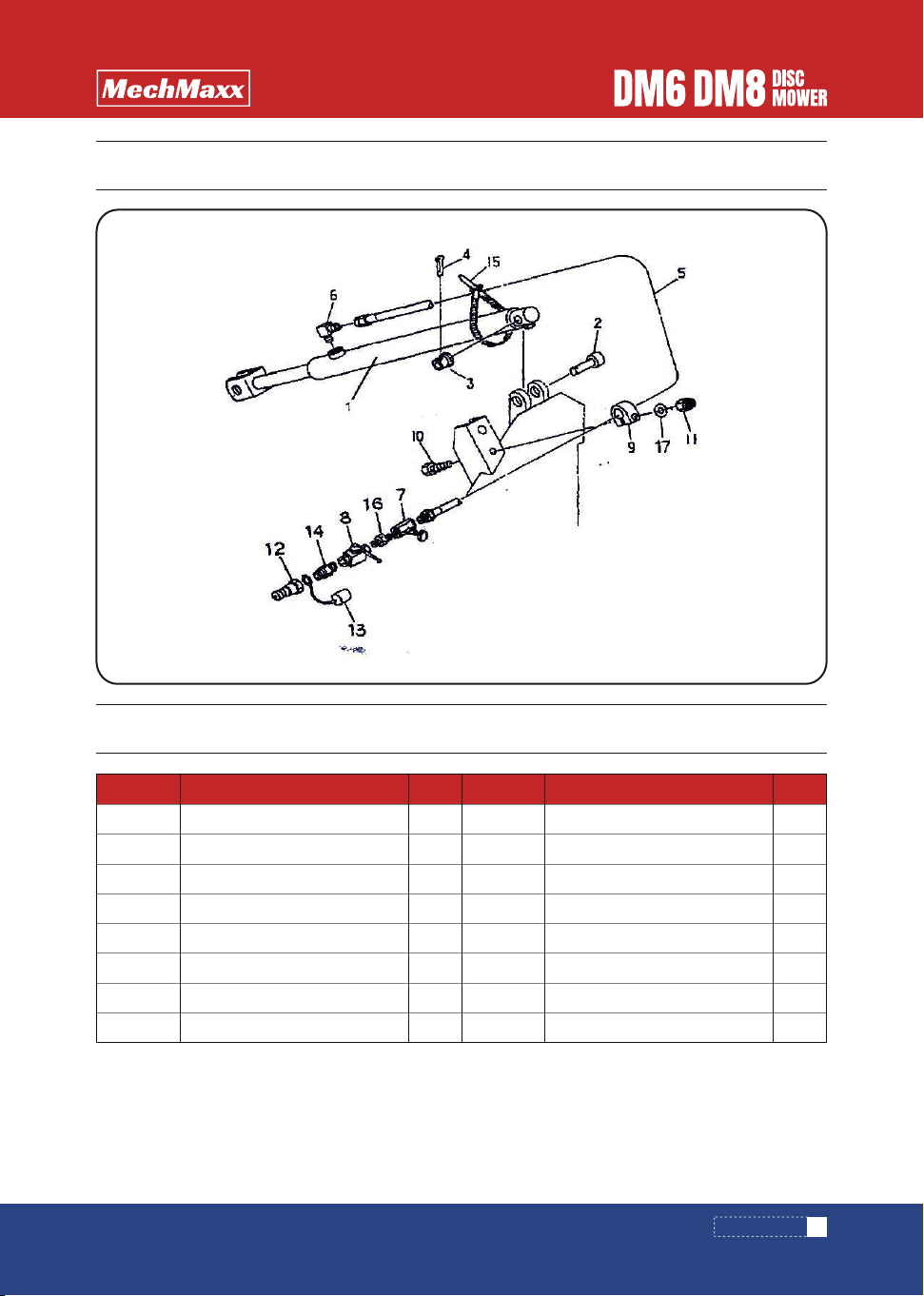
PARTS DIAGRAM(FRAME SUSPENSION ASS)
www. mechmaxx.com
27
PARTS DIAGRAM

PARTS LIST(FRAME SUSPENSION ASS)
QTYQTY
1
2
3
4
5
6
7
9
10
11
12
13
14
15
16
18
19
20
21
22
23
24
25
26
27
28
29
30
31
32
33
3PT frame
Upper connecting pin
B pin: 19x3
sleeve
Grease nipple A M6x1
Pin CP: F40x135
Bolt M12x25 8.8
Bolt M10x20 8.8
Support CP
Cap 28.6
Bayonet lock 9
Main frame CP
Sleeve F
Sleeve RE
Bush 100x34
Pin 16
Bolt M16x35 8.8
Bolt M16x35 8.8
Lower connecting pin
Nut M24x1.5 8
Annular pin 9
Seat CP
Conneting rod CP
Spring H10x53x500
Rod head CP
Cylindrical pin 6x40
Cylindrical pin 10x40
Pin 16x60
Cotter pin 3.2x32
Pin
Annular pin 9
1
1
1
1
3
1
1
1
1
1
2
1
1
1
2
1
2
2
2
2
4
1
1
1
1
1
1
1
1
1
1
1
1
1
2
1
1
1
1
1
1
1
1
1
11
1
4
2
1
Pin 20x104
Pin CP
Cotter pin 5x36
Disc spring
Nylon locking nut M16
Stop plate
Pin CP
Washer 20
Nylon locking nut M20
Washer 16
Label: operating
Label :540-600rpm
Data plate
Spring washer 12
Spring washer 10
Spring washer16
Spring washer 24
Support CP
PART DESCRIPTION PART DESCRIPTIONPART NO. PART NO.
34
37
38
39
40
41
42
43
44
45
46
47
48
49
50
51
52
53
28
www. mechmaxx.com
PARTS LIST

www. mechmaxx.com
29
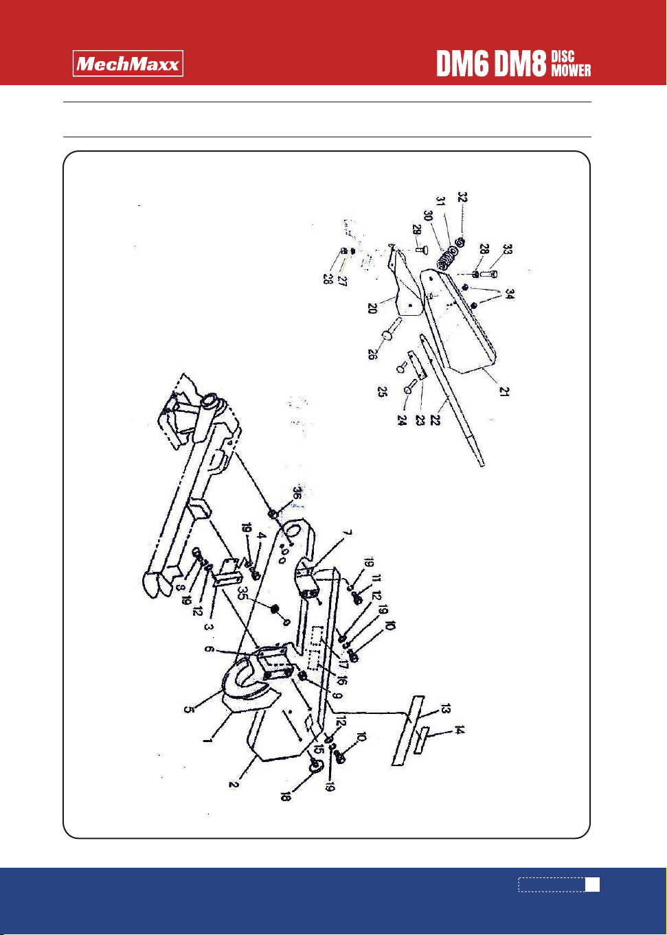
PARTS DIAGRAM
PARTS DIAGRAM(SAFETY ASS)

30
www. mechmaxx.com
PARTS LIST(SAFETY ASS)
QTYQTY
21
22
23
24
25
26
27
28
29
30
31
32
41
42
43
44
45
46
47
48
49
50
51
52
53
54
55
57
58
60
61
Safe bar CP
Pin 20
Positioning plate
Double head safety bolt
Spring A10x38x150
Spring seat
Nylon locking nut M16
Rod CP
sleeve
Bolt M16x35
Pin 20x72
Cotter pin 5x36
Pin CP: B
Bracket
Bolt M10x20 8.8
Grease nipple A M6
Lifting support CP
Hexagon socket screw M16x40
Pin 20x65
Cotter pin 5x36
Spring seat: 51
Bolt CP: M16x600
Nut M16
Spheric washer :16
Washer: 16
Elastic cylindrical pin 10x32
Pin 20x55
Bolt M12x30 8.8
washer
Rod: 180
Spring :H14x68x756
1
1
1
1
1
2
1
1
1
1
1
2
1
1
1
1
1
4
1
4
1
1
1
1
1
1
1
1
1
2
1
1
1
1
1
1
Seat : CP
Pin :20x55
Spring washer 12
Spring washer 16
Spring washer 10
PART DESCRIPTION PART DESCRIPTIONPART NO. PART NO.
62
63
64
66
67
PARTS LIST
www. mechmaxx.com
31
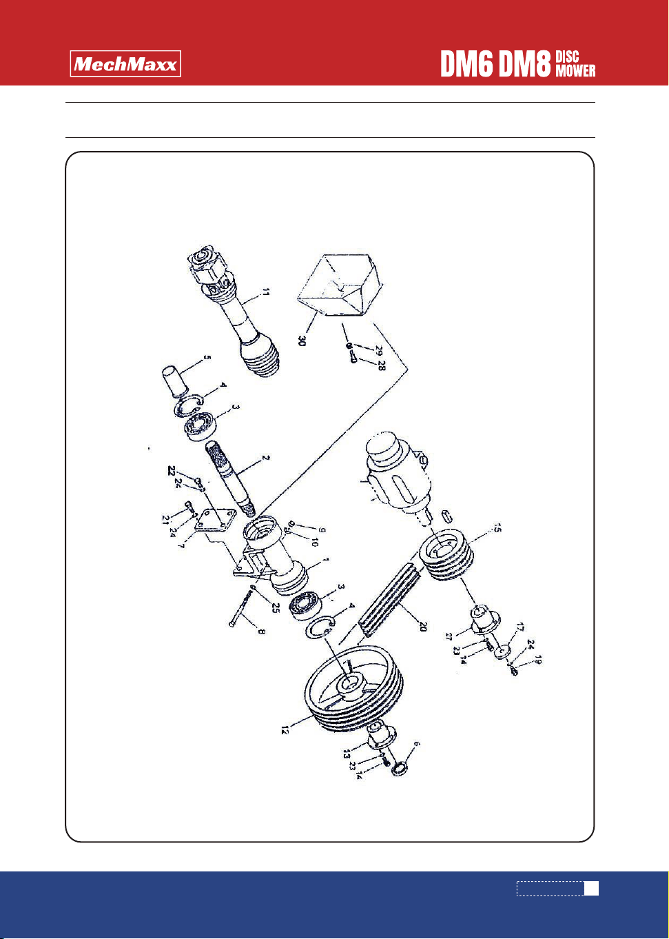
PARTS DIAGRAM
PARTS DIAGRAM(TRANSMISSION MECHANISM)

32
www. mechmaxx.com
PARTS LIST(TRANSMISSION MECHANISM)
QTY
1
2
3
4
5
6
7
8
9
10
11
12
13
14
15
17
19
20
21
22
23
24
25
27
28
29
30
Bracket
PIC input shaft
Bearing
Cirelip 72
Shaft sleeve
Caulking nut M30x1.5
Steel plate
Bolt
Hex Nut M12 (8)
Four hexagon nut M12
Universal coupling
V belt pulley 305B-4
Liner bushing: A
Bolt M10x30 8.8
V belt pulley: 165B-4
Washer 13x6
Bolt M12x30 8.8
V belt B-104
Hex bolt M12x190
Bolt M12x100 8.8
Spring Washer 10
Spring Washer 12
Washer 12
Liner bushing B
Bolt M8x20
Nut M8
PIC cover CP
1
1
2
2
1
1
1
1
1
1
1
1
1
8
1
1
1
4
2
2
8
5
1
1
2
2
1
PART DESCRIPTIONPART NO.
PARTS LIST
www. mechmaxx.com
33
PARTS DIAGRAM
PARTS DIAGRAM(GUARD PLATE)

34
www. mechmaxx.com
PARTS LIST(GUARD PLATE)
QTYQTY
1
2
3
4
5
6
7
8
9
10
11
12
16
17
18
19
20
21
22
23
24
25
26
27
28
29
30
31
32
33
34
Pulley cover: F
Pulley cover CP: RE
Support plate CP
Bolt M10x20
Cover
Support plate CP
Support plate CP
Bolt M10x25
Nut M10
Bolt M10x20
Bolt M10x40
Washer 10
Label :waring
Label: waring
Minror
Spring washer 10
Support connecting plate CP:R
Guard plate CP: R
Guard rod
Guard rod seat
Bolt M8
Bolt M8
Bolt M12x85
Spring washer 10
Hex nut M10
Bolt M10x30
Compression spring 6x25x48
Washer 12
Nylon locknut M12
Bolt M10x40 8.8
Nylon locknut M8
1
1
1
2
1
1
1
2
2
4
2
6
2
1
1
1
1
1
1
1
1
1
1
3
3
3
1
1
1
1
2
1
2
Seal cap
Bush
PART DESCRIPTION PART DESCRIPTIONPART NO. PART NO.
35
36
PARTS LIST
www. mechmaxx.com
35
PARTS DIAGRAM
PARTS DIAGRAM(ADJUSTMENT LEVER)
PARTS LIST(ADJUSTMENT LEVER)
QTYQTY
1
2
3
4
5
6
7
8
1
1
1
1
1
1
1
1
Hydraulic cylinder
Pin
Bush
Cotter pin 5x56
Hose CPG1/4x
Elbow PF1/4-PT1/4
Throttle valve Rc1/4
Stope valve Rc1/4
Pipe clamp
Bolt M8x50
Nylon locknut: M8
Quick coupling
Join PT1/4-1/8
Plastic buckle 7.5x382
Join PT1/4
Washer M8
1
1
1
1
1
1
1
1
PART DESCRIPTION PART DESCRIPTIONPART NO. PART NO.
9
10
11
12
13
14
15
16
36
www. mechmaxx.com
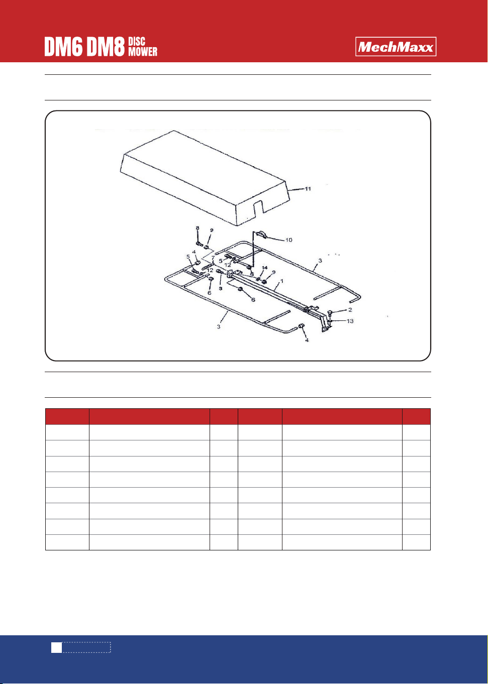
PARTS DIAGRAM
PARTS DIAGRAM(PROTECTOR ASS)
PARTS LIST(PROTECTOR ASS)
QTYQTY
1
2
3
4
5
6
7
8
2
1
1
4
4
1
Protector bracket CP
Bolt M12x30 8.8
Protector CP
Handle 24
Bolt M10x50
Nylon locknut
Spring 4x125
Bolt M10x60
Nut M10 8.8
Bayonet lock
Protector cover
Washer 10
Spring washer 12
Spring washer 10
1
4
2
2
4
6
1
3
PART DESCRIPTION PART DESCRIPTIONPART NO. PART NO.
9
10
11
12
13
14

PARTS DIAGRAM(CUTTER BAR ASS)
www. mechmaxx.com
37
PARTS DIAGRAM

PARTS LIST(CUTTER BAR ASS)
QTYQTY
1
2
3
4
5
6
7
8
9
10
11
12
13
14
15
16
17
18
19
20
21
22
23
24
25
26
27
28
29
30
31
1
1
1
Side disc caps
Side discs CP
Middle disc cups
Middle discs CP
Blades L
Bolt
Nylon locknut M12
Washer
Blades R
Hex blot M8x20
Spring washer 8
Hex bolt M12x25
Spring washer 12
Support positioning plate
Square neck bolt M10x35
Nylon locknut M10
Guard plate CP
Lower guard plate
Square neck bolt M10x25
Nylon locknut M10
Square neck bolt M10x35
Flat gasket 10
Connecting plate CP
Bracket bottom board CP
Hex bolt M12x75
Hex bolt M12x55
Rod B
Rod A
Hex bolt M12
Folded plate
Hex bolt M12x20
1
2
4
4
6
12
24
12
6
8
8
24
36
1
3
3
6
6
10
12
1
1
1
1
8
2
2
1
10
1
2
Steel plate
Bush
Bolt M10x60
PART DESCRIPTION PART DESCRIPTIONPART NO. PART NO.
32
33
34
38
www. mechmaxx.com
PARTS LIST

www. mechmaxx.com
39
PARTS DIAGRAM
PARTS DIAGRAM(DISCS)

40
www. mechmaxx.com
PARTS LIST
PARTS LIST(DISCS)
QTYQTY
1
2
3
4
5
6
7
8
9
10
11
12
13
14
15
16
17
18
19
20
22
23
24
25
26
27
28
29
30
31
Upper gearbox cover CP
Seal bar
Lower gearbox cover CP
Oil Plug 1/4"
Connecting plate CP2
Connecting plate CP1
Reinforcing bar
Circlip 80
Circlip 40
Deep groove ball bearing 6208
Gear 39T
Hex bolt M14x35 8.8
Flat gasket 14
Washer 2.7
Bearing 16009
Gear 31T
Circlip 75
Gasket ring
Gear 38T
Disc shaft
Deep groove ball bearing 6207-2RS
Disc sleeve
O seal ring G35
Inner Oil seal ring
Oil seal 45x60x7
Deep groove ball bearing 6307
Gear 30T
Hex nut M27
O seal ring G110
Bolt connecting parts CP (large)
Bolt connecting parts CP (small)
Hex nut M12
Spring washer 12
O seal ring P11
Hex bolt M10x30
Hex locking bolt M10x20
Hex locknut M10
O seal ring G100
Spring washer 14
1
1
1
2
1
5
1
1
1
1
1
12
12
36
24
2
12
12
10
6
6
6
6
6
6
6
6
6
6
6
6
24
24
26
18
17
24
1
12
PART DESCRIPTION PART DESCRIPTIONPART NO. PART NO.
32
33
34
35
36
37
38
39
40
www. mechmaxx.com
41
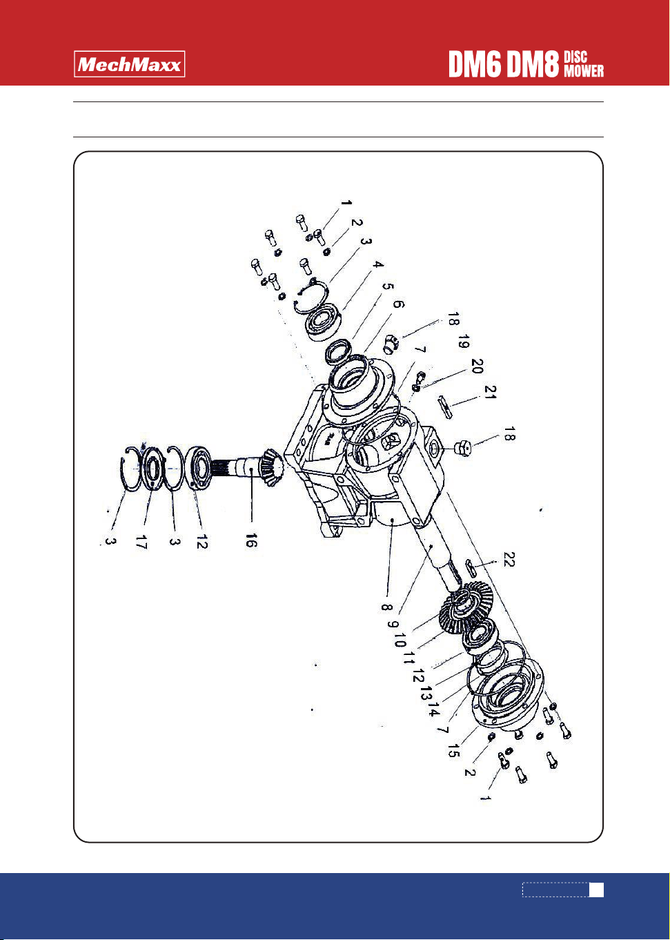
PARTS DIAGRAM
PARTS DIAGRAM(GEARBOX)

PARTS LIST
42
www. mechmaxx.com
PARTS LIST(GEARBOX)
QTY
1
2
3
4
5
6
7
8
9
10
11
12
15
16
17
18
19
20
21
22
Hex bolt M10x25
Spring washer 10
Circlip 80
Deep groove ball bearing
Seal 42x62x10
Gearbox cover A
O seal ring G135
Gearbox
shaft
Wedge
Bevel gear 33T
Deep groove ball bearing
Gearbox cover B
Bevel gear shaft 16T
Seal 35x80x10
Bolt AS
Bolt M10
Washer
Flat key 10x8x50
Flat key 10x8x35
12
12
3
1
1
1
2
1
1
2
1
2
1
1
1
2
1
1
1
1
PART DESCRIPTIONPART NO.