Operator’s Manual
www.mechmaxx.com
WARRANTY


TABLE OF CONTENTS
ASSEMBLE
ATTACHING TO A TRACTOR
ATTACHING TO A TRACTOR
2
2
6
7
12
INSPECTION BEFORE OPERATION
14
LUBRICATION SPOTS TABLE
16
OPERATION METHOD
19
OUT OF SEASON FOR STORAGE
20
INSPECTION AND MAINTENANCE
NAME OF FUNCTION
APPLICABLE TRACTOR SIZE
1
www.mechmaxx.com
5
TROUBLE SHOOTING
24
PARTS LIST
28
PARTS DIAGRAM
29
24
TROUBLE SHOOTING TABLE
28
HOW TO ORDER PARTS
28
SUPPLY TIME(PERIOD) OF SPARE PARTS
6
TRACTOR OPERATION SAFETY
IMPLEMENT OPERATION SAFETY
6
9
ATTCHMENT OF UNIVERSAL JOINT
12
INSPECTION BEFORE OPERATION
INSPECTION IN TRACTOR ENGINE RUNNING
12
16
PURPOSE OF THIS MACHINE
ADJUSTMENT FOR OPERATION
16
OPERATION METHOD IN FIELD
17
TRANSPORTATION
18
MAINTENANCE AFTER OPERATION
19
DETACHING FROM TRACTOR
19
STORAGE IN OUT OF SEASON
19
ADJUSTMENT FOR EACH PARTS
21
TABLE OF CONTENTS
2
www.mechmaxx.com
ATTACHING TO A TRACTOR
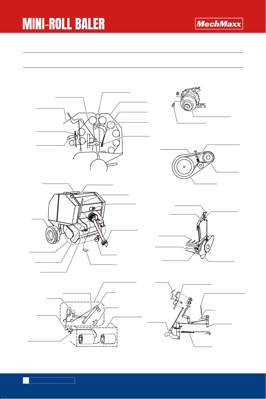
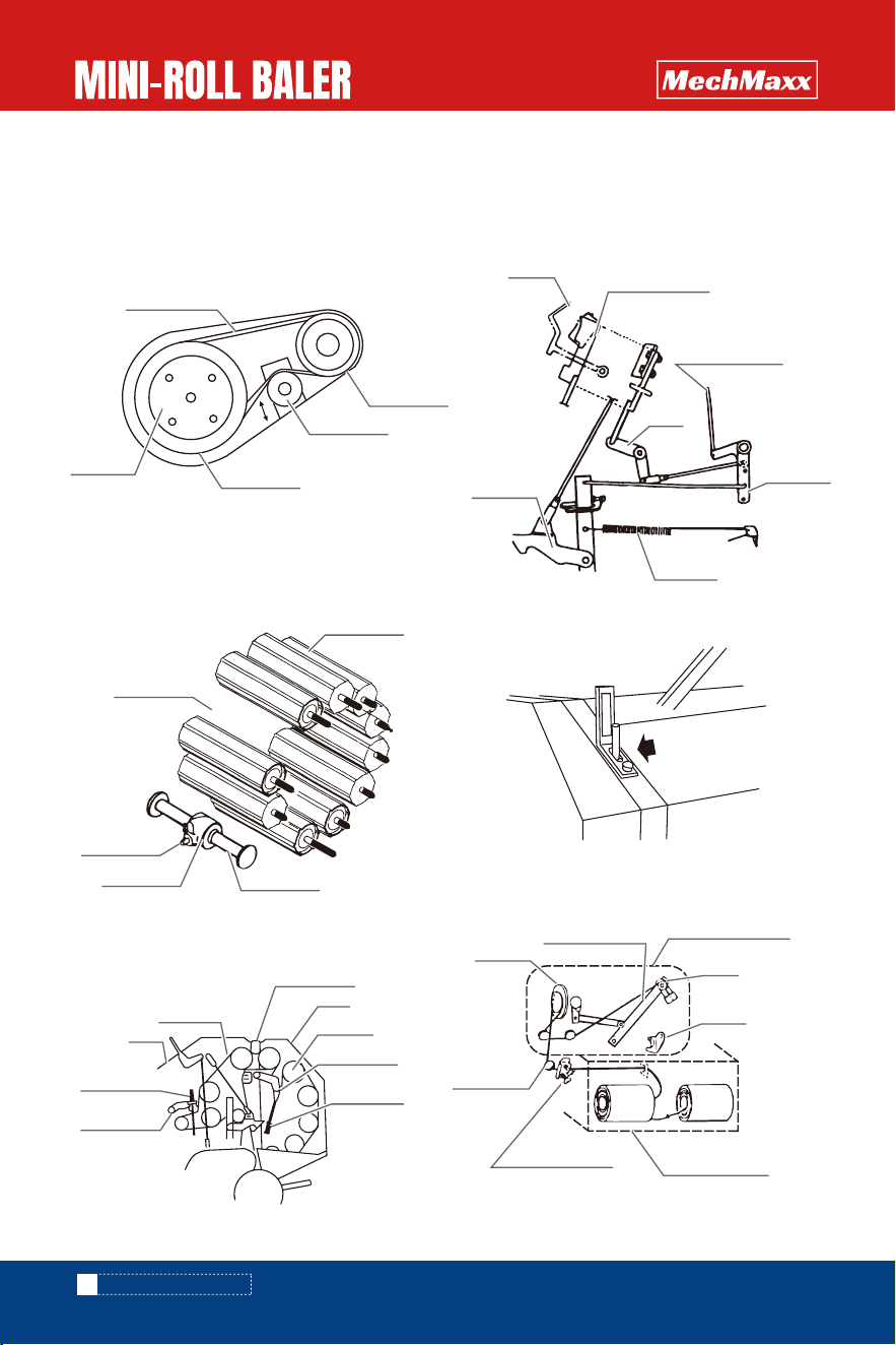
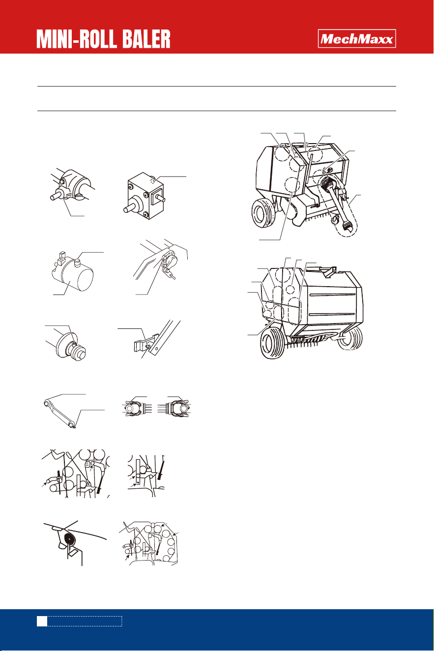
NAME OF FUNCTION
ATTACHING TO A TRACTOR
Tension Spring
Tension arm;B
Sprocket
Gate
Tension plate
Roller chain
Frame
Tension Spring
Tension arm;A
Tension Spring
Sprocket
Sprocket
Roller chain
Shear bolt holder
Shear bolt
Cylinder
Tire
Pick-up
Arm
Low link pin
Pivot Pipe
Lever
Top Link clevis
Universal joint
Stand
Buzzer
Bolt (lower limit)
Chain (lower limit)
Side cover
Tine
Cover shield
Crop cover
Lever
Latch
Stopper
Control lever
Rod (Indicator rod)
Rod
Bracket
Spring
Knife
Twine casing
Arm
Binding device
Twine
Guide roll
Twine Tensioner
Binding arm
Shear bolt
shear bolt is sheared when overload affect to the
machine for preventing from the damaged of the
machine.
Pick up assay
Pick-up assay is operated to pick-up baling Material
from the ground.
3
www.mechmaxx.com
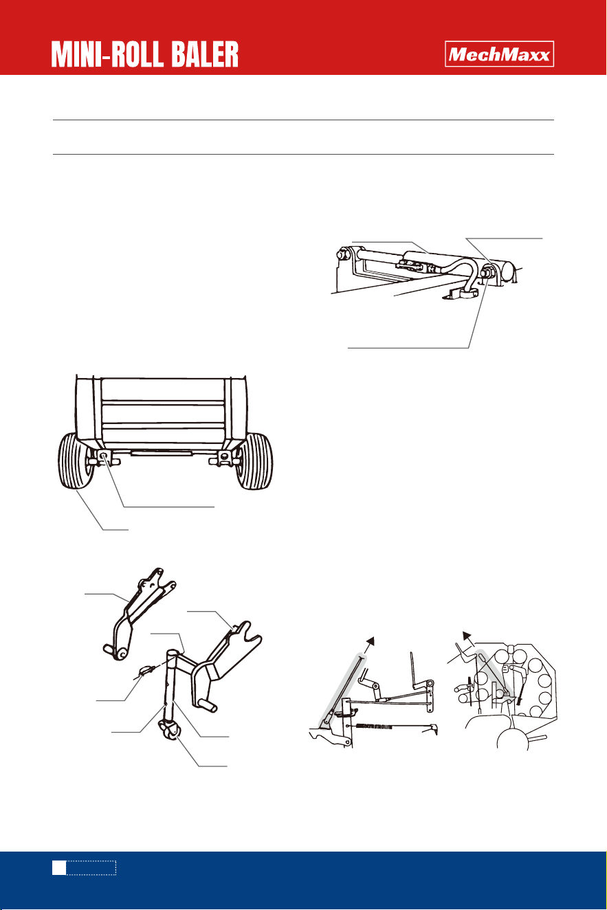
Lower link pin and upper link
Lower and upper link pins are connected with the
tractor lower links and top link.
Lever and lock plate
pick-up assay is lifted and is hold by lock plate for
transportation of the machine. Pick-up is lowered by
releasing lock plate.
Chain and bolt(lower limit)
The chain and bolt are used to adjust the height of the
pickup from the ground.
Crop cover, Cover shield and side cover
Crop cover helps to convey hay or straw smoothly to
the chamber.
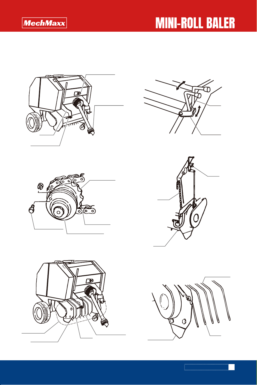
ATTACHING TO A TRACTOR
Arm
Lower link pin
Upper link
Universal joint
Bolt
Tine
Chain
Shear bolt holder
Roller chain
Sprocket
Shear bolt
Pick-up
Side cover
Rotor flush
Tine
Lock plate
Lever
Operation
Transportation
Tine
Crop cover
Side cover
4
www.mechmaxx.com
Roller chain and sprocker
Roller chain transfer the power to driver pick-up.
Friction clutch slips when over load affects to pick-up
for preventing from damaged of pick-up
Rod and bracket
Bale density can be adjusted by changing the rod
position into hole.
Rod (Indicator rod)
Rod shows to the operator the progress of making bale.
Binding device
Binding device winds twine on a finished bale.
Chamber and roll
Chamber is formed by rolls. rolls rotate themselves
and rotate baling material for making cylindrical
material inside of chamber.
Spring (tension spring)
Spring gives proper tension to roller chain.
ATTACHING TO A TRACTOR
Tension Spring
Tension arm;B
Sprocket
Gate
Tension plate
Roller chain
Frame
Tension Spring
Tension arm;A
Latch
Stopper
Control lever
Rod
(Indicator rod)
Link
Bracket
Spring
Knife
Twine casing
Arm
Binding device
Twine
Guide roll
Twine Tensioner
Binding arm
Roller chain
Sprocket
Sprocket
Friction
clutch
Bolt
Box frame
Roller
Chamber
(Inner space)
PIC shaft
Gear box
Rod
(Indicator rod)

5
www.mechmaxx.com
Hydraulic power package and lever
Hydraulic power package actuate hydraulic cylinder to
open and to close gate for bale ejaculation.
Bale ejector
The bale ejector rolls the finished bale far enough from
the machine to allow gate close.
This machine is designed to perform by attaching to
suitable size of the tractor.
If this machine is attached to unsuitable size of tractor,
it will have a possibility of giving bad affection to
durability or to operation.
Never attach the machine smaller tractor than
15HP(HB3120). for the small tractors under 25 hp
tractor shall have front ballast, otherwise it may cause
dump because the baler weight is more than 881.8 lb.
It will be a cause of serious accident lack of weight
balance.
If the machine is attached to bigger tractor than 50HP,
it will have a possibility to give damage to the machine.
Application tractor HP
HB3120 From 15 HP to 50 HP
APPLICABLE TRACTOR SIZE
ATTACHING TO A TRACTOR
Lever
Cylinder
Gate
Power package
ON
OFF
Bale ejector
Tire
6
www.mechmaxx.com
1. Package opening
Open the package and unite the parts from iron crate.
2.Details of attached parts
Make sure if all parts delivered in accordance with
packing list.
3. Process of assembling
Refer to the mark numbers on nuts and bolts necessary
for assembling in the packing list.
(1) Attach the tires on the machine and fix them by
nylon nuts and bolts.
Adjust the tire tread not to trace to the tractor wheel
tracks.
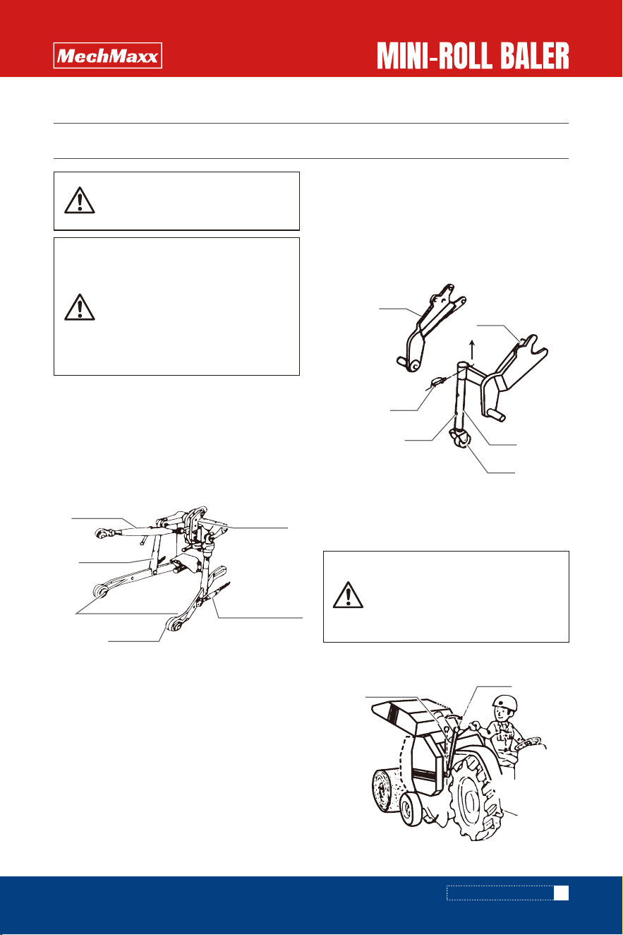
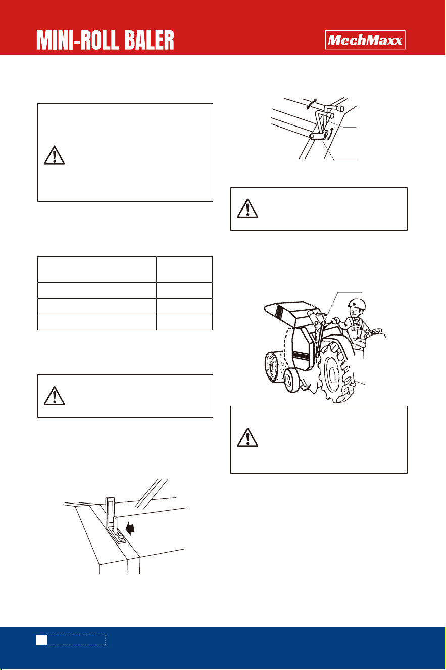
There are 2 ways to get off the tires from the baler.
1. Attach the baler to the tractor, connect the wires,
then press the switch button to open the tailgate of the
baler, the tires will roll out off the baler.
*If the tires weren't roll out, switch the stop valve, and
make sure the tailgate won't fall down, then take off
the tires.
2. This way need 3 persons, 2 person standby the left
and right side of the baler, pull up the rod( as in the
photo), another person stand at the tailgate side and
lift the tailgate, the tires will roll off the baler.
If the tires weren't roll out, switch the stop valve, and
make sure the tailgate won't fall down, then take off
the tires.
4.Take off the tire
(2) Attach stand to arm;L
(3) Extend the rod of hydraulic cylinder and align the
hole of barrel and the hole of pivot pipe.
Then apply bolt.
(4) Refer to parts list to apply other parts to the
machine
ASSEMBLE
ASSEMBLE
Nylon nut: N12
Bolt: M12x70
Tire
Caster
Stand
Operation
Delta pin
Arm;R
Arm;L
Storage
Cylinder
Pivot pipe
Bolt; M16X80
Nylon nut; M16
7
www.mechmaxx.com
1. Preparation for attachment
This machine should be attached to the standard 3P
tractor.
If the machine can not be lifted up high enough, the pin
of lift rod should be inserted into front side of hole of
lower link.
2. Attaching to a standard 3P in acordance with
following procedure.
(1) Start engine of the tradtor and drive a tractor to
backward until tips of lower link will be aligned.
Stop engine and apply parking brake.
(2) Insert left side of lower link pin into the hole of right
lower link pint.
Insert right side of lower link by same procedure above
(3) Turn adjusting screw to get the same height of left
and right lower links from the ground.
(4) If the width of lower link is small, adjust the link of
left side (look from backward) internal
(5) Lift the 3P machine by 3P connection to let the 3P
frame upright rise choose the position of main link pin
then connect and fix.
(6) Start engine of the tractor and operate the oil
pressure handle to the machine then stop the engine.
3. Attachment of power package operation rope
(7) Align the center of PIC shart and PTO shaft by check
chains and then tighten check chains to protect the
machine swing,
The breaking end of rope is fixed inside of driver’s
cab(no effect to operation)
ATTACHING TO A TRACTOR
ATTACHING TO A TRACTOR
Bystanders must keep safely distance
when the machine is attached to the
tractor or detached from the tractor.
Attach the machine to the tractor or
detach the machine from the tractor on
flat and solid ground.
If the machine is attached to a light
weight tractor, it has a possibility of
getting unstable steering.
Attach the front weight on the tractor .
Caution in operation
Connect operation rope to the tractor
not to touch with universal joint and to
have enough slackness not to stretch
in turning.
Rope
ON
OFF
Top link
Lift rod
Top link
bracket
Check chain
Left lower link
Right lower link
Caster
Stand
Operation
Delta pin
Arm;R
Arm;L
Sliding
up
8
www.mechmaxx.com
(1) Attach the buzzer at suitable position for the
operation.
(2) Connect with accessorial electric cable to power of
tractor(12V).
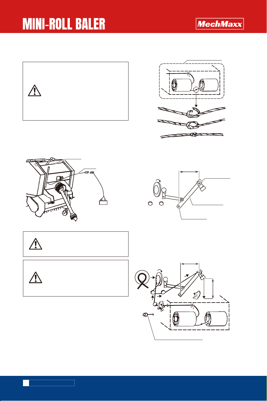
(1) Contain two twine spools in the twine casing.
(2) Connect the both ends of F and G together,and
make sure the knot as small as possible.
4. Attachment of buzzer
5. Method of twine threading
ATTACHING TO A TRACTOR
Stop the tractor engine when twine is
treaded.
Caution in operation
Use only original twine.
TG0800 (Jute 8500 feet)
TP0800 (Polypropylene 1100 feet)
Caution in operation
Adjust the length of electric cable to
get enough slackness and not to
stretch in turning.
Tie the surplus of electric cable with a
string to the tractor.
Turn off the switch when the machine
is not used.
(3) Turn twine pulley to the direction of arrow until
binding arm move from outside to inside and then stop
turning at horizontal distance 6 inch between tip of
binding arm and pivot.
(4) Thread twine tip order from 1 to 9.
Use attached twine threaser places where it is difficult
threas twine. Cut the end of twine by the length from
13.8 inch to 15 inch and hang it from binding arm tip.
Switch
Power of trackor
Cable
Twine casing
F G
Guide roll
6 inch
Binding arm
Arm pivot
Twine Tensioner
6 inch
13.8 ~15 inch
F
1
2
3
4
5
6
7
8
9
G
9
www.mechmaxx.com
ATTACHING TO A TRACTOR
ATTCHMENT OF UNIVERSAL JOINT
Danger
Never use universal joint with damaged
safety cover or without safety cover.
Inspect it if damage is found out on
universal joint.
Stop the tractor engine and disengage
PTO clutch when universal joint is
attached.
Fix chains of safety cover to the tractor
and stationery part of the machine not
to rotate safety cover.
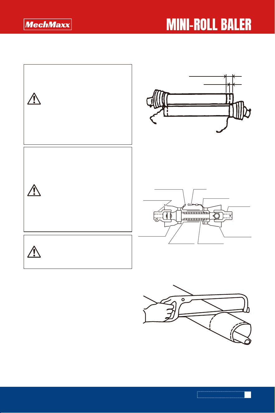
Caution
If overlap length between inner and
outer tube of universal joint is less
than 4 inch in extended position, it will
be a cause of universal joint breakage.
If the space between inner and outer
tube is less than 1 inch in retracted
positon, it will be a cause of damage.
By pushing to each other when the
machine is lifted.
Please use it with the proper overlap
of the universal joint.
Caution in operation
If universal joint makes noise when
the machine is lifted up by 3P,control
the lower linkage of 3P.
1. Universal joint length check
(1) Pull out other tube of universal joint from inner tube
of universal joint.
(2) Lift up the machine and stop the lifting at the closet
distance PTO shaft and PIC shaft.
(3) Push cramp pin of yoke and insert the yoke into PTO
shaft and push on until cramp pin comes out by spring
force.
Insert the other yoke into PIC shaft same procedure as
mentioned above.
(4) Put one universal joint on to one another universal
joint.
Mark lapping end position of outer safety cover and
inner safety cover and mark at further 1 inch inside from
lapping position.
Cut off safety cover at further 1 inch position.
(5) Lift the machine and stop lifting at the most
separted position between PTO shaft and PIC shaft.
(6) Put one safety cover on to one another cover.
If lapping lengthis less than 4 inch, replace it to longer
universal joint.
2. Method of cutting
(1) Cut off excess length of inner and outer safety
cover.
Pipe (lnner)
Safety cover
(Inner)
Safety cover
(Outer)
Clamp pin
Chain
Pipe (Outer)
Universal
joint (Inner)
Universal
joint(Outer)
Yoke with pin
Over lap length+1 inch
Over lap length
10
www.mechmaxx.com
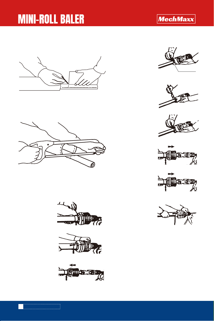
3. Method of outer safety cover removal
(1) Disassemble procedure of cover
(1) Connection to the machine
Push cramp pin of yoke and insert yoke into PIC shaft and
push on until cramp pin comes out by spring force.
(2) Connection to the tractor
Push cramp pin of yoke and insert the yoke into PTO shaft
and push on until cramp pin comes out by spring force.
4 . Connection of universal joint
(2) Assemble procedure of cover
1.Take out fix screw
2.Revolve the cover to
the position of release.
3.Pull out safety cover
from tube.
(2) Mark on inner and outer pipe the same length of cut
off safety cover from the end of inner and outer tube.
(3) Before cutting off, put rag into between safety cover
and pipe not to come into sawdust.
Cut off excess length of tube by metal saw.
(4) File cut ends and clean the surface.
Apply grease on tube and insert inner tube into outer
tube.
4.Take out the slide loop.
1.Apply oil to slide loop
channel and tube inside.
2.Open the cut mouth of
slide loop and imbed it to
the channel of tube.
3.Fit the safety cover.
4.Screw the cover tightly.
5.Fix the position with fix
screw.
ATTACHING TO A TRACTOR
Slide loop
11
www.mechmaxx.com
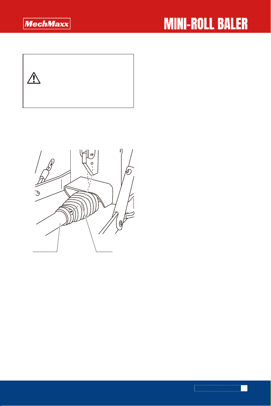
Caution
After connection of universal joint, make
sure that cramp pins of PTO side and PIC
side stay firmly in grooves of PTO shaft
and PIC shaft.
If the pins do not stay in grooves firmly,it
will be a cause of serious accident.
(3) Fix of safety cover chain
Fix safety cover chain on stationary part of tractor to
prevent from rotation of safety cover.
Slacken off chain not to stretch it in the up and down
movement of tractor 3P.
ATTACHING TO A TRACTOR
Safety cover Clain

INSPECTION BEFORE OPERATION
INSPECTION BEFORE OPERATION
INSPECTION IN TRACTOR ENGINE RUNNING
12
www.mechmaxx.com
Warning
Bystanders must be away from the
machine when gate is opened.
Lock gate by the stop valve when the
machine is checked in the gate
opening situation.
1.Inspection of the tractor parts
1.Inspection of the tractor hydraulic
Lift up the machine by controlling lever of lift up and down
for hydraulic control..
If the machine will not come down in lifting up position,
hydraulic system has no trouble. if hydraulic system has
any trouble, contact with tractor dealer for solving
problem.
2. Inspection of machine hydraulic system
(1) Inspection of machine hydraulic system fot gate
opening and closing.
2. Inspection of connecting parts
Following should be done before operation to stand long
life the machine
Inspect the tractor parts according to the tractor user
manual of the tractor.
(1)Check looseness of nuts and bolts.
Tighten loosen nuts and bolts firmly.
(2)Check if the shear bolt is sheared or not.
If it is sheared replace to new one referring sufficient.To
the parts list.
Beforehand,prepare for replacement shear bolts.
(3) Check if roller chain is properly stretched.
Adjust it in accordance with the instruction “21 pages
Adjustment of roller chain stretch”.
(4)Check the length of pick up tension if the length is
improper,adjust the length in accordance with the
instruction of “21 pages Pick-up V-belt tension”.
(5) Check whether the tension spring size is correct.
If the length is improper,adjust it in accordance with the
instruction “22 pages Adjustment of twine tensioner”.
(6)Check the sharpness of binding knife to cut twine.
If it has a problem,solve the it in accordance with the
instruction “22 pages Adjustment of binding knife”.
(7)Check if twine is enough, twine is threaded properly
and binding arm is in proper position.
If any problem is found,solve it in accordance with the
instruction “8 pages Method of twine treading”.
(8)Check damage of tine and rotor flush.
If it is damaged, replace it to new one by referring to parts
list.
(9)Check stuck hay or straw in the machine. Remove
stuck crop from the machine.
(10) Check application of oil and grease. If it is not
applied properly, lubricate in accordance with the
instruction “14 pages Lubrication spots table”.
(11)Check it tire air pressure is sufficient. If it is
insufficient, apply air until the pressure becomes
195kPa(2.0Kg/㎡)
(1)Inspection of 3P connecting parts
(2) Inspection of universal joint
3 Inspection of the machine
1)Make sure that locking pin is inserted into the hole of
low link pin.
2)Make sure that locking pin is inserted into a hole of
top link pin.
3)Make sure that check chains of the tractor are
stretched firmly.
4) If any problem is found in connection,remedy the
problem according to the instruction “Attachment to
tractor”.
1)Make sure that cramp pins stay in the groove of PTO
shaft and PIC shaft.
2)Make sure that chain of safety cover has excess
slackness.
3) Check the damage on safety cover of universal joint.
4)If any problem is found on universal joint,remedy the
problem according to the instruction “Attachment of
universal joint”.
INSPECTION BEFORE OPERATION
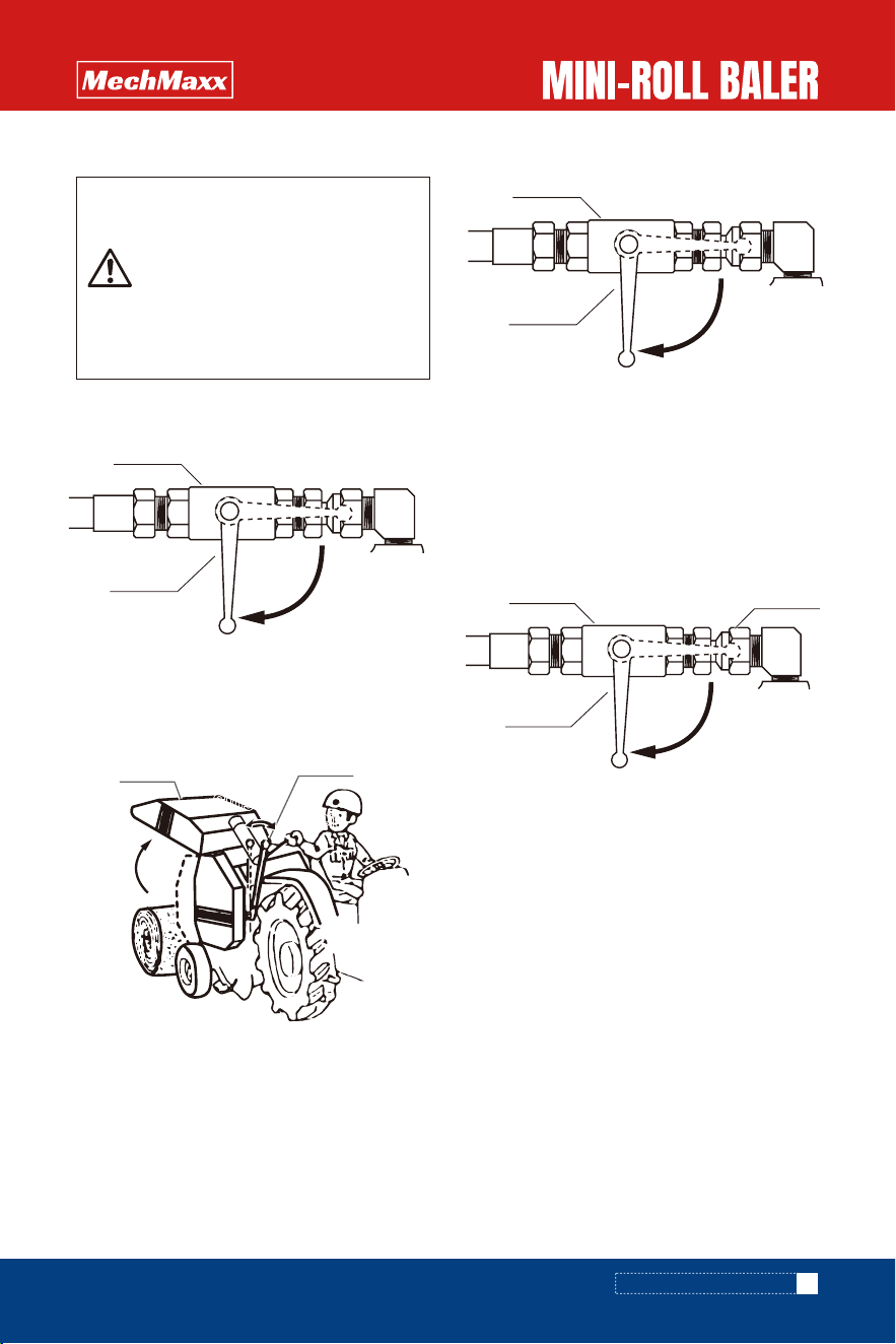
1) Turn lever of stop valve for gate opening and
closing to “Opening”position.
4) If the gate does not come down, it has no
trouble. If gate comes down, check oil leakage and
repair or replace damaged part.
5) Close the gate by turning slowly lever of the
stop valve to “Open” direction. If the air remains in
the hose or cylinder, loosen male adapter and let
the air out it. Tighten swivel adapter after
releasing air.
2) Start the tractor engine and engage PTO to rotate
PTO shaft and then open gate by operating lever of
power package.
3) Turn lever of stop valve to “close”while pulling the
lever of the power package at full opened gate
position.
13
www.mechmaxx.com
Caution
If the hydraulic hose is damaged or
hydraulic fitting is loosen,it will cause
of injuring by leaking high pressured
hydraulic oil or suddenly dropping gate
of the machine.
Replace damaged hydraulic hose or
fittings and tighten loosen fittings.
INSPECTION BEFORE OPERATION
Power package
Operation lever
Gate
Open
Close
Open
Chose
Lever
Stop valve
Open
Chose
Lever
Stop valve
Open
Chose
Lever
Stop valve
Male swivel
adapter
LUBRICATION SPOTS TABLE
Apply fresh and clean oil and grease the machine.
Apply grease to a grease nipple until old grease come
out.
1) Gear box
2) Worm gearbox
3) Power package
4)Housing
14
www.mechmaxx.com
5) Sprocket
6)Arm support
7)Crank bar
8)Universal joint
9)Tension arm pivot
10)Link pivot
11)Gate pivot
12)Roler chain
LUBRICATION SPOTS TABLE
11
3,12
1
8
2 7
5
10
5
9
12
12
9
4
Drain
Oil port
Oil port
Gear box
Drain
Grease
nipple
Grease nipple
Grease nipple
Grease nipple
Grease nipple
Grease nippleGrease nipple
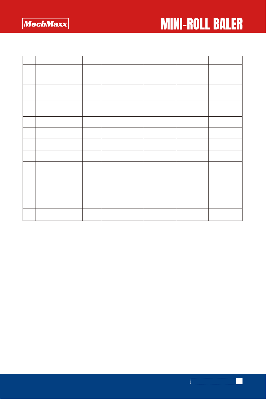
No.
1 1
1
2
2
3
4
Lubrication points
Gearbox
Worm gearbox
Power package
Housing
Gear oil; SAE 90
API GL-5
Gear oil; SAE 90
API GL-5
Gear oil; SAE 90
API GL-5
Grease ; Number 3 After operation Proper Q'ty Grease nipple
15 Sprocket Grease ; Number 3 After operation Proper Q'ty Grease nipple
16 Arm support Grease ; Number 3 After operation Proper Q'ty Grease nipple
27 Crank bar Grease ; Number 3 After operation Proper Q'ty Grease nipple
-8 Universal joint Grease ; Number 3 After operation Proper Q'ty
29 Tension arm pivot Oiling After operation Proper Q'ty
410 Link pivot Oiling After operation Proper Q'ty
211 Gate pivot Oiling After operation Proper Q'ty
412 Roller chain Grease application After operation Proper Q'ty
Grease nipple
Grease nipple
500g
1.7L
After 100 hr or
one seas
Every 100 hr
Discharge
gearbox,cleaning
before oiling
Gearbox tank
Point Kind of lubrication Changing time Q'ty Remarks
15
www.mechmaxx.com
LUBRICATION SPOTS TABLE
OPERATION METHOD
1. This machine is produced for baling grass, rice straw
and straw. Never use except this purpose.
(1) Bale for the hay which is less than 20% of moisture
content.
(2) Bale the grass for making wrapping silage which is
between 50% and 60% of moisture content.
2. Do not operate the machine after stopping rain in
muddy field. Operate the machine in well dried field.
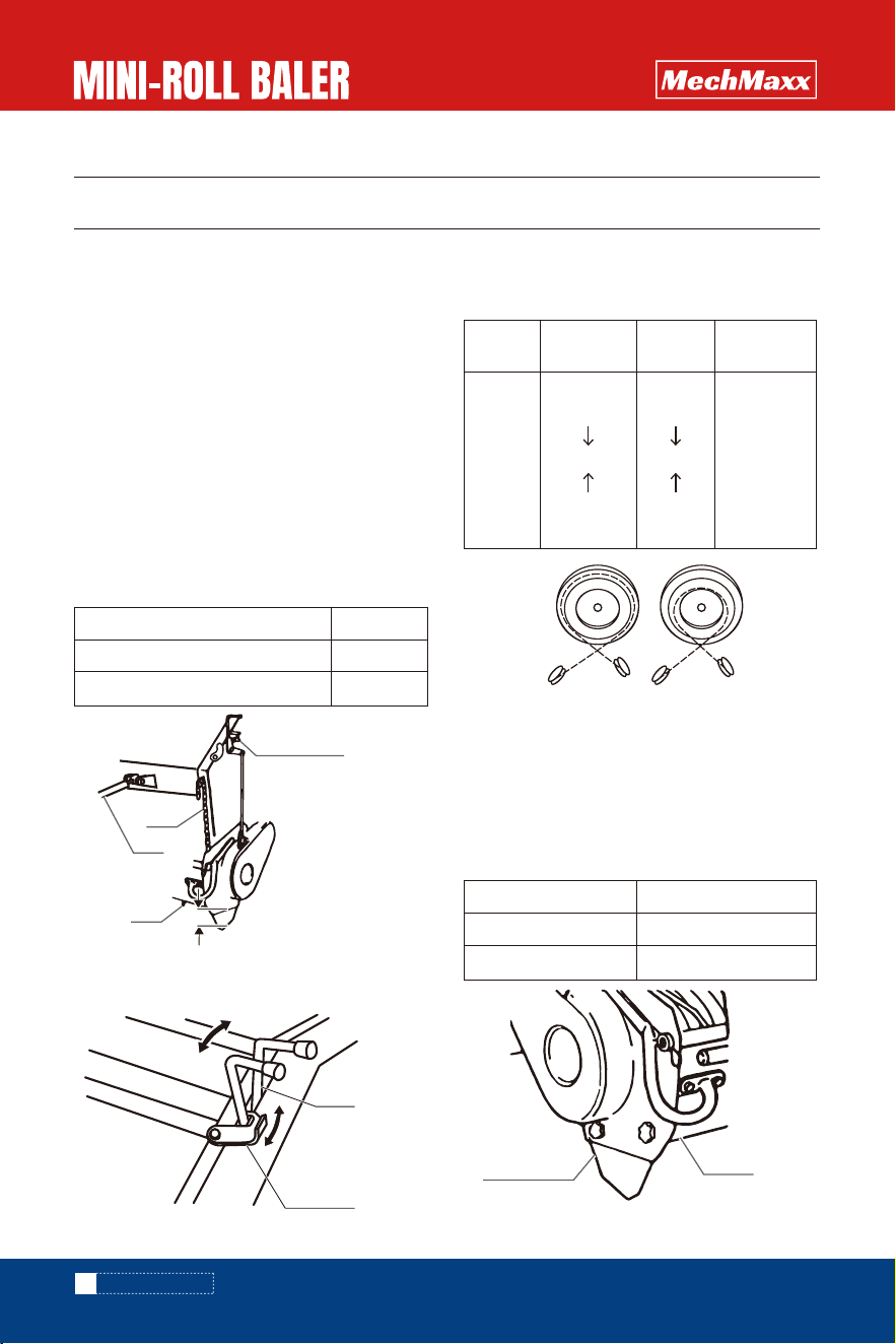
1. Adjustment of the pick-up tine height from the ground
(1) Adjust pick-up tine height from the ground by limit
chain and lower bolt.
Fine adjustment is done by top link pin of a tractor.
The winding number should be changed according to
thickness of twine.
If the twine is thicker, the winding number must be
more. Above table is the standard.
2. Adjustment of twine winding number
Adjust the twine winding number according to baling
condition and handling condition of bale.
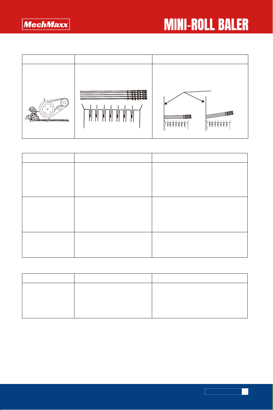
3. Adjustment of Cover shield and Side cover
(2) Select operation position and transport
position by moving the lever and lock plate.
Baling material H
Cut straw
Long straw or hay
0 inch
0.78 inch
Crop Cover shield/ side cover
Cut straw
Hay, Long straw
Attachment
Removal
Winding
number
Cut straw
Dried straw
Hay
Long straw
Crop Handling
Many
Few
Twine pulley
10
8
Big dia.
Pulley
Small dia.
pulley
16
www.mechmaxx.com
PURPOSE OF THIS MACHINE
ADJUSTMENT FOR OPERATION
OPERATION METHOD
Cover shield
Side cover
10 winding
(Cut straw)
Marry handing
8 winding
(Long straw or hay)
few handing
Lock plate
Lever
Operation
Transportation
Lower limit bolt
Tine
Chain
Top link
H
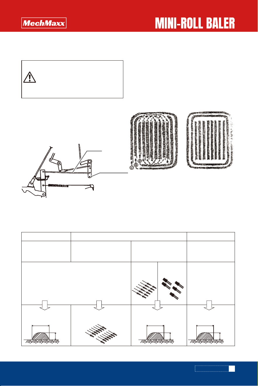
(1) Adjustment of the rod
When the rod is inserted into higher position of bracket
hole, lower density of bales are made.
When the rod is inserted into lower position of bracket
hole, higher density of bales are made.
1.Method of bale making
Make bale of the width from 27.56 inch to 31.5 inch
and the height from 11.8 inch to 15.75 inch as Uniform-
ly as possible.
The bales which are made for efficiency and smooth
operation are recommended.
Order of making windrows Finishing
(2) Adjustment by traveling speed
Lower traveling speed make higher density of bale.
Adjust the traveling speed according to condition of the operation.
Adjust the bale density smaller when the chains become hot.
4. Adjustment of the bale density
Hay Long rice straw (straw) Cut straw
Make hay/grass in a line
as Below
Straw chop off
By 3/4 rows rice combine
harvester
Operation of straws by 2
rows rice combine harvester
or in bundle
2 rows
direct drop
Operation by
bundle
Direct straw pick up is
Possible
It will be more efficient
to make straws in a line.
Pickup the straws on the
ground directly
17
www.mechmaxx.com
Caution
High density of bale requires high tractor
PTO horse power. Adjust bale density
according to the tractor size, the field
condition and the baling material.
OPERATION METHOD IN FIELD
OPERATION METHOD
Rod
Bracket
2.76-3.15 inch
1.18-
1.57 inch
2.76-3.15 inch
1.18-
1.57 inch
2.76-3.15 inch
1.18-
1.57 inch
1. Field opertion
(1) Put on the switch of the buzzer and PTO and drive the
tractor forward.
Adjust PTO speed depending on baling material condition
and the moisture content.
(4) When twine binding is finished, twine is cut and
binding stops.
Press the button to release the bale.
(5) Release the remote control button to close gate and
then start the operation.
1. Stop PTO of the tractor
2. Pull down the lever and lock it by lock plate.
3. Switch off the buzzer.
4. Lift up the machine by operating 3P lifting lever.
5. Lock 3P of the tractor not to come down the machine
in the transportation.
(2) Quantity of the baling material inside of the chamber
can know from the indicator.
The indicator rod rise up when a bale coming to complete.
And make the machine into transportation position.
(3) When a bale reaches to complete, buzzer sounds and
twine binds on a bale automatically.
Normal operation speed is 3-5 km/hr.
Adjust the operation speed depending on the field
condition.
Baling material condition,
Moisture content
PTO speed
Standard
Dried, short
Moist, stuck pick-up
540 rmp
350-450 rpm
540-600 rpm
18
www.mechmaxx.com
Warning
Bystanders must be away from the
machine when pick-up is running. Stop
the tractor engine when taking away
Stuck baling material from the pick-up.
Never touch rotating rollers. Stop the
engine of the tractor when taking away
stuck grass between rollers.
Warning
Bystanders must be away from the
machine when the gate is opened.
Do not eject a bale at inclined field. Eject
a bale always level field.
Caution in operation
Do not stop PTO while twine is binding
round on a bale
Caution in operation
If the twine binding will not start, forward
about 1m.
TRANSPORTATION
OPERATION METHOD
Rod
(Indicator rod)
Remote
control box
ON
OFF
Lock plate
Lever
Operation
Transportation

OUT OF SEASON FOR STORAGE
Maintain the machine for keeping long life.
1.Remove baling material form pick-up in the field.
2. Remove piled dust from the binding unit.
3. Remove baling material stuck material on the rolls.
4. Remove dust from driving device in the side of the
machine.
5. Replace damaged or worm parts to new ones.
6. Inspect driving and connection parts in accordance
with inspection spots table.
7. Lubricate in accordance with lubrication spots table.
8. Apply grease on PTO shaft, PIC shaft, power joint and
other parts which are not painted to prevent from the
rust.
9. When machine and tractor separate, support rod
should be set down.
10. After machine and tractor separate, universal joint
should be detached.
11. Disconnect the bale counter and battery, turn off
the bale counter after working.
1. Slid down support rod and insert pin into the highest
position of a hole.
2. Lower hydraulic control lever of a tractor until tires of
the machine contact with the ground.
3. Stop the tractor engine and apply parking brake.
4. Detach power joint from the tractor PTO shaft.
5. Detach right side of lower link, left side of lower link
and top link.
19
www.mechmaxx.com
Caution
Never try to remove blocked material
when the machine is running. Disengage
clutch of PTO drive, stop tractor engine
and make sure all moveable parts stop.
MAINTENANCE AFTER OPERATION
DETACHING FROM TRACTOR
1. Clean every parts of the machine.
2. Inspect moving parts and connecting parts in
accordance with inspection and maintaince points
table.
If any damaged or worn parts are found, they must be
replaced with new ones.
3. Apply grease or oil in accordance with lubrication
points table.
Apply oil to rotating, pivoting parts and sliding parts
such as clump pin of power joint.
Apply grease on PTO shaft, PIC shaft and spine holes of
power joint yoke.
4. Paint or apply oil on damaged surface of parts to
prevent from the rust.
5. Store the machine in well ventilating indoor.
6. If there is no choice but to keep the machine in out
door, cove the machine with a plastic sheet.
7. Take off the cell battery in the bale counter.
STORAGE IN OUT OF SEASON
OUT OF SEASON FOR STORAGE
INSPECTION AND MAINTENANCE
20
www.mechmaxx.com
Warning
Stop the tractor engine and disengage
PTO when adjustment of twine binding
device is done.
Lock stop valve for fixing gate when
inspection or adjustment is done at
opening gate.
Caution
Lock the hydraulic circuit of tractor when
the machine is Iifted up for maintenance
or for inspection prevent from machine’s
failing down.
Inspection or maintenance should be
done on solid ground or conerete.
Never inspect or maintain on slant.
uneven,or soft ground.
Stop the tractor engine and make sure alI
machine parts stop when jnspection or
Inspection and maintenance should be done regularly to
obtain good condition.
Inspect and maintain each pads In accordance with
inspection and maintenance table to prevent from
accident by poor maintenance.
Since tines,shear bolts,knives and twine are
consuming pads,replace worn parts with new ones or
replenish with new ones.
Hours
After initial 1 hour
operation
Before operation
After operation (or
before operation)
Out of season
Looseness of all nuts and bolts Slackness
of roller chains
Cleaning up
Wear of pick up tines
Wear of binding knife
Shear of shear bolt
Twine consumption
Running out of battery cell for bale counter
Tires air pressure
Looseness and loss of nuts,bolts and pins
Abnormal noise or vibration in driving
Breakage of power safety cover of roller
chain cover
Lubrication to rotating and moving parts
Adjustment of each parts
Broken parts
Worn parts
Cleaning up each parts
Damage of painting
Worn pivoting pads or pins
Repair
Replacement with new one
Painting or applying oil
Replacement to new ones
Replacement
Replacement
Replacement/Replenishment
Replenishment
Replacement
(1.5v - AA5 cell battery)
1 95kPa(2.0kg/cm2 )
Tightening and replenishment
Remedy in accordance with
trouble shooting table 24 pages
Replacement
Lubrication in accordance 14 pages
Lubrication points table
Adjustment in accordance 21 pages
adjustment of each pads
Tightening
Adjustment in accordance with "21 pages
Tension adjustment of roller chain"
Items for checking Remedy
INSPECTION AND MAINTENANCE
21
www.mechmaxx.com
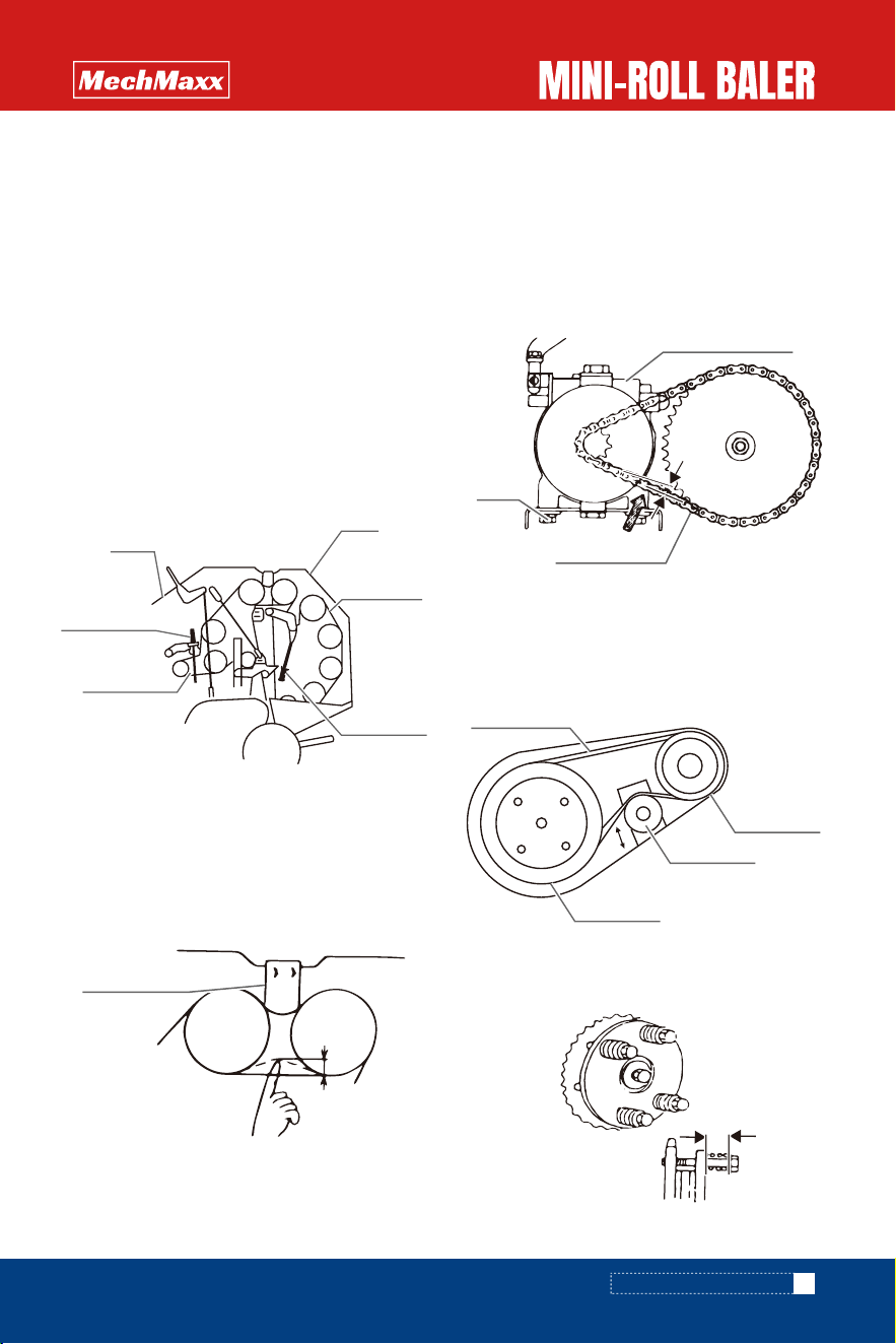
1.Roller chain tension adjustment
Roller chain is elongated by usage little by little.Adjust
tension of roller chain for transmitting the power
smoothly.
Since the roller chain is especially elongated by initial
usage,adjust tension after initial usage.
2.Adjustment of drive part for pickup assay
(1)Loose bolt, turn the tension wheel to adjust chain,
after adjustment,fasten the bolt.The most suitable
tension is 0.1 inch pressed down at the centre of the
chain.
(2)Adjustment of sliding clutch
Springs(4)are adjusted to 1 inch.
(1)Adjustment of tension spring
Adjust tension of roller chain on the frame and on gate
by adjusting the length of the tension springs.
The length of spring is mentioned below.
(2)Adjustment of tension plate
Adjust tension of roller chain between frame and gate
by tension plate.
Proper roller chain tension gives 0.1 inch deflection
when roller chain is pushed by a finger.
(3)Adjustment of power package
Tension for roller chain to drive the power package is
adjusted by moving position of the power package.
Push middle part of chain between both sprockets by
finger.
Correct tension is approx. 0.2 inch of deflection when
the chain is pushed.
H1=1.42 inch
H2=1.5 inch
ADJUSTMENT FOR EACH PARTS
INSPECTION AND MAINTENANCE
Tension Spring
Roller chain
Gate
Frame
Tension Spring
Tension arm;A
Roller chain
Sprocket
Sprocket
Bolt
1 inch
Power package
Roller chain
Bolt
0.2 inch
Tension plate
0.1 inch
Caution
Apply original replacement knife of the
machine
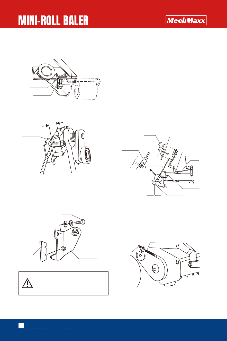
3. Adjustment of twine tension
Adjust spring length to 1.38 inch.
6. Adjustment of the bale density detection link
(1) Adjust the clearance between stopper and collar on
gate by bolt. L1=0.04-0.08 inch is proper.
(2) Remove the pin from the rod, pull down the rod,
adjust the position of the fork hole and the hook hole by
fork end.
Adjust the dimension between lower side of fork end
slot and the hole of stopper as mentioned bellow in
above situation. L2=0.08 inch is proper.
(3) Adjust the dimension between latch and cutout of
control bar as below. L3=0.3 inch is proper.
Adjust this dimension to L3=0.23 inch.
If bale weight is too heavy(More than 55.2 lb) because
of too much moisture content.
4. Adjustment of arm tension spring
Adjust length of the spring at 0.31 inch
5. Adjustment of binding knife
Remove the knife and use the opposite side if the knife
is dull.
Replace the knife to new one if reversed knife is dull.
7. Adjustment of PIck-up suspension
Proper suspension springs length on both sides Of
pickup assay is L=1.9 inch.
Adjust spring length according to field condition if the
pick-up does not follow well the field unevenness.
Both springs length should be the same after the
adjustment.
L3= 0.17 inch
22
www.mechmaxx.com
INSPECTION AND MAINTENANCE
1
2
0.31 inch
Latch
Stopper
Control lever
Fork end
Fork end
Rod
Release
Collar
L1
L2
L3
Bolt
Knife
Knife arm
Bolt
Spring
Spring
Tension plate

23
www.mechmaxx.com
8. Adjustment for gate closing speed
Adjust the rotating button on the control valve to adjust
the gate closing speed.
Speed is decreased by turning it to right or is increased by
turning it to left.
INSPECTION AND MAINTENANCE
Slow
Fast
Warning
* stop the tractor engine and disengage
PTO when adjustment is done.
* lock gate by closing stop valve not to
fall down when doing inspections or
adjustments
Caution
* lock the hydraulic circuit of tractor
when the machine is lifted up for
maintenance or inspection to prevent
from machine's falling down
* Inspection or maintenance should be
done on solid ground or concrete. Never
inspect or maintain on slant, uneven, or
soft ground.
* Stop the tractor engine, disengage PTO
and make sure all moving parts stop
when doing inspections or adjustments.
Ask to the dealer by informing followings
if the cause of trouble and trouble
shooting is not clear.
* PICK UP ASSAY
TROUBLE SHOOTING TABLE
TROUBLE SHOOTING
Fault
* Abnormal noise is made
* Material is not picked
up cleanly
*Baling material is
clogged between pick-up
and chamber.
*Pick-up assay does
not rotate
* Breakage of tine
* Breakage of rotor flush
* Winding of hay or twine
* Breakage of leading track roller
bearing
* Wrong pick-up setting
* Too fast traveling speed
* Breakage of tine
* Too fast PTO rotation
* Obstruction by side cover and cover
shield
* Too fast traveling speed
* Too much declined pick-up
* Shear bolt broken
* The chain loose or fall down
* Obstacle of the side plate and plate
cover
* Tine replacement
* Rotor flush replacement
* Remove of winding material
* Replacement of cam roller bearing
* Adjust the distance of the pickup assay and
the ground
* Reduction of traveling speed
* Replace the tine
*Shortening top link for obtaining forward
declined machine position
* Adjust the PTO speed
* Take off the side cover and cover shield
* Reduce tractor speed
* Move up the pickup assay by lift and reset
the position of chain
* Replace the shear bolt
* Adjust the chain or replace it
* Take off the side plate and plate cover
Possible cause Remedy
Adjust the machine in accordance with trouble shooting
table if it does not work well.
24
www.mechmaxx.com
TROUBLE SHOOTING
* ROLLER
* BUZZER
Fault
* pick-up pushes long
stem rice straw to
forward
*Match the width of the straws to
the width of pickup assay.
* Picking-up straws from right side of pick-up
assay.
Possible cause Remedy
25
www.mechmaxx.com
Fault
* Roller makes
abnormal noise
* Material is winding On
roller
*Heat generate in
Roller chain
* There are straws or mud on roller or
straws clogging
* Insufficient lubrication
* Insufficient roller chain tension
* Dent in roller
* Too fast PTO rotation
* Material clogged in pick up assay
* Dent in roller
*Too high bale density
*Insufficient lubrication to roller chain
*Insufficient roller chain tension
* Remove the wrapping straws, mud or clogged
materials
* Lubricate the roller chain
* Adjustment it
* Replacement dent roller with new one
* Adjustment of PTO rotation speed
* Remedy in accordance with"pick-up" trouble
shooting
* Replacement dent roller with new one
*Adjustment the bale density
*Application grease to roller chain
*Adjust roller chain tension
Possible cause Remedy
Fault
* Buzzer does not sound * Switch off
* Didn’t connect wire
* Wrong cable connection
* Too much distance between switch
lever and binding arm
* Switch on
* Check and connect with the tractor
* Correction of cable connection
* Replacing broken cable with new one
* Adjustment of switch location
Possible cause Remedy
TROUBLE SHOOTING
Turn up root of straw
26
www.mechmaxx.com
* BINDING
* GATE
Fault
*Binding does not work
when bale is finished
* Binding device work
before reaching to
setting density
* Twine comes off from
bale
* Twine is not cut
smoothly
* Binding rope is not set in correct
initial position
* Insufficient lubrication
* Rope tension spring is wrong
* Rope fall down from pulley
* Twine is tangled or caught
* Lower density in bale left side
* Binding arm does not rise up
* Twine tip does not come in rolling
chamber
* Binding is not set in correct initial
position
* Leading rope is too long because of
dull knife
* Binding too less rope
* Rope tension is too loose
* Adjustment in according with 8 pages.
* Lubricate it
* Adjustment tension spring
* Check and reset the ropes
* remove tangle and catch of twine
* Supply of larger quantity of straws to left side
of the pickup assay
* Lubrication and adjustment of falling speed by
double nuts.
* Adjust falling down speed of twine arm not to
be ahead of twine falling
* Remove obstacles and let rope tip into rolling
chamber.
* Reset the binding arm.
* Replacement of knife and adjustment of
leading twine length in accordance with 8 pages.
* Adjust binding laps
* Tighten nylon nuts for 1 circle or 2 circles
Possible cause Remedy
Fault
* Bale does not come out
* Gate does not open
* Density too high density
* field ridges off wide
* Declined field
*Stop valve was closed
* Leakage or breakage of hydraulic
ropes
* Locking hook position incorrect
* Disengagement of PTO
* Insufficient of power package oil
* Adjust bale density
* Adjust it
* Ejection of a bale in even place
* Opening stop valve
* Repair it and let air out before using
* Adjust it
* Rotate the PTO shaft and eject bale while
PTO is running.
* Add hydraulic oil in the power package.
Possible cause Remedy
TROUBLE SHOOTING

If you do not see the cause of a trouble or how to repair it, notify the following items to the supplier of the machine.
1. The name of machine.
2. Model.
3. Serial number.
4. Details of trouble(explain fully).
27
www.mechmaxx.com
* SHEAR BOLT
Fault
* Shear bolt is cut
* Too high PTO speed
* Clogging straws in rollers
* Obstacles in pick-up assay
*The width line of the straws too wide
* Looseness of shear bolt
* Operation in normal PTO speed
* Stop the machine, take out clogged straws.
* Stop the machine, take out clogged straws.
* Adjust it
* Tight the shear bolt
Possible cause Remedy
* UNIVERSAL JOINT
Fault
* Abnormal noise * Insufficient Lubrication
* Too much sharp angle of universal
joint
* Application grease to sliding pipes, spiders
and mounting part of safety cover
* Adjustment of tractor top link length, lower
link stabilizer and lower link upper limit.
Possible cause Remedy
* BALE DENSITY DETECTION LINK
Fault
* Bale density is loose * Exceeding bale density operation
because of not sounding buzzer
* Wrong dimension of bale density
positions
* Remedy in accordance with "Buzzer" in trouble
shooing
* Adjust the bale density by proper positions.
Possible cause Remedy
TROUBLE SHOOTING

1. When ordering a part, specify the following items.
A. Machine name.
B. Model name.
C. Part name (see parts list).
D. Part no (see parts list).
E. Quantity (see parts list).
PARTS LIST
28
www.mechmaxx.com
HOW TO ORDER PARTS
The spare parts for this machine will be supplied for
nine years after manufacturer of this machine is
stopped. It may take some time to deliver a special
part, however, even in this period.
The spare parts will not be supplied after the above
period as a rule, If you make a request for supply of a
spare part after the above period,however.we can
show you the delivery time and cost of that time.
SUPPLY TIME(PERIOD) OF SPARE PARTS
PARTS LIST
29
www.mechmaxx.com
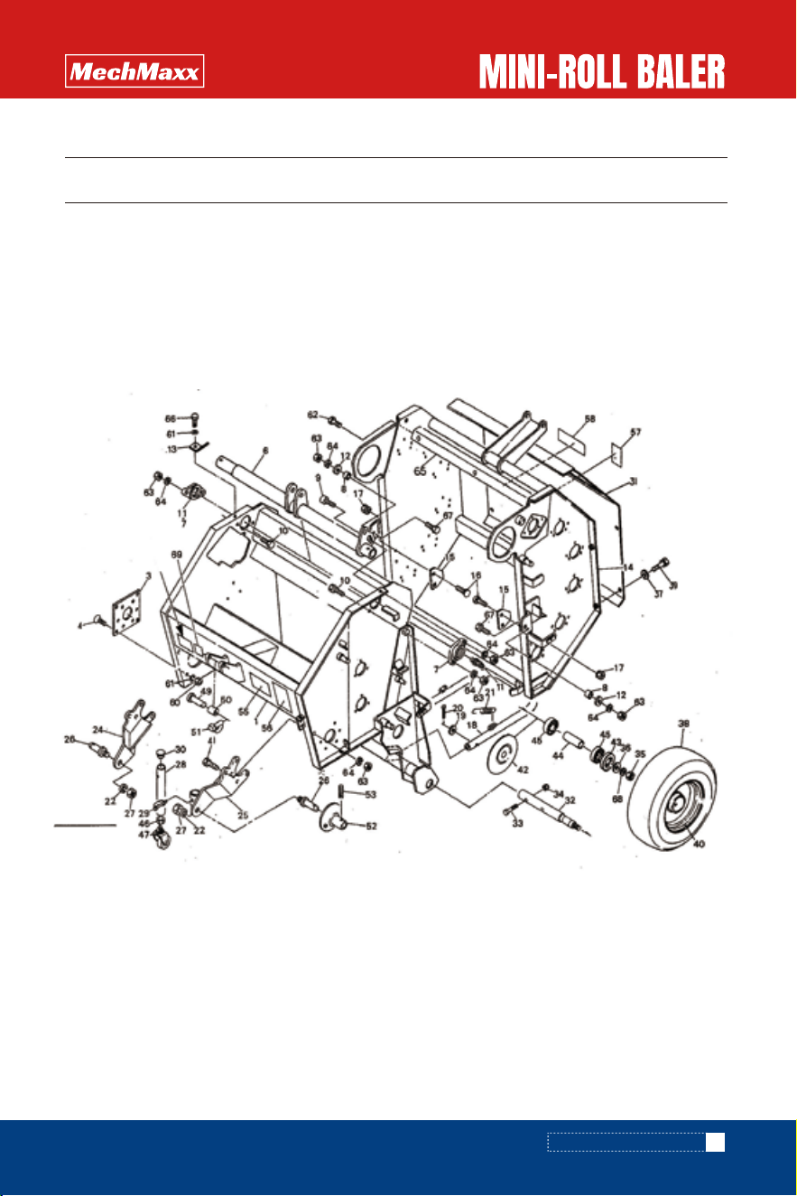
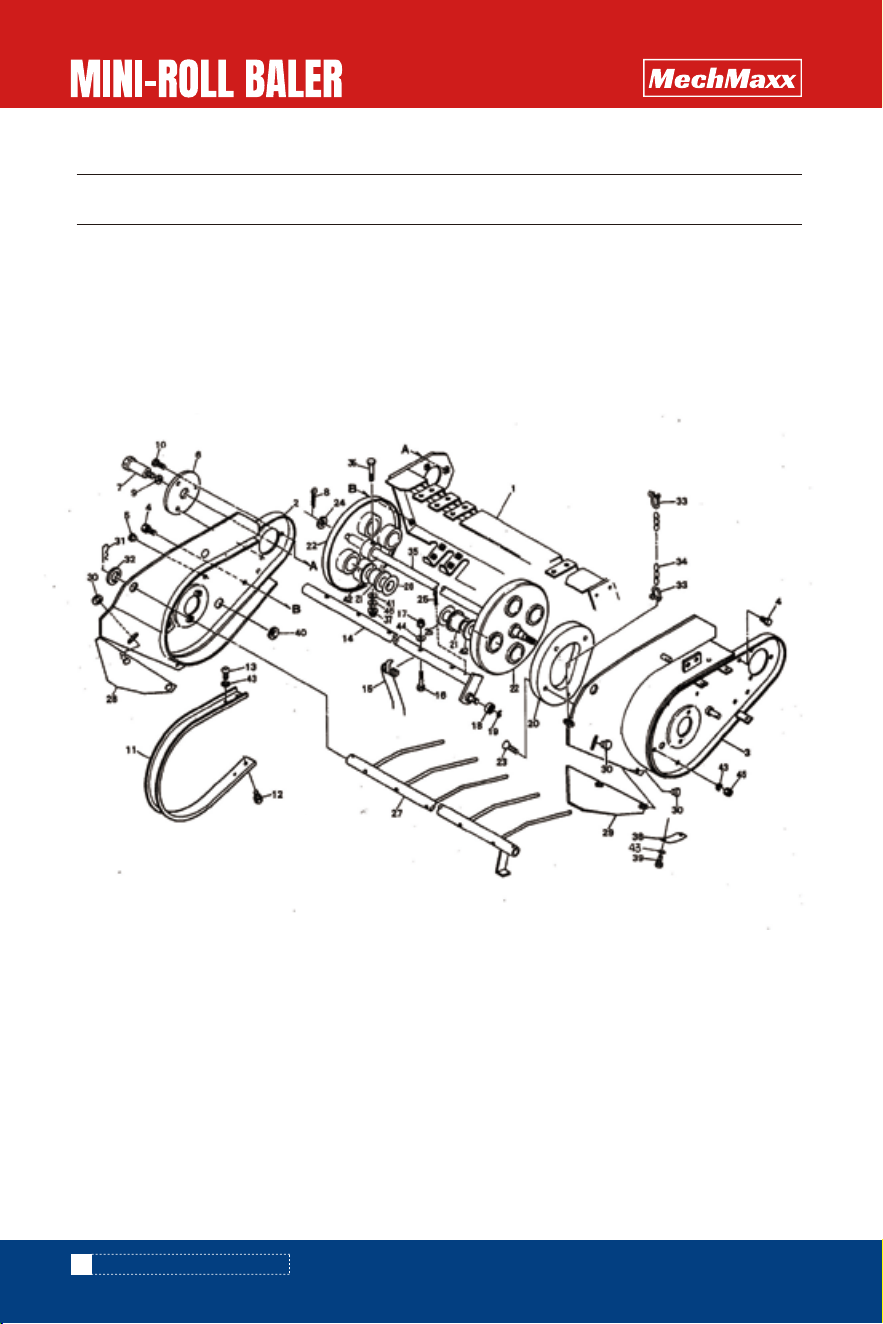
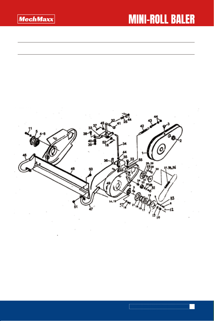
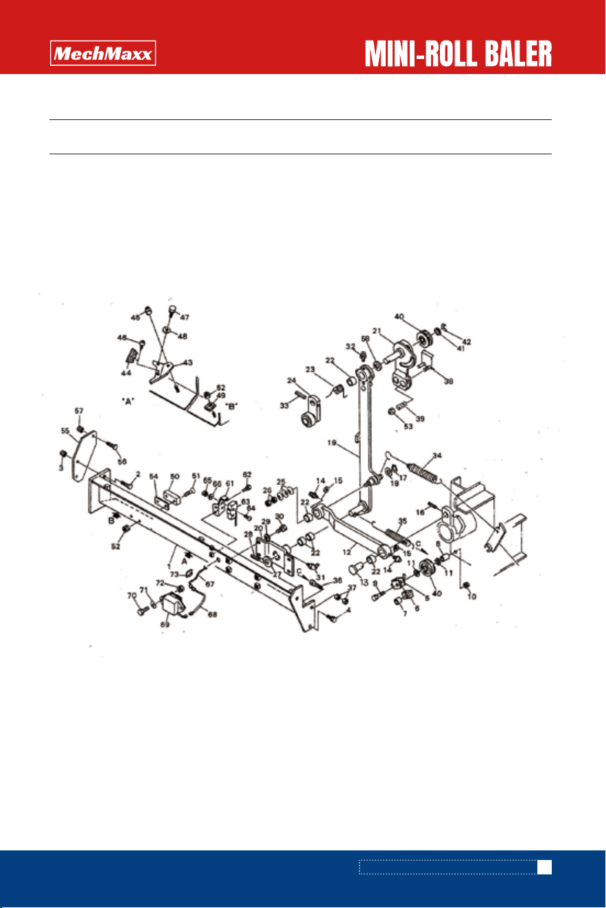
PARTS DIAGRAM(Frame assy)
PARTS DIAGRAM(FRAME ASSY)

30
www.mechmaxx.com
PARTS LIST(Frame assy)
PARTS LIST(FRAME ASSY)
1
l
4
1
2
2
1
3
2
2
l
l
2
4
4
l
l
1
2
2
1
l
2
2
1
1
l
1
2
No. DRAWING NO. QTY
1
3
4
6
7
8
9
10
11
12
13
14
15
16
17
18
19
20
21
22
24
25
26
27
28
29
30
31
32
HB3210.1-01-00
HB3210.1-02
GB5786-86
HB3210.1-03-00
HB3210.1-04
HB3210.1-05
GB70.1-2000T
GB5786-86
GB1152-79
GB97.1-85
HB3210.1-06
HB3210.1-07-00
HB3210.1-08
GB6710-86
HB3210.1-09
GB97.1-85
GB91-87
HB3210.1-10
GB93-87
HB3210.1-11-00
HB3210.1-12-00
HB3210.1-13
GB6710-86
HB3210.1-14-00
HB4187-1989
HB3210.1-21
HB3210.1-15
HB3210.1-16
DESCRIPTION
HB3120 front frame CP
Connecting plate
Bolt Ml0×25 (8.8)
pivot pipe CP HB3120
top cover
sleeve
HEXAGON SOCKET HEAD SCREW
Bolt M12×30 (8.8)
grease nipple ONB6 M6×1
washer 12.5×3.2
Hanging plate
rear frame CP HB3120
Steel plate
square neck bolt M8×15 (8.8)
Nut M8 (8.8)
ejector rod CP
Washer 10
Split pin 3.2×16
extension spring A
spring washer 22
Connectting arm CP: R
Connecting arm CP: L
Connection pin
Hexagon nut M22XI.5(8.8)
Supporting rod CP; 450A
bayonet pin 9
cover
HB3120 Rear cover
wheel axis

2
2
2
4
9
2
9
2
2
2
2
2
4
2
1
l
1
l
l
1
1
4
5
2
8
8
l
1
2
2
1
No. Drawing No. QTY
33
34
35
36
37
38
39
40
41
42
43
44
45
46
47
49
51
55
56
57
58
60
61
62
63
64
65
66
67
68
69
GB5786-86
GB6710-86
GB6710-86
GB860-87
GB97.1-85
GB1192-82(400-12)
GB5786-86
HB3210.1-17
GB5786-86
GB297-84
GB6710-86
HB3210.1-18
DIN11024-1973
HB3210.1-21
HB3210.1-22
HB3210.11-19
HB3210.1-23
GB6710-86
GB93-87
GB5786-86
GB6710-86
GB93-87
HB3210.1-19-00
GB5786-86
GB5786-86
GB93-87
HB3210.1-24
DESCRIPTION
Bolt M12×70 (8.8)
Nylon locking nut M12
HEXagon NUT M14
Washer 14
Flat washer 8
Tire 5.70/5.00-8
Bolt M8×16 (8.8)
hub
Bolt M12×55 (8.8)
cover
cover
bush
Bearing 6205-2RS
HEX NUT M20 (8.8)
caster;100
Topper Connecting pin
battle pin;9
warning sticker
warning sticker
warning sticker
Sticker: factory name
hexagon nut Ml0 (8.8)
spring washer 10
Bolt M8×25 (8.8)
hexagon nut M12
srping washer 12
Bracket CP
Hexagon bolt Ml0×25 (8,8)
Hexagon bolt M12×50 (8.8)
Spring Washer 14
sticker: RPM
31
www.mechmaxx.com
PARTS LIST(FRAME ASSY)
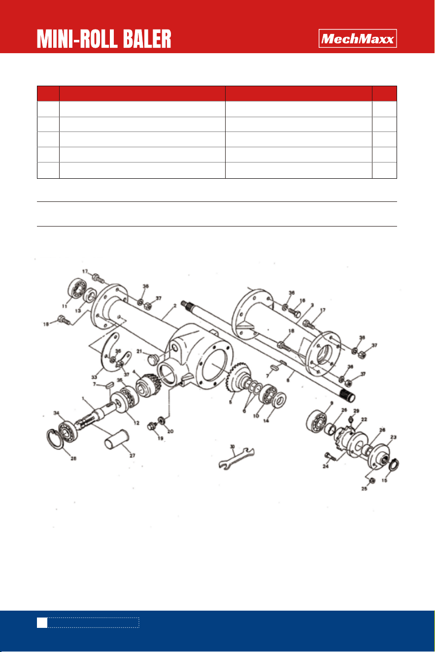
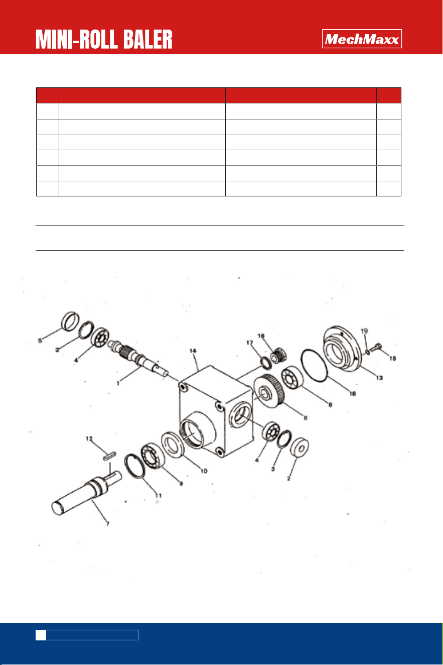
PARTS DIAGRAM(Gearbox assy)
32
www.mechmaxx.com
6
10
12
12
2
No. Drawing No. QTY
HB3210.1-20-00
GB/T12-1988
GB6710-86
GB93-87
GB1192-82(400-12)
DESCRIPTION
cover shell bracket: CP
square neck bolt :M8×20 (8.8)
nut:M8 (8.8)
spring washer: 8
Inner tire;16×6.50-8
PARTS DIAGRAM(GEARBOX ASSY)

PARTS LIST(Gearbox assy)
1
1
1
1
1
2
2
1
1
1
1
1
1
1
1
6
4
8
1
1
1
1
1
11
11
2
1
1
1
No. Drawing No. QTY
1
2
3
4
5
6
7
8
9
10
11
12
13
14
15
16
17
18
19
20
21
22
23
24
25
26
27
28
29
HB3210.2-01
HB3210.2-02
HB3210.2-03
HB3210.2-04
HB3210.2-05
HB3210.2-10
GB1096-79
HB3210.2-06
GB297-84
GB297-84
GB297-84
JB2600-80
JB2600-80
JB2600-80
GB894.1-86
GB5786-86
GB5786-86
GB5786-86
HB3210.2-10
HB3210.2-07
HB3210.2-08
GB5786-2000
GB6710-86
HB3210.2-11
GB893.1-86
GB1152×79
DESCRIPTION
input shaft
gear box
gear case
bevel gear 12T
bevel gear 22T
shim
Flat key 7×7×25
shaft
Bearing 6305-2RS
Bearing 6305
Bearing 6304-2RS
oil seal D40×62×10
oil seal D25×45×7
oil seal D25×52×8
shaft retaining ring 25
Bolt M10X25 (8.8)
Bolt Ml0×35 (8.8)
Bolt Ml0×50 (8.8)
Screw plug:Ml0
Screw Plug washer:10
plug
Sprocket CP;16T
flange
shear bolt ;M6×30
Nut M6
bush
Shaft sleeve PIC; 35
Retaining washer 62
Grease nipple ONA M6Xl
33
www.mechmaxx.com
PARTS LIST(GEARBOX ASSY)
1
1
1
18
12
No. Drawing No. QTY
33
34
35
36
37
HB3210.2-09
GB297-84
GB297-84
GB93-87
GB6710-86
DESCRIPTION
Steel plate;4.5
Bearing 6007-2RS
Bearing 6206
Spring washer 10
nut Ml0 (8.8)
34
www.mechmaxx.com
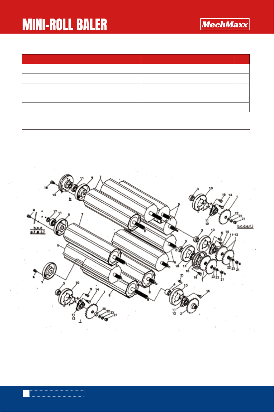
PARTS DIAGRAM(Roller assy)
PARTS DIAGRAM(ROLLER ASSY)

35
www.mechmaxx.com
PARTS LIST(Roller assy)
PARTS LIST(ROLLER ASSY)
11
1
9
1
5
1
3
1
10
10
20
18
1
48
3
9
10
1
18
2
9
9
9
1
No. Drawing No. QTY
1
2
3
4
5
6
7
8
9
10
11
12
13
14
15
16
17
18
19
20
21
22
23
25
HB3210.3-01
HB3210.3-02
HB3210.3-03
HB3210.3-04
HB3210.3-05-00
HB3210.3-06-00
HB3210.3-07-00
HB3210.3-08-00
HB3210.3-09-00
HB3210.3-10-00
GB7810-87
GB/T 7813-1998
HB3210.3-11
GB5786-86
GB5786-86
GB5786-86
GB894.1-86
HB3210.3-12
GB6710-86
GB860-87
GB93-87
HB3210.3-13
DESCRIPTION
sprocket;22T
sprocket;22T
bush;A
bush;B
Roller CP;1
Roller CP;2
Roller CP;3
Roller CP:4
flange CP
flange CP
Spherical ball bearings CS205-2RS
bearing seat
cover plate
Bolt M8×20 (8.8)
boltM8×25 (8.8)
boltM8×30 (8.8)
shaft retaining ring 25
cover plate
rivet:6×6
rivet;6×10 rivet
Nut M12
washer:Φ13×4.5
spring washer 12
bush
36
www.mechmaxx.com
PARTS DIAGRAM(Chain transmission assy)
PARTS DIAGRAM(CHAIN TRANSMISSION ASSY

37
www.mechmaxx.com
PARTS LIST(Chain transmission assy)
PARTS LIST(CHAIN TRANSMISSION ASSY)
1
1
1
2
2
1
1
6
5
2
2
2
2
2
2
2
2
1
1
1
3
No. Drawing No. QTY
1
2
3
4
5
6
7
9
12
13
14
15
16
17
18
19
20
21
22
23
24
HB3210.4-01-00
HB3210.4-02-00
HB3210.4-03
GB5786-86
GB860-87
HB3210.4-04
HB3210.4-05
HB3210.4-05
GB97.1-85
GB
GB91-87
GB860-87
GB91-87
HB3210.4-06
HB3210.4-07
GB/T1243-2006
GB/T1243-2006
GB/T1243-2006
GB/T1243-2006
DESCRIPTION
pulley bracket CP;A
pulley bracketCP;B
tension plate
Spring washer, bolt M8×25 (8.8)
Washer 8
Shaft 650
steel wire retaining ring:S
Pulley CP
shaft retaining ring 17
pull rod HB3120
flat washer 10
nylon locking nut Ml0
split pin 3.2×16
Washer 21×1.5
split pin 3.2×32
spring
spring seat
Chain 50SH-144-1 HB3120
Chain 50SH-126-1 HB3120
Chain 10A-42×l
chain joint 50SH
38
www.mechmaxx.com
PARTS DIAGRAM(Picking-up assy)
PARTS DIAGRAM(PICKING-UP ASSY)

1
1
1
5
5
1
1
1
1
3
11
22
22
4
24
24
24
4
4
1
8
2
4
2
8
12
1
1
1
No. Drawing No. QTY
1
2
3
4
5
6
7
8
9
10
11
12
13
14
15
16
17
18
19
20
21
22
23
24
25
26
27
28
29
HB3210.5-01-00
HB3210.5-02-00
HB3210.5-03-00
GB5786-86
HB3210.5-18
HB3210.5-04
HB3210.5-05
GB91-87
GB93-87
GB5786-86
HB3210.5-06
GB5786-86
RBT08020
HB3210.5-07-00
HB3210.5-08
GB5786-86
GB/T3098.9-2002
GB7810-87
GB894.1-86
HB3210.5-09
HB3210.5-10
HB3210.5-11-00
GB/T 70.3-2008
HB3210.5-12
GB91-87
GB860-87
HB3210.5-13
DESCRIPTION
picking-up Assy bracket CP
picking-up Assy bracket CP;R
picking-up Assy bracket CP;L
bolt M8×20 (8.8)
cover:9
Steel plate
axis
Split pin 5×36
Spring washer 14
Bolt M8×25 (8.8)
Protecting spring teeth
bolt M8×20 (8.8)
HEXAGON SOCKET flat HEAD SCREW
Teeth rod CP
spring
bolt M8×55 (8.8)
Nylon locking nut M8
Bearing 6201-2RS(35×12×10)
Shaft retaining ring 12
Leading track
nylon sleeve
Racket CP
HEX SOCKET Countersunk head screw
shim
split pin 5×56
Washer 35×1.2
Spring teeth assy CP
Side cover shield (Optional)CP;R
Side cover shield (optional)CP;L
39
www.mechmaxx.com
PARTS LIST(Picking-up assy)
PARTS LIST(PICKING-UP ASSY

4
2
3
2
1
1
2
2
1
2
1
2
8
28
24
4
2
No. Drawing No. QTY
30
31
32
33
34
35
36
37
38
39
40
41
42
43
44
45
46
GB860-87
HB3210.5-15
GB5786-86
GB/T3098.9-2002
HB3210.5-16
GB5786-86
HB3210.5-17
GB860-87
GB860-87
GB93-87
GB860-87
GB6710-86
GB93-87
DESCRIPTION
Plum nut(optional) M8
B Pin 19×3
washer
D Shackle;6-1/4
Rectangle welding chain 4×23P×32
axis
Bolt Ml0×70 (10.9)
Nylon locking nut Ml0
steel plate
Bolt M8×12 (8.8)
cover
Washer 10
Washer 43×3.5
Spring washer 8
Washer 8
Nut M8 (8.8)
spring washer 10
40
www.mechmaxx.com
PARTS LIST(PICKING-UP ASSY
41
www.mechmaxx.com
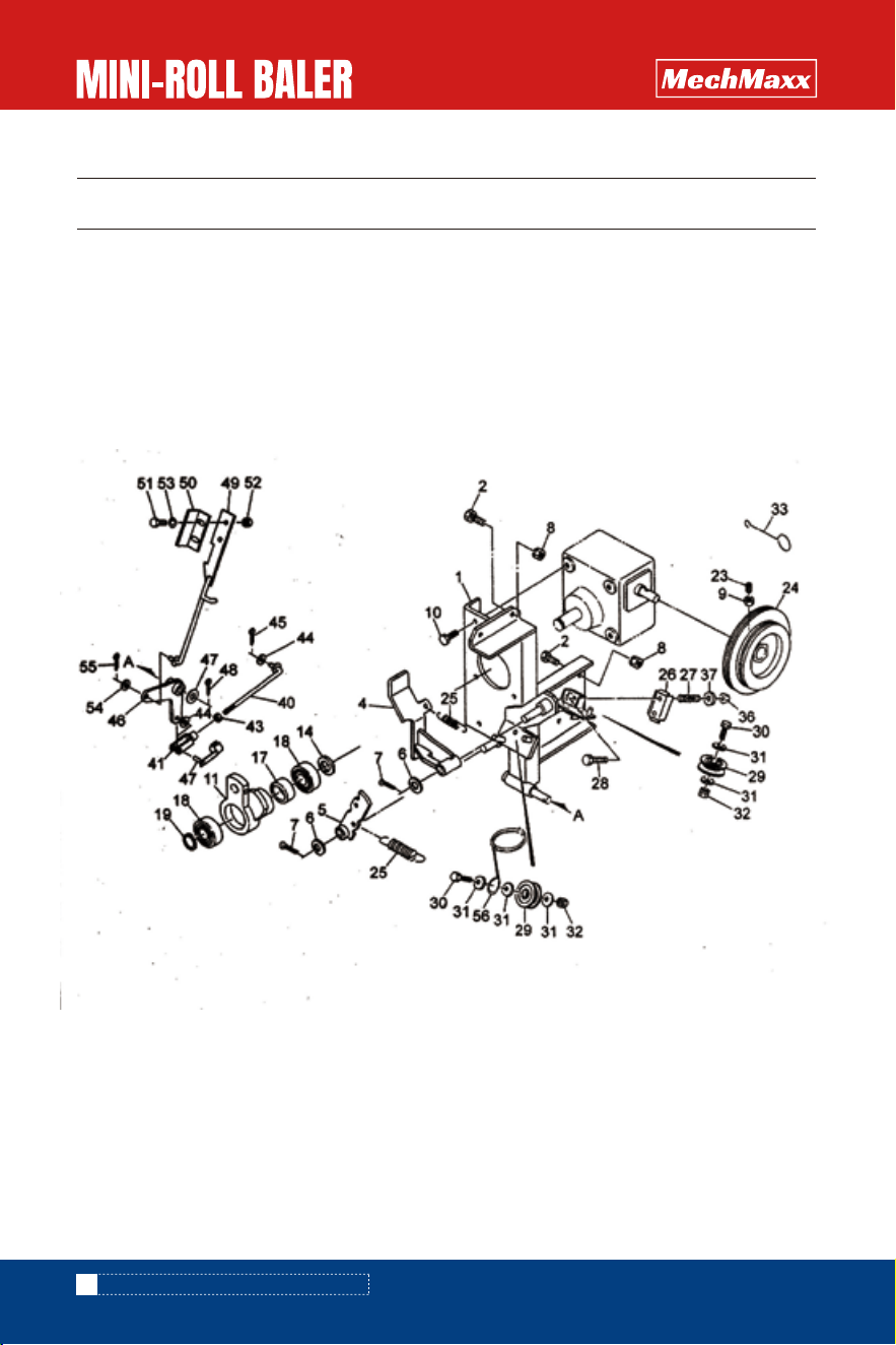
PARTS DIAGRAM(Picking-up sprocket Assy)
PARTS DIAGRAM(PICKING-UP SPROCKET ASSY

42
www.mechmaxx.com
1
1
3
1
1
1
1
4
4
1
2
1
1
2
1
2
1
1
2
1
1
1
1
1
1
1
1
2
1
No. Drawing No. QTY
1
2
3
4
5
6
7
8
9
10
11
12
13
14
15
16
17
18
19
20
21
22
23
24
25
26
27
28
29
HB3210.6-01-00
HB3210.6-02
GB7810-87
HB3210.6-18
HB3210.6-03
GB5786-86
HB3210.6-04
GB97.1-85
GB5786-86
GB91-87
GB860-87
GB/T 7813-1998
GB7810-87
GB5786-86
HB3210.6-05
HB3210.6-06
HB3210.6-07
HB3210.6-08
HB3210.6-09
HB3210.4-04
GB/T13680-1992
HB3210.6-11
GB5786-86
GB860-87
GB/T1243-2006
GB/T 7813-1998
GB7810-87
DESCRIPTION
Sprocket cover CP
Dust cover
Plum-shaped bolt M8×14
bearing CS204-2RS
Bearing cover
Bearing seat PFL204
Tension disc
Bolt Ml0×65 (8.8)
spring
slotted nut M20×1.5 GB9457
Bolt M8×25 (8.8)
Split pin 4×25
washer;20
Bearing seat PFL205
Spherical ball bearings CS205-2RS
Bolt M10X20 (8.8)
Friction disc
bush
Friction washer
sprocket;RS50×18T
sprocket;RS50×32T
Pulley CP
Square nut
bush
Bolt Ml0x40 (8.8)
washer;12
chain10A-59×l
Bearing seat PF206
Bearing CS206-2RS
PARTS LIST(Picking-up sprocket Assy)
PARTS LIST(PICKING-UP SPROCKET ASSY
43
www.mechmaxx.com
3
1
1
1
1
1
1
1
1
1
2
1
2
2
6
1
1
1
1
2
4
4
1
4
1
1
2
2
3
No. Drawing No. DESCRIPTION QTY
30
31
32
33
34
35
36
37
38
39
40
41
42
43
44
45
46
47
48
49
50
51
52
53
54
56
57
58
59
Bolt Ml0×20 (8.8)
Bolt M12×45 (8.8)
Up-down Rod CP
Brake plate
Pull rod RXHB3120
fork;10×40
pin;10×40
Split pin 3.2×16
Bolt Ml0×30(8.8)
Nylon locking nut Ml0
Disc washer 10
Handle sleeve;12
Extension spring:H
Adjustable screw;Ml0
Nut Ml0 (8.8)
Flat washer 10
Elbow bend (optional) CP;R
Elbow bend (optional) CP:L
Shield(optional)
9 Pin(optional) 8×1.6
Square neck boltM8×15 (optional)
Nut(optional) M8
Washer 21×1.5
washer ;10
Joint 10A
Coupling part 10A
Spring washer 10
Spring washer12
Spring washer 10
GB5786-86
GB5786-86
HB3210.6-12
HB3210.6-13
HB3210.6-14
HB3210.6-15
GB882-86
GB91-87
GB5786-86
GB/T3098.9-2002
JB/ZQ 4340-2006
HB3210.6-10
HB3210.6-17
GB6710-86
GB97.1-85
GB6710-86
GB860-87
GB860-87
GB93-87
GB93-87
GB93-87
PARTS LIST(PICKING-UP SPROCKET ASSY)
44
www.mechmaxx.com
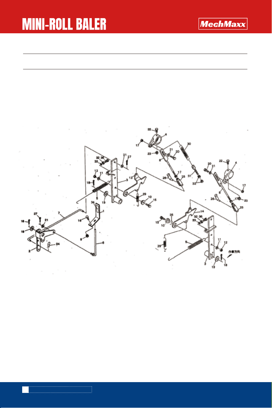
PARTS DIAGRAM(Twine binding bracket Assy)
PARTS DIAGRAM(TWINE BINDING BRACKET ASSY)

45
www.mechmaxx.com
1
6
1
1
2
2
6
1
4
1
1
1
2
1
1
1
2
1
2
2
2
2
5
2
1
2
2
1
1
No. Drawing No. QTY
1
2
4
5
6
7
8
9
10
11
14
17
18
19
23
24
25
26
27
28
29
30
31
32
33
36
37
40
41
HB3210.7-01-00
GB5786-86
HB3210.7-02-00
HB3210.7-03
GB97.1-85
GB91-87
GB6710-86
GB6710-86
GB5786-86
HB3210.7-04
HB3210.7-05
GB/T290-98
GB297-84
GB484.1-86
GB/T 80-2000
HB3210.7-06
HB3210.7-07
HB3210.7-08
HB3210.7-09
GB5786-86
HB3210.7-10
GB5786-86
GB97.1-85
GB6710-86
HB3210.7-11
GB/T3098.9-2002
GB97.1-85
HB3210.7-12
HB3210.7-13
DESCRIPTION
Twine clip plate CP;1
Bolt M8×20 (8.8)
Pressure plate CP
Tension plate CP
Washer 12
Split pin 3.2×16
Nut M8
Bolt M8×20
cam
Retaining ring 25
Single-direction
Rolling bearing HK2520(25×32×20)
bearing 6005-2RS (25X47X12)
Shaft spring retaining ring 25
Hexagon socket set screw M8×20
Twine pulley HB3120
Pull spring
slot plate
compression spring
boltM6×50
pulleyCP
boltM8×30 (8.8)
Flat washer 8
nut M8
Twine hook
Nylon locking nut M6
Flat washer 6
Adjustable lever CP
Fork 8×32
PARTS LIST(Twine binding bracket Assy)
PARTS LIST(TWINE BINDING BRACKET ASSY)
46
www.mechmaxx.com
1
1
2
1
1
1
1
1
1
2
2
2
1
1
1
No. Drawing No. QTY
42
43
44
45
46
47
48
49
50
51
52
53
54
55
56
HB3210.7-14
GB6710-86
GB97.1-85
GB91-87
HB3210.7-15
GB97.1-85
GB91-87
HB3210.7-16
HB3210.7-17
GB5786-86
GB6710-86
GB97.1-85
GB97.1-85
GB91-87
HB3210.7-18
DESCRIPTION
Pin 8×30
nutM8
Washer 8
Split pin 3.2×16
Fork rod CP
Flat washer 12
Split pin 3.2×16
Spring rod CP
pressure pad
Bolt M6×20
Nut M6
Flat washer 6
Flat washer 8
Split pin 3.2×16
Twine ring
PARTS LIST(TWINE BINDING BRACKET ASSY)
47
www.mechmaxx.com
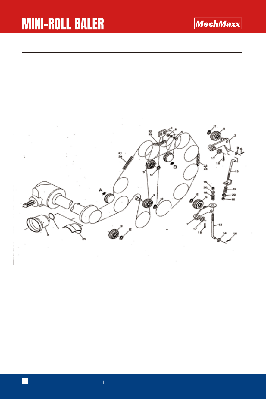
PARTS DIAGRAM(Twine binding support Assy)
PARTS DIAGRAM(TWINE BINDING SUPPORT ASSY)
48
www.mechmaxx.com
1
2
2
2
1
1
1
1
1
1
2
1
1
2
2
1
1
1
1
1
1
5
1
1
3
2
1
1
4
No. Drawing No. QTY
1
2
3
4
5
6
7
8
9
10
11
12
13
14
15
16
17
18
19
20
21
22
23
24
25
26
27
28
29
HB3210.8-01-00
GB5786-86
GB6710-86
GB5786-86
HB3210.8-02-00
HB3210.8-03
HB3210.8-04
HB3210.8-05
GB5786-86
GB6710-86
GB93-87
HB3210.8-06-00
GB119-86
GB1152×79
GB97.1-85
GB879-86
GB894.1-86
GB97.1-85
HB3210.8-08-00
HB3210.8-09-00
HB3210.8-10-00
HB3210.8-11
HB3210.8-12
HB3210.8-13-00
JB/ZQ4340-2006
GB6710-86
GB97.1-85
GB879-86
GB97.1-85
DESCRIPTION
Support rod CP;2
Bolt M8×20 (8.8)
Nut M8
bolt M8×20 (8.8)
Rubber racket CP
rubber washer
bush
sleeve
bolt M8×80 (8.8)
nut M8 (8.8)
Spring washer 8
Swing arm CP
Cylindrical pin
Grease nipple AM6×1
Flat washer 6
Spring cylindrical pin 6×36
Shaft spring retaining ring 15
washer 17×1.5
Support rod CP;1
bracket
Support rod
Nylon sleeve
Torsion spring
Pulley bracket CP:3
Spring disc washer
nut M8 (8.8)
Flat washer 17×1.5
Spring cylindrical pin 5×32
Flat washer 8
PARTS LIST(Twine binding support Assy)
PARTS LIST(TWINE BINDING SUPPORT ASSY)
49
www.mechmaxx.com
4
1
1
1
1
1
1
2
1
1
2
1
1
1
1
1
1
1
1
1
1
2
3
1
1
1
1
1
1
GB5786-86
GB1152×79
GB1152×79
GB879-86
HB3210.8-15
HB3210.8-16
HB3210.8-07
GB6710-86
HB3210.8-17-00
HB3210.8-18
HB3210.7-10
GB97.1-85
HB3210.8-19-00
HB3210.8-14
GB/T3098.9-2002
GB/T 5280-2002
GB5786-86
GB97.1-85
HB3210.8-20
HB3210.8-21
GB 819-1985
GB/T3098.9-2002
GB/T3098.9-2002
HB3210.8-22
HB3210.8-22
GB5786-86
GB6710-86
GB97.1-85
No. Drawing No.
bolt M8×20 (8.8)
grease nipple ONA6 M6×1
grease nipple ONA6 M6×1
Spring cylindrical pin 6×36
Extension spring;H
Extension spring;H
screw:M8
nut M8 (8.8)
Slot pressure pad
compression spring ;A
pulleyCP
Flat washer 8
Opening retaining ring 5
Knife bracket
knife
Nylon locking nut M8
Self-tapping screw M3×6
bolt M8×20 (8.8)
Washer 8
Rubber washer
Nylon washer
Cross Countersunk head screw
Nylon locking nut M8
Nylon locking nut M6
plate
Plate HB3120
bolt M8X16 (8.8) HB3120
nut M8(8.8) HB3120
Flat washer 16
DESCRIPTION QTY
30
31
32
33
34
35
36
37
38
39
40
41
42
43
44
45
46
47
48
49
50
51
52
53
54
55
56
57
58
PARTS LIST(TWINE BINDING SUPPORT ASSY)
50
www.mechmaxx.com
No. Drawing No. QTY
61
62
63
64
65
66
HB3210.8-23
GB5786-86
GBT 818-2000
GB6710-86
GB97.1-85
DESCRIPTION
buzzer switch racket
bolt M8×20 (8.8)
switch
Cross crew M4×30
nut M4 (8.8)
Flat washer: 4
1
2
1
2
2
2
PARTS DIAGRAM(Reducer assy)
PARTS DIAGRAM(REDUCER ASSY)
51
www.mechmaxx.com
1
1
2
2
1
1
1
1
1
1
1
1
1
1
4
1
1
1
4
No. Drawing No. QTY
1
2
3
4
5
6
7
8
9
10
11
12
13
14
15
16
17
18
19
HB3210.9-01
GBT 9877-2008
GB893.1-86
GB297-84
HB3210.9-02
HB321009-03
HB3210.8-04
GB297-84
GB297-84
D30507
GB893.1-86
GB1096-79
HB3210.9-05
HB3210.9-06
GB5786-86
HB3210.9-07
HB3210.9-08
GB3452.1-82
GB93-87
DESCRIPTION
worm
Lip seal FB15×35×8
Holes Circlips 35
Bearing 6202
Sealing cover KRCA3507
Wormgear
Worm-wheel shaft
Bearing 6203
Ball bearing 6005-2RS
Oil seal FB30×50×7
Retaining ring 47
Flat key 5×5×25
cover
case
Bolt M6×16 (8.8)
Oil port bolt
Rubber washer
O-rubber seal G-60
Spring washer 6
PARTS LIST(Reducer assy)
PARTS LIST(REDUCER ASSY)
52
www.mechmaxx.com
PARTS DIAGRAM(Topper cover rod)
PARTS DIAGRAM(TOPPER COVER ROD)
1
1
1
5
5
1
1
1
1
3
11
22
22
4
24
24
24
4
4
1
8
2
4
2
8
12
1
1
1
No. Drawing No. QTY
1
2
3
4
5
6
7
8
9
10
11
12
13
14
15
16
17
18
19
20
21
22
23
24
25
26
27
29
30
HB3210.10-01
HB3210.10-02
HB3210.10-03-00
HB3210.10-04
HB3210.10-05
HB3210.10-06-00
HB3210.10-07
HB3210.10-08-00
GB6710-86
HB3210.10-09
GB93-87
GB6710-86
HB3210.10-10
HB3210.10-11
GB5786-86
GB5786-86
GB6710-86
GB91-87
GB97.1-85
GB5786-86
GB97.1-85
GB5786-86
GB/T3098.9-2002
HB3210.7-13
HB3210.7-14
GB91-87
HB3210.10-12
HB3210.10-13
DESCRIPTION
Indicator board
Fork plate
Connecting plate
Topper cover
extension spring HB3120
Indicator rod HB3120
Pull rod HB3120
Connecting rod HB3120
nut M8
Shaft sleeve
Spring washer 10
nut 10
hook ;R
hook:L
Bolt Ml0×35 (8.8)
bolt Ml0×20 (8.8)
nutM8 (8)
Split pin3.2×32
21×1.5 washer
Bolt M8×25 (8.8)
washer 8
bolt M8×75 (8.8)
Nylon locking nut M8
B-pin 8×1.6
Connecting yoke;8×32
Connecting pin;8×32
Split pin3.2×16
Extension Spring;2.3×1 8×6 8
Extension Spring;H
53
www.mechmaxx.com
PARTS LIST(Topper cover rod)
PARTS LIST(TOPPER COVER ROD)
4
2
3
2
1
1
No. Drawing No. QTY
31
32
33
34
35
36
HB3210.10-14
GB6710-86
GB93-87
HB3210.10-15
GB5786-86
DESCRIPTION
Pull rod;Ml 0
nut Ml0 (8)
washer 10
sticker
Adjusting shimΦ10.5×0.27
Bolt Ml0×35 (8.8)
54
www.mechmaxx.com
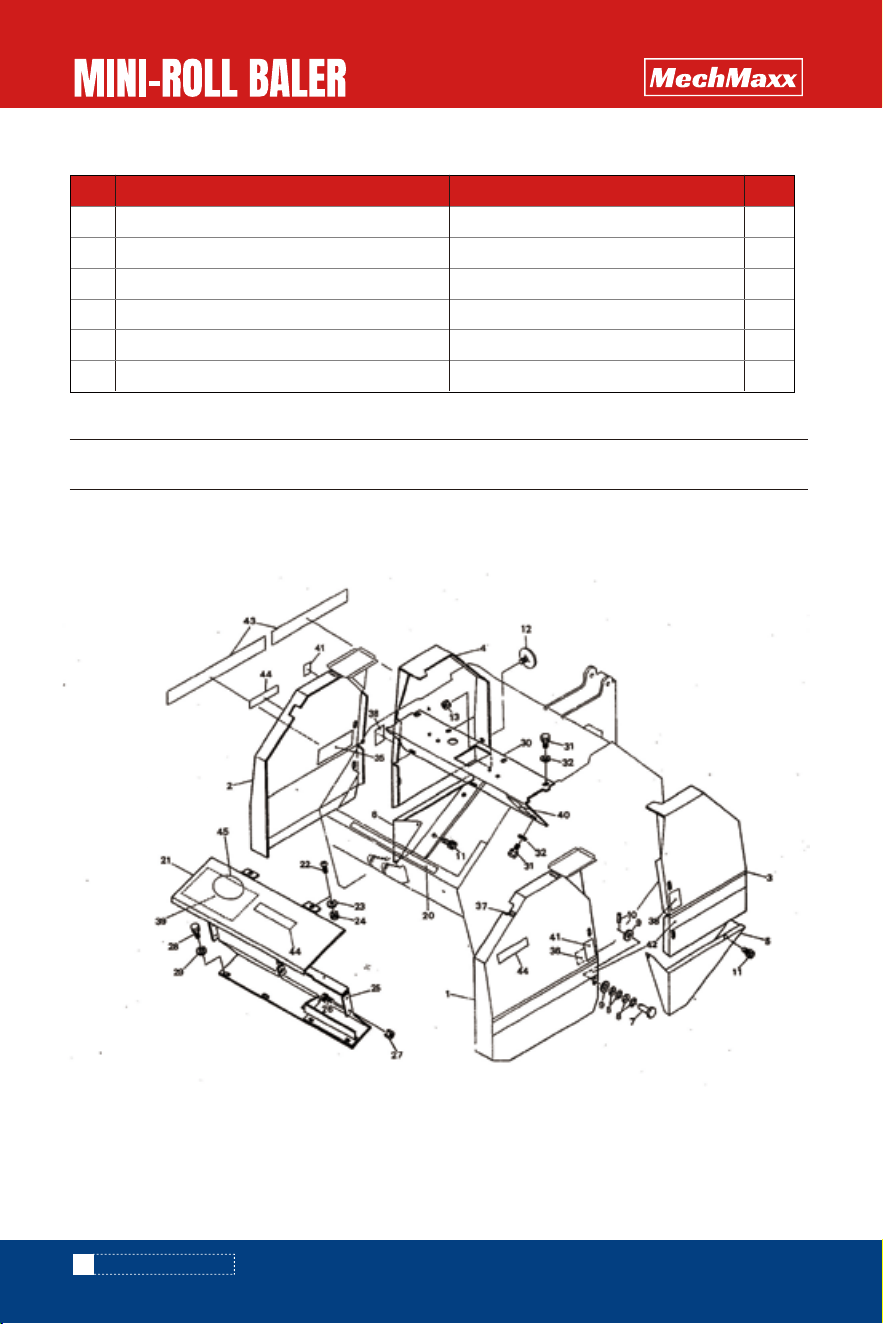
PARTS DIAGRAM(Cover)
PARTS DIAGRAM(COVER)
55
www.mechmaxx.com
1
1
1
1
1
1
8
32
16
8
4
2
2
1
1
2
2
2
1
4
4
4
4
1
8
8
1
1
1
No. Drawing No. QTY
1
2
3
4
5
6
7
8
9
10
11
12
13
20
21
22
23
24
25
26
27
28
29
30
31
32
35
36
37
HB3210.11-01-00
HB3210.11-02-00
HB3210.11-03-00
HB3210.11-04-00
HB3210.11-05-00
HB3210.11-06-00
HB3210.11-07
JB/ZQ4340-2006
GB97.1-85
GB879-86
GB5786-86
HB3210.11-08
GB6710-86
HB3210.11-09
HB3210.11-10-00
GBT 818-2000
GB97.1-85
GB6710-86
HB3210.11-11-00
GB5786-86
GB6710-86
GB5786-86
GB97.1-85
HB3210.11-12-00
GB5786-86
GB97.1-85
HB3210.11-13
HB3210.11-14
HB3210.11-15
DESCRIPTION
Front cover housing CP;L HB3120
Front cover housing CP;R HB3120
rear cover housing CP;L HB3120
rear cover housing CP;R HB3120
Cover housing CP;L HB3120
Cover housing CP; HB3120
Star handle :50
Disc spring washer
Flat washer 8
Spring cylindrical pin 4×16
Bolt M8×16 (8.8)
reflector;R-80CI
Nut M5
magnet
gate; CP HB3120
cross head screw M6×12
Washer 6
Nut M6
Cover box CP HB3120
bolt M8×20 (8.8)
nut M8
bolt M8×20 (8.8)
Flat washer 8
Cover housing;CP HB3120
bolt M8×20 (8.8)
Flat washer8
sticker
sticker
sticker
PARTS LIST(Cover)
PARTS LIST(COVER)
56
www.mechmaxx.com
2
1
1
2
1
1
3
1
1
No. Drawing No. QTY
38
39
40
41
42
43
44
45
46
HB3210.11-16
HB3210.11-17
HB3210.11-18
HB3210.11-19
HB3210.11-20
HB3210.11-21
HB3210.11-22
HB3210.11-23
HB3210.11-24
DESCRIPTION
Warning sticker
sticker
Warning sticker
Warning sticker
Warning sticker ;850L HB3120
Warning sticker ;850R HB3120
Name of manufacturer
sticker
sticker
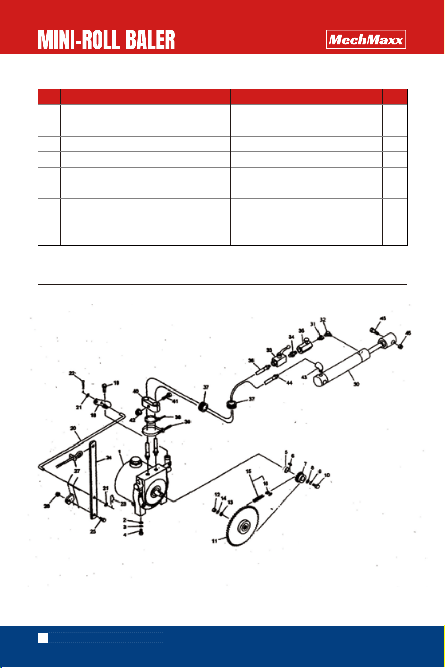
PARTS DIAGRAM(Hydraulic pump assy)
PARTS DIAGRAM(HYDRAULIC PUMP ASSY)
57
www.mechmaxx.com
1
2
2
2
1
1
1
1
1
1
1
1
1
1
1
1
1
1
1
2
1
1
1
1
1
1
1
1
1
REF DESCRIPTION QTY
1
2
3
4
5
6
7
8
9
10
11
12
13
14
15
16
18
19
20
21
22
23
24
25
26
27
30
31
32
HB3210.12-04-00
GB97.1-85
GB93-87
GB5786-86
HB3210.12-01
GB1096-79
HB3210.12-02
GB97.1-85
GB93-87
GB5786-86
HB3210.12-03
GB6710-86
GB97.1-85
GB93-87
GB/T1243-2006
GB/T1243-2006
HB3210.12-05
GB5786-86
HB3210.12-06
GB97.1-85
GB91-87
HB3210.12-07
GB5786-86
GB/T3098.9-2002
HB3210.12-08
HB3210.12-09-00
DESCRIPTION
Hydraulic pump station ;95R
Washer 10
Spring wahser 10
boltMl0×25 (8,8)
Check sleeve
Flat key5×5×20(B type)
Small pulley 9T
Washer 6
Spring washer 6
bolt M6×16 (8,8)
Large pulley 43T
nutM12 (8.8)
washer:13×4.5
Spring washer 12
chain08A-56×1
Chain joint 08A
Conneting board
Bolt M8×16 (8.8)
Connecting rod
Washer 8
Split pin 3.2×16
Β-pin 8×1.6
plate
bolt M8×25 (8.8)
Nylon locking nut M8
Nylon rope 6×3500
Cylinder CSH35×210×375
Conical female and male outside coupler Gl/4×Rl/4
90°conical male inside coupler Gl/4×Rl/4
PARTS LIST(Hydraulic pump assy)
PARTS LIST(HYDRAULIC PUMP ASSY)

58
www.mechmaxx.com
1
1
1
2
2
3
2
4
2
2
2
REF DESCRIPTION DESCRIPTION QTY
33
34
35
36
37
38
39
43
44
45
46
Control volve Rcl/4
male coupler R1/4
Single-direction throttle valve Rcl/4
Rubber hose Gl/4×1000
bush;Φ35
Plastic hoop 2.5×100
Plastic hoop 4.8×251
90°conical male inside coupler Gl/4×Rl/4
90°female coupler Gl/4
bolt M16×80 (8.8)
Nylon locking nut M6
GB/T12223-2005
GB/T8100-1987
GB/T1277-99
HB3210.12-10
GB5786-86
GB/T3098.9-2002
PARTS LIST(HYDRAULIC PUMP ASSY)