Maxxyz Wing &
Playback Module
Installation Note
© 2005 Martin Professional A/S, Denmark.
All rights reserved. No part of this document may be reproduced, in any form or by any means, without permission in writing from
Martin Professional A/S, Denmark. Printed in Denmark.
P/N 35000568, Rev. A

2 Maxxyz Wing Installation Note
I
NTRODUCTION
Thank you for selecting the Martin Maxxyz Playback Wing.
The Maxxyz Playback Wing is an extension to the Maxxyz console that consists of either one or
two Maxxyz Playback Module(s) and a Maxxyz Wing Frame. Each Maxxyz Playback Module
provides 10 playback faders. Each optional Maxxyz Wing Frame accommodates up to two
Playback Modules.
This manual matches the functionality provided in Version 1.3.78 of the Maxxyz software. For the
latest firmware and software updates, documentation, and other information about this console,
please visit www.maxxyz.com.
Technical Support
For a complete list of Technical Support phone numbers, please visit our web site at http://
www.martin.com/service/hotline.asp
Maxxyz Safety Information
This product presents risks of lethal or severe injury due to electric shock. Read this Installation
Note before powering or installing the console, follow the safety precautions listed below and
observe all warnings in this manual and printed on the console. If you have questions about how to
operate the console safely, please contact your Martin dealer or call the Martin 24-hour service hot
line at +45 70 200 201 or +1 954 858 1800.
• Always ground (earth) the device electrically.
• Use only a source of AC power that complies with local building and electrical codes and has
both overload and ground-fault protection.
• Do not expose the device to rain or moisture.
• Refer any service operation not described in this manual to a qualified technician.
• Do not modify the device or install other than genuine Martin parts.
Power Connection
You may need to install a cord cap that fits your supply on the power cable. A 3-prong grounding-
type plug must be installed following the manufacturer’s instructions. The table below shows some
possible pin identification schemes; if the pins are not clearly identified, or if you have any doubts
about proper installation, consult a qualified electrician.
Wire Color Pin Symbol Screw (US)
brown live L yellow or brass
blue neutral N silver
yellow/green ground green

Maxxyz Wing Installation Note 3
Included Items
Each Maxxyz Playback Module (part number 90732100) contains the following items:
• Playback Module
• 6.3 AT fuse (installed) for use with AC supplies of 200 - 250 volts
• IEC Power cable
• IEC Extension cable
• Ethercon network cable
•Desk lamp
• USB cable
Each Maxxyz Wing Frame (part number 90732110) contains the following items:
• Road case
• Wing Frame with attached Ethercon and Power interconnect cables
•Desk lamp
• Ethercon network cable
• Two spindles for attaching Wing Frame to Maxxyz console
S
ET
U
P
/A
SSEMBLY
There are two different methods of setting up the playback modules; one for “stand alone” use and
one for mounting in the Wing Frame. In most cases, a single module will be used in the “stand
alone” mode, while the Wing Frame will be used with two modules.
Single Playback Module
A Maxxyz module ships with protective side plates attached to each side. These plates support the
faceplate and prevent cosmetic damage to the module. Aside from connection to the console, the
module is “ready to use” as soon as it’s removed from the box.
Module Use with Wing Frame
1. Remove the Playback Module(s) and Wing Frame from their packing materials.
2. Using a 4mm allen wrench, remove the three screws that attach the side plates to each side of
the module.
3. Insert a module into the lower of the two mounting apertures in the wing frame.
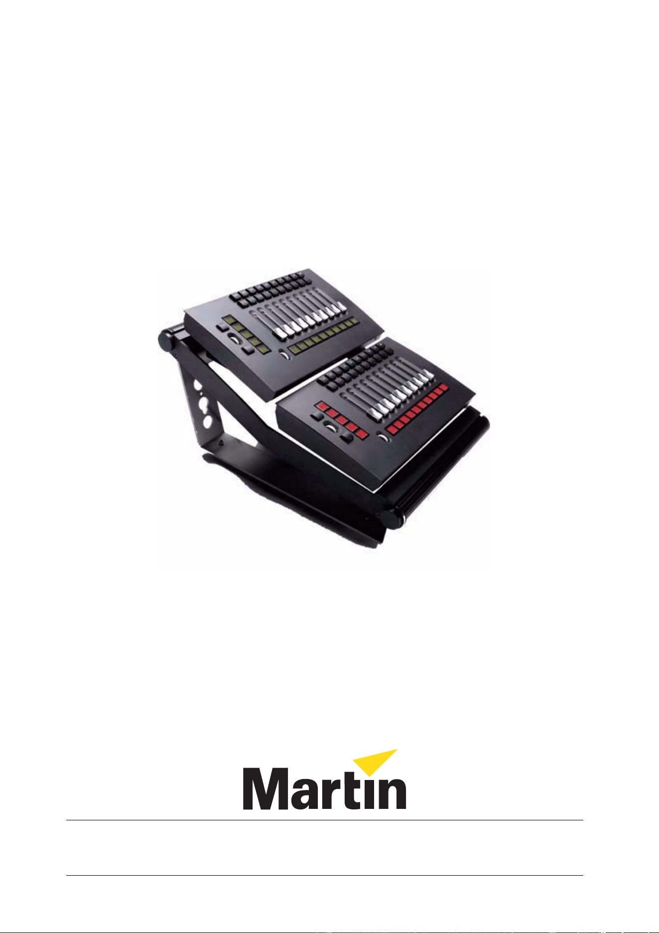
4. Gently roll the frame and module onto one side.
4 Maxxyz Wing Installation Note
5. Align the module with the quarter-turn screws (illustrated below) in the frame, and attach the
module to the frame by turning the screws one full quarter-turn clockwise until they lock.
6. Connect the IEC power cable to the “Mains In” connector.
7. Connect the Ethercon network cable to the “Wing In” connector.
8. Repeat steps 2. to 4. to insert a module into the top opening.
9. Connect the IEC power cable to the “Mains Out” connector of the top module.
10. Connect the Ethercon network cable to the “Wing Out” connector of the top module.
11. Attach the desk lamp to the connector labeled “Lamp” on the back of the top module.
These steps can also be followed for connecting two modules that are not mounted in a Wing
Frame. Further, it is possible to connect one wing to another wing by going from the “Wing Out”
connector on the bottom module of the first wing to the “Wing In” connector on the top module of
the second wing. In no case may the number of modules on a given link exceed four and no cable
may exceed 5 meters.
Maxxyz Wing Installation Note 5
C
ONNECTIONS
AND
C
ONFIGURATION
Connections
Connections for either an individual Playback Module or a Wing Frame are simple and similar.
1. Connect an Ethercon network cable to the “Wing In” port on the back of the module. If you are
using the Wing Frame, use the “Wing In” port on the top module.
2. Connect the other end of the Ethercon cable to either “Wing 1,” “Wing 2,” “Wing 3,” or “Wing 4”
on the back of the Maxxyz console. It doesn’t matter which port you use.
3. Connect the IEC cable to the “Mains In” connector on the back of the module and plug the
other end to your mains power supply. If you are using the Wing Frame, use the “Mains In” on
the top module.
While it is possible to use the Wing Frame standing separately from the Maxxyz console, it is also
possible to connect the Wing Frame directly to the Maxxyz console.
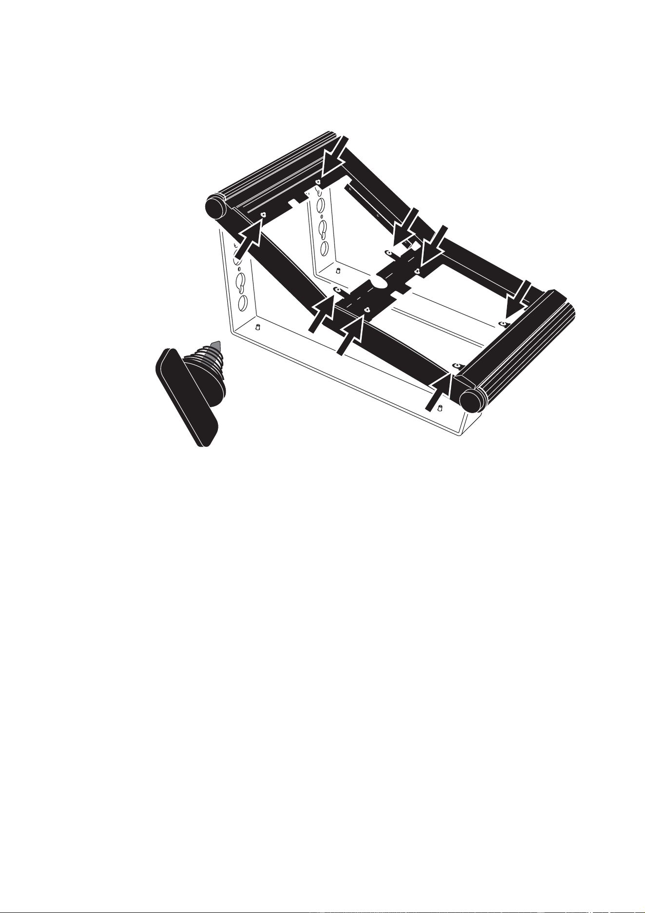
1 DIP Switch Address (see below for settings)
2 Wireless Remote (reserved for future use)
3 USB In (reserved for future use with Maxxyz PC)
4 Wing In Ethercon connector
5 Wing Out Ethercon connector
6 USB Out (reserved for future use with Maxxyz PC)
7 Desk Lamp connector
8 Mains In
9 Mains Out
WIRELESS
REMOTE
ADDRESS
USB
IN OUT
USB
WING
OUTIN
LAMP MAINS
IN OUT
90-250VAC ~, 50-60 Hz
90-250VAC ~, 50-60 Hz
90-250VAC ~, MAX 2.5A
90-250VAC ~, MAX 2.5A
1 2 3 4 5 6 7 8 9
6 Maxxyz Wing Installation Note
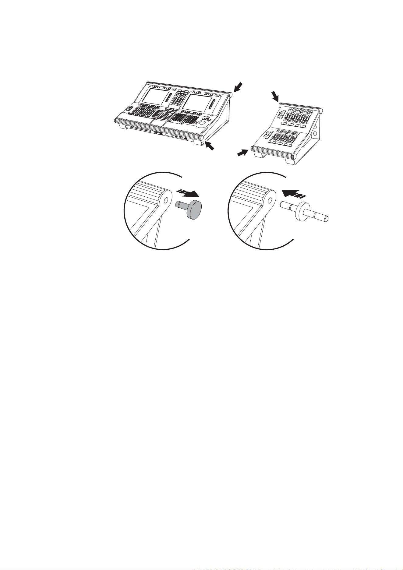
4. Remove the top and bottom end caps from either the left or right side of the Wing Frame.
5. Remove the top and bottom end caps from the opposite side of the Maxxyz console.
6. Place the spindles provided with the Wing Frame into the holes formerly occupied by the end
caps in the Wing Frame.
7. On a level surface, slide the Wing Frame with attached spindles into the end cap holes on the
Maxxyz console.
It is also possible to connect multiple Wing Frames together in this manner.
After connecting the Wing Frame to the Maxxyz console, it may be convenient to move the monitor
bracket from the console to the Wing Frame.
If you wish to hinge the Maxxyz console up, or for transport purposes, it may be more convenient
to temporarily disconnect and detach the Wing Frame.

Maxxyz Wing Installation Note 7
Configuration
It is possible to connect up to sixteen (16) modules (or eight fully populated Wing Frames) to a
Maxxyz console. No more than four modules may be connected to any given wing port found on
the back of the console and every module must have a unique ID. These IDs are set using the DIP
switches found on the back of the module. The table below shows the appropriate settings for
each module.
A DIP switch pin in the down position is “on.”
Software
The Maxxyz Playback Module requires connection to a Maxxyz console running version 1.3.78 or
higher. It is recommended that when the wing is first installed, that it be powered before the
Maxxyz console is started. In this way, it is assured that the proper software and drivers will be
automatically loaded.
Module # PIN 1 PIN 2 PIN 3 PIN 4 PIN 5 PIN 6
1 Off Off Off Off Off Off
2OnOff Off Off Off Off
3 Off On Off Off Off Off
4OnOnOff Off Off Off
5 Off Off On Off Off Off
6OnOff On Off Off Off
7 Off On On Off Off Off
8 OnOnOnOff Off Off
9 Off Off Off On Off Off
10 On Off Off On Off Off
11 Off On Off On Off Off
12 On On Off On Off Off
13 Off Off On On Off Off
14 On Off On On Off Off
15 Off On On On Off Off
16 On On On On Off Off
8 Maxxyz Wing Installation Note
C
ONTROLS
The majority of the functionality of the Playback Module is covered in
the Maxxyz User Manual in the chapter “Working with Cues” under the
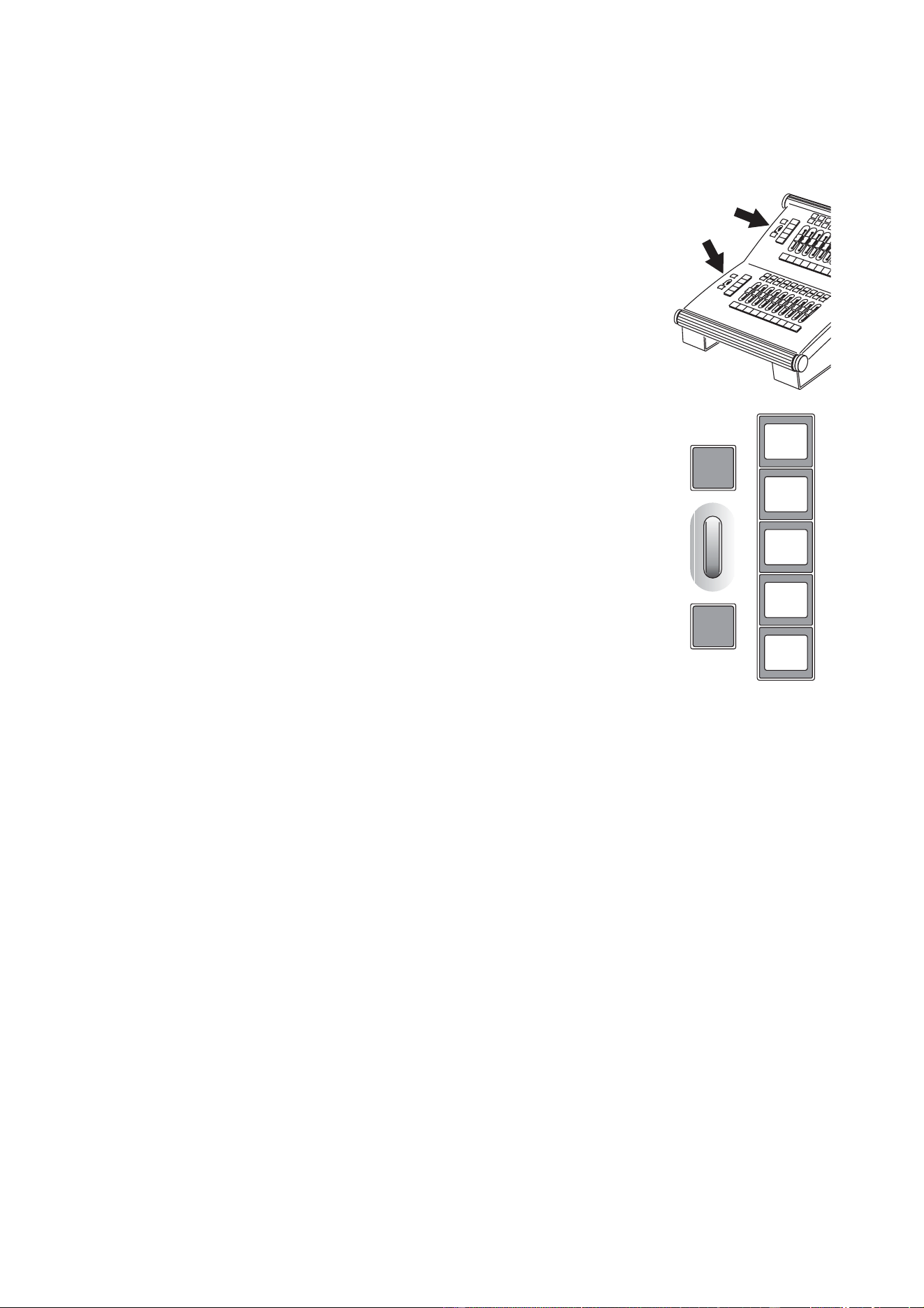
heading “Playback Controls.” However, to the left side of the module are
5 LCDs, one jog wheel and two buttons that have specific functions.
LCD Keys
The LCD keys on the Playback Module are used for selecting the Bank
you are working from. To load a bank, press the desired key. Note that
when you press a key to select a bank, that bank will then be loaded to
the center LCD key and the other LCDs will increment or decrement
accordingly.
Jog Wheel
The silver jog wheel is used to scroll up and down the bank selections.
Rolling the jog wheel up (away from you) will increment the banks
displayed in the LCDs by one. Rolling the jog wheel down will
decrement the display by one.
Buttons
Above and below the jog wheel are two buttons. Pressing the top button
will cause the banks displayed in the LCDs to increment by five while
pressing the bottom button will cause the LCDs to decrement by five.
S
ERVICE
The Maxxyz module is designed as a rugged, roadworthy device. Occasional cleaning is the only
service required of the user. For any other service-related concerns, please contact your Martin
dealer or visit www.martin.com.
Any service not described in this installation note must be carried out by a qualified Martin
technician
Cleaning
The Maxxyz module requires periodic cleaning, as does any computer. The schedule depends
heavily on the operating environment; please consult a Martin service technician for
recommendations if needed.
As with any computer, never spray the cleaner directly onto the module, always spray onto a lint-
free cloth and wipe clean.
Important! Excessive dust and smoke fluid buildup can degrade performance and cause
overheating and damage to the module that is not covered by the warranty.
