
Operator’s Manual
www.mechmaxx.com
WARRANTY


TABLE OF CONTENTS
TABLE OF CONTENTS
IMPORTANT SAFETY INFORMATION
1
SAFETY ALWAYS
TRANSPORT MACHINERY SAFELY
2
2
USING THIS MANUAL
5
TERMINOLOGY
5
OWNER ASSISTANCE
5
LEVELING THE MOWER
16
CUTTING HEIGHT ADJUSTMENT
16
3-POINT HITCH ADJUSTMENTS
16
MUST ADD OIL BEFORE FIRST USE
15
TRANSPORTING
15
MOWING INSTRUCTIONS
15
OPERATING INSTRUCTIONS
15
BELT TENSION
16
MAINTENANCE
17
KNIFE REPLACEMENT
17
V-BELT INSTALLATION
17
STORAGE
17
LUBRICATION
17
WARRANTY
21
BOLT TORQUE
21
ENGLISH TORQUE SPECIFICATIONS
21
METRIC TORQUE SPECIFICATIONS
21
TRACTOR REQUIREMENTS
6
PACKING DESCRIPTION
6
INSTALLATION WIZARD
10
TRACTOR HOOK-UP
13
DRIVELINE INSTALLATION
14
2
SAFETY LABELS
4
INTRODUCTION
5
6
16
ASSEMBLY AND SET-UP
ADJUSTMENTS
17
MAINTENANCE AND LUBRICATION
15
OPERATING INSTRUCTIONS
19
SPECIFICATIONS & CAPACITIES
20
TROUBLESHOOTING
21
APPENDIX
22
PART BREAKDOWN LIST
24
PARTS LIST
1
www.mechmaxx.com
TABLE OF CONTENTS

SAFETY ALWAYS
TRANSPORT MACHINERY SAFELY
2
www.mechmaxx.com
IMPORTANT SAFETY INFORMATION
IMPORTANT SAFETY INFORMATION
Thoroughly read and understand the instructions given in
this manual before operation. Refer to the “Safety Decal”,
read all instructions noted on them.
Do not allow anyone to operate this equipment who has
not fully read and comprehended this manual and who has
not been properly trained in the safe operation of the
equipment.
1. Operator should be familiar with all functions of the
unit. Operate implement from the driver’s seat only.
2. Make sure all guards and shields are in place and
secured before operating the implement.
3. Do not leave tractor or implement unattended with
engine running.
4. Dismounting from a moving tractor could cause serious
injury or death.
5. Do not stand between tractor and implement during
hitching.
6. Keep hands, feet, and clothing away from power-driven
parts.
7. Wear snug fitting clothing to avoid entanglement with
moving parts.
8. Watch out for wires, trees, etc., when raising imple-
ment. Make sure all persons are clear of working area.
9. Turning tractor too tight may cause implement to ride
up on wheels. This could result in injury or equipment
damage.
Look For the Safety Alert Symbol
The SAFETY ALERT SYMBOL indicates there is a potential
hazard to personal safety involved and extra safety
precaution must be taken. When you see this symbol, be
alert and carefully read the message that followsit. In
addition to design and configuration of equipment, hazard
controland accident prevention are dependent upon the
awareness, concern, prudence, and proper training of
personnel involved in the operation, transport, mainte-
nance and storage of equipment.
Be aware of signal words
A signal word designates a degree or level of hazard
seriousness. The signal words are:
For you protection
Thoroughly read and understand the “safety label”
section, read all instructions noted on them.
Shut down and storage
Lower machine to ground, put tractor in park, turn off
engine, and remove the ignition key.
Detach and store implements in an area where children
normally do not play. Secure implement by using blocks
and supports.
Use safety lights and devices
Slow moving tractors, self-propelled equipment, and
towed implements can create a hazard when driven on
public roads. They are difficult to see, especially at night.
Flashing warning lights and turn signals are recommend-
ed whenever driving on public roads. Use lights and devic-
es provided with implement.
1. Comply with state and local laws.
2. Maximum transport speed for implement is 20 mph. Do
not exceed. Never travel at a speed which does not allow
adequate control of steering and stopping. Some rough
terrain requires a slower speed.
Indicates an imminently hazardous situa-
tion which, if not avoids, will result in
death or serious injury. This signal word is
limited to the most extreme situations,
typically for machine components that,
for functional purpose, cannot be guard-
ed.
DANGER
Indicates a potentially hazardous situa-
tion which, if not avoided, could result in
death or serious injury, and includes
hazards that are exposed when guards are
removed. It may also be used to alert
against unsafe practices.
WARNING
Indicates a potentially hazardous situa-
tion which, if not avoided, may result in
minor or moderate injury. It may also be
used to alert against unsafe practices.
CAUTION

3
www.mechmaxx.com
IMPORTANT SAFETY INFORMATION
3. Sudden braking can cause a towed load to swerve and
upset. Reduce speed if towed load is not equipped with
brakes.
4. Use the following maximum speed - tow load weight
ratios as a guideline:
5. 20 mph when weight is less than or equal to the weight
of tractor.
6. 10 mph when weight is double the weight of tractor.
7. IMPORTANT: Do not tow a load that is more than double
the weight of tractor.
Keep riders off machinery.
Riders obstruct the operator’s view, they could be struck
by foreign objects or thrown from the
machine.
Never allow children to operate equipment.
Practice safe maintenance
1. Understand procedure before doing work. Use proper
tools and equipment. refer to Operator’s
2. Manual for additional information.
3. Work in a clean dry area.
4. Lower the implement to the ground, put tractor in park,
turn off engine, and remove key before performing mainte-
nance.
5. Allow implement to cool completely.
6. Do not grease or oil implement while it is operation.
7. Inspect all parts. Make sure parts are in good condition
and installed properly.
8. Remove buildup of grease, oil or debris.
9. Remove all tools and unused parts from implement
before operation.
10. Prepare for emergencies
11. Be prepared if a fire starts.
12. Keep a first aid kit and fire extinguisher handy.
13. Keep emergency numbers for doctor, ambulance,
hospital and fire department near phone.
Wear protective equipment.
1. Protective clothing and equipment should be worn.
2. Wear clothing and equipment appropriate for the job.
Avoid loose fitting clothing.
3. Prolonged exposure to loud noise can cause hearing
impairment or hearing loss. Wear suitable hearing protec-
tion such as earmuffs or earplugs.
4. Operating equipment safely requires the full attention
of the operator. Avoid wearing radio headphones while
operating machinery.
Avoid high pressure fluids hazard.
1. Escaping fluid under pressure can penetrate the skin
causing serious injury.
2. Avoid the hazard by relieving pressure before discon-
necting hydraulic lines.
3. Use a piece of paper or cardboard, not body parts, to
check for suspected leaks. Wear protective gloves and
safety glasses or goggles when working with hydraulic
systems.
4. If an accident occurs, see a doctor immediately. Any
fluid injected into the skin must be treated within a few
hours or gangrene may result.

4
www.mechmaxx.com
SAFETY LABELS
SAFETY LABELS
Your Flail Mower comes equipped with all safety labels in place. They were designed to help you safely operate your imple-
ment. Read and follow their directions.
1. Keep all safety labels clean and legible.
2. Replace all damaged or missing labels. To order new labels go to your nearest MECHMAXX dealer or visit our dealer
locator at MECHMAXX.com.
3. Some new equipment installed during repair requires safety labels to be affixed to the replaced component as specified
by MECHMAXX. When ordering new components make sure the correct safety labels are included in the request.
4. Refer to this section for proper label placement. To install new labels:
a. Clean the area the label is to be placed.
b. Spray soapy water on the surface where the label isto be placed.
c. Peel backing from label. Pressfirmly onto the surface.
d. Squeeze out air bubbles with the edge of a credit card.

5
www.mechmaxx.com
USING THIS MANUAL
TERMINOLOGY
OWNER ASSISTANCE
INTRODUCTION
INTRODUCTION
MECHMAXX welcomes you to the growing family of new
product owners. This implement has been designed with
care and built by skilled workers using quality materials.
Proper assembly, maintenance, and safe operating
practices will help you get years of satisfactory use from
the machine.
The Flail Mowers are designed for Category 2 three-point
hitch or Quick-Hitch System mounting. These Fixed Bar
Flail Mowers are ideal for ripping, leveling, finish grading,
and backfilling applications at feedlots, outdoor arenas,
building sites, and maintenance operations on farm and
ranch lanes or roadways.
1. This Operator’s Manual is designed to help familiarize
you with safety, assembly, operation, adjustments,
troubleshooting, and maintenance. Read this manual and
follow the recommendations to help ensure safe and
efficient operation.
2. The information contained within this manual was
current at the time of printing. Some parts may change
slightly to assure you of the best performance.
3. To order a new Operator’s or Parts Manual contact your
authorized dealer. Manuals can also be printed from the
MECHMAXX Service & Support Center by your dealer.
“Right” or “Left” as used in this manual is determined by
facing the direction the machine will operate while in use
unless otherwise stated.
Note: A special point of information that the operator
must be aware of before continuing.
Important: A special point of information related to its
preceding topic. The intention is that this information
should be read and noted before continuing.
The Warranty Registration card should be filled out by the
dealer at the time of purchase. This information is neces-
sary to provide you with quality customer service. If
customer service or repair parts are required contact a
dealer. A dealer has trained personnel, repair parts and
equipment needed to service the machine.
The parts on your machine have been specially designed
and should only be replaced with genuine parts.
Serial Number Plate
For prompt service always use the serial number and
model number when ordering parts from your dealer. Be
sure to include your serial and model numbers in corre-
spondence also.
6
www.mechmaxx.com
ASSEMBLY AND SET-UP
ASSEMBLY AND SET-UP
TRACTOR REQUIREMENTS
PACKING DESCRIPTION
This mower is designed with a 3-Point category 2 hitch. Tractor horsepower rating should be between 80–110 (VBM86:
90-120) horsepower.
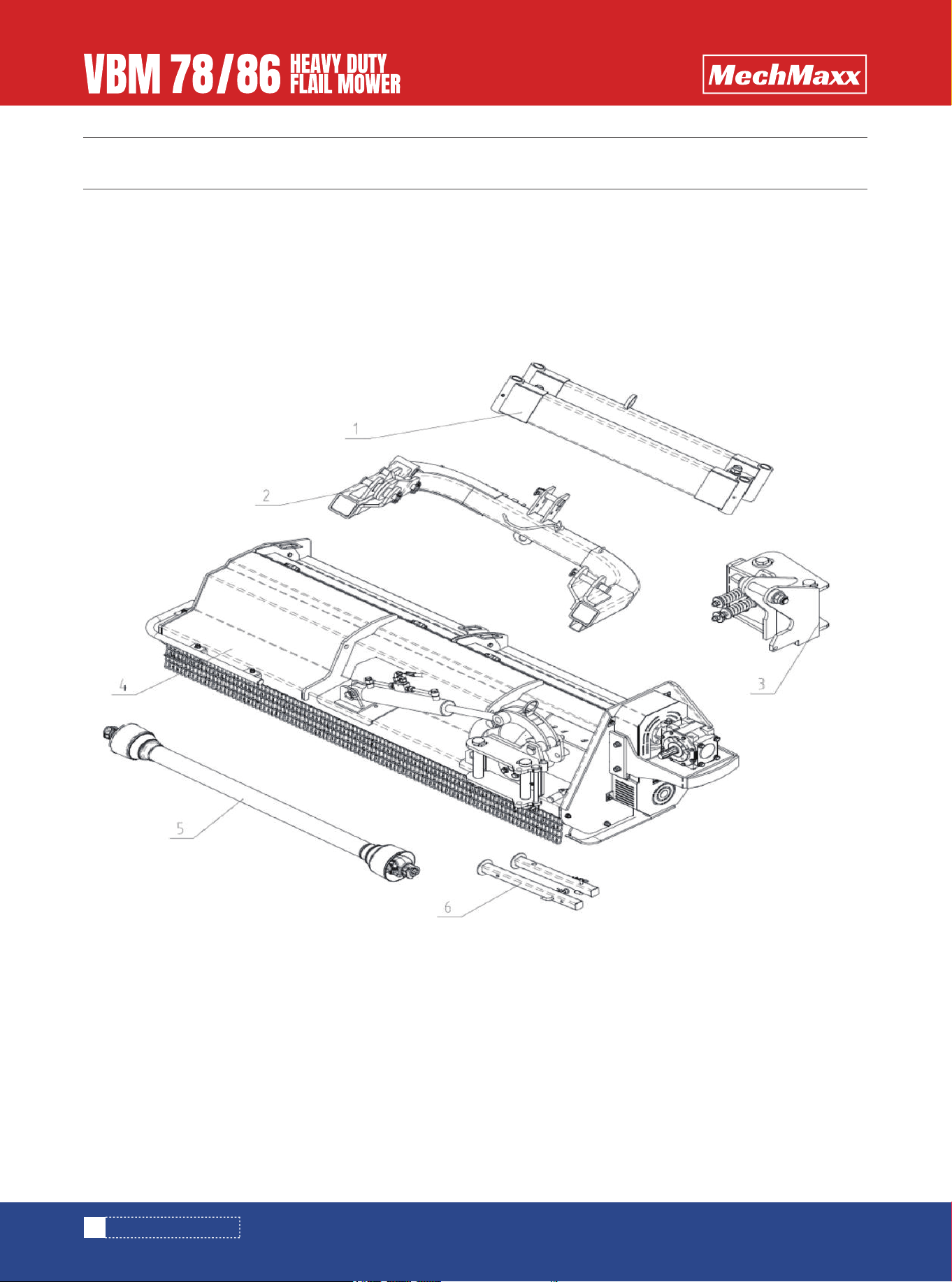
1. Remove and check
Remove the packing, check goods without defect and omission.
2. Packing List
The detailed packing list of the mower and accessory as the following table.
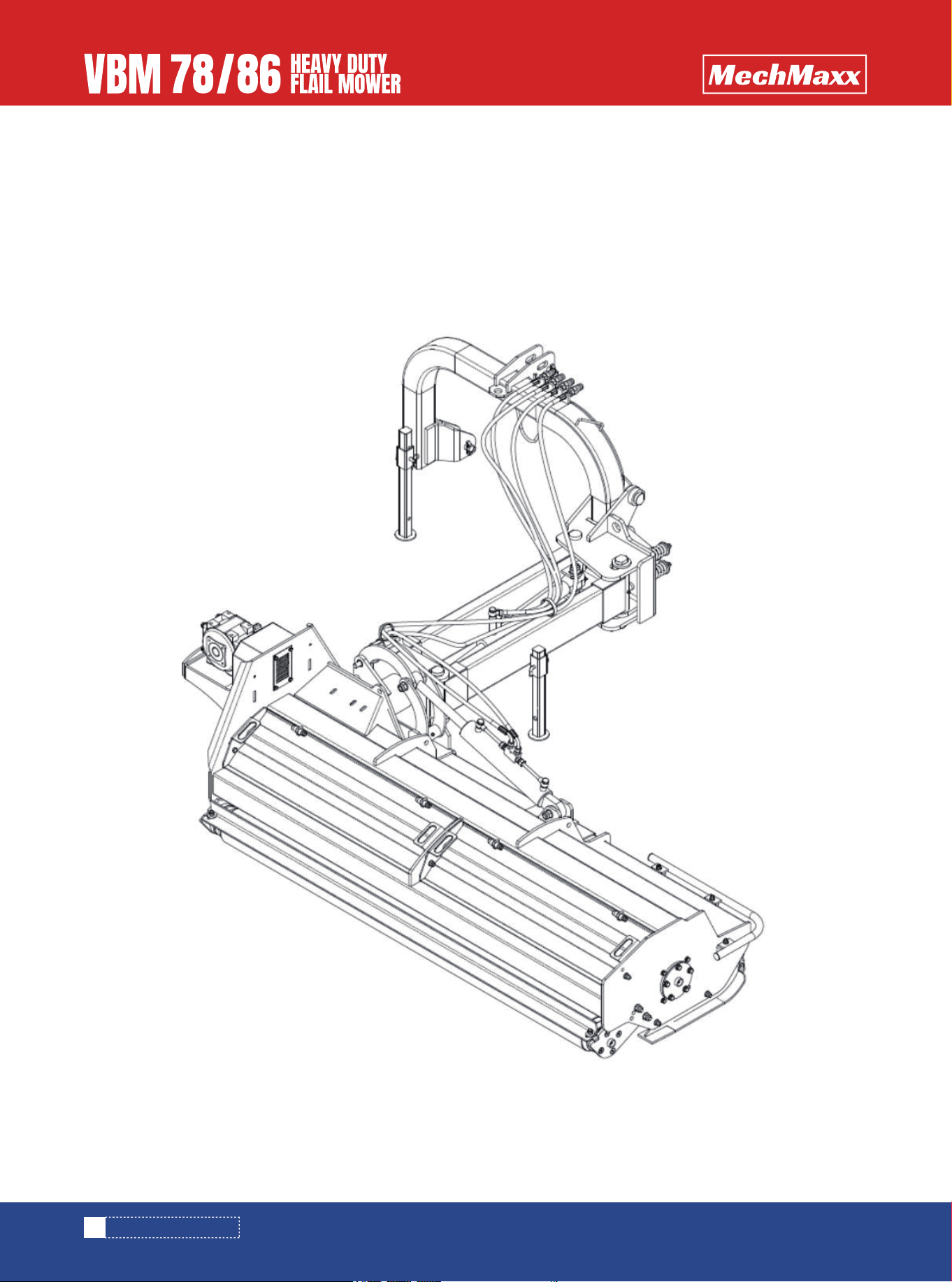
Figure 1-1: The Mower and Accessory in Package
7
www.mechmaxx.com
ASSEMBLY AND SET-UP
Item
1
2
3
4
5
6
1
1
1
1
1
2
Swing arms sub-assembly and fittings
Hitch tube weldment and fittings
Translation Plate Welding Component
Main body of the mower and fittings
PTO shaft
Support Leg assembly and fittings
Bubble film
Bubble film
Bubble film
None
None
Bubble film
Description Qty. Package Form
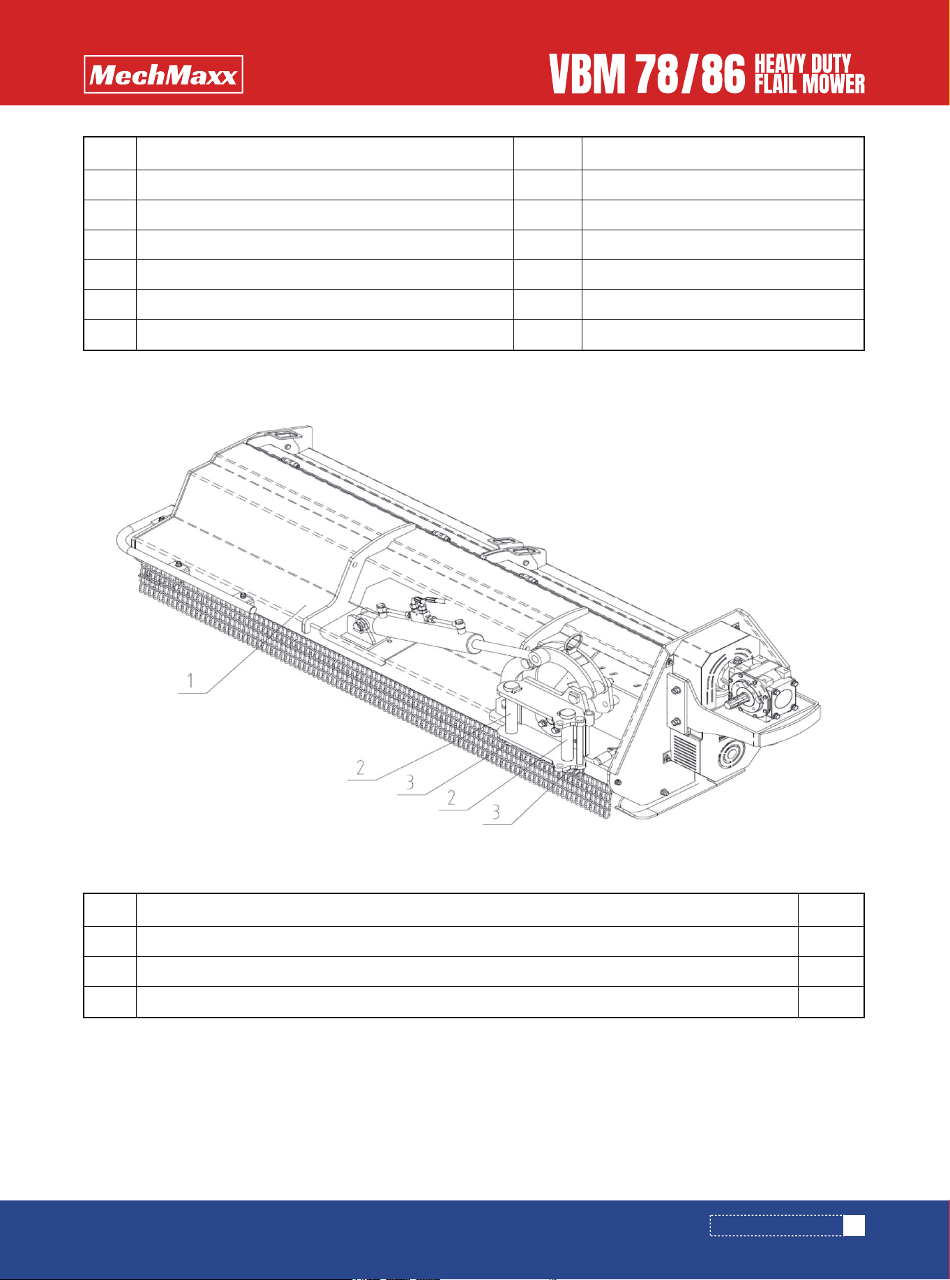
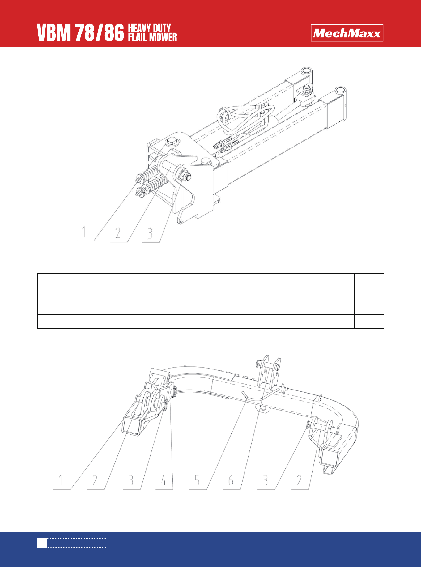
The detailed description of main body of the mower and fittings
The detailed description of swing arms sub-assembly and fittings
Figure 1-2: Main Body of The Mower and Fittings
Item
1
2
3
1
2
2
Main body of the mower
Swing arm pin-longer
Locknut M30x2
Description Qty.
8
www.mechmaxx.com
ASSEMBLY AND SET-UP
Figure 1-3: Swing Arms Sub-Assembly and Fittings
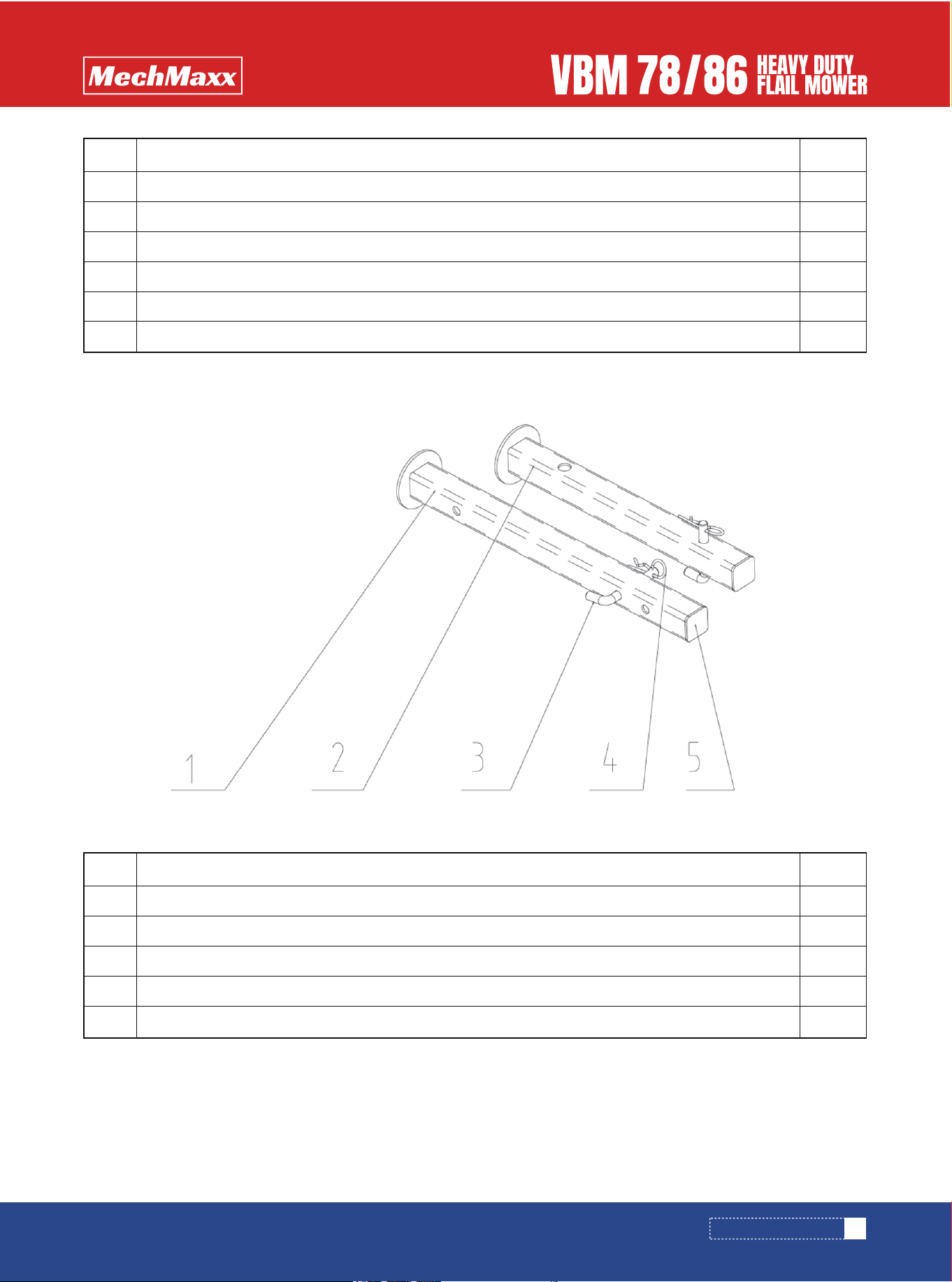
Figure 1-4: Hitch Tube Weldment and Fittings
The detailed description of hitch tube weldment and fittings
Item
1
2
3
1
1
1
Swing arms sub-assembly
Swing arm pin-Shorter
Locknut M30x2
Description Qty.
9
www.mechmaxx.com
ASSEMBLY AND SET-UP
Figure 1-5: Support Leg Assembly
The detailed description of Support Leg Assembly
Item
1
2
3
4
5
6
1
3
4
1
1
1
Hitch tube weldment
Hitch pin - Lower
Safety lock pin
Small hanging weldment
PTO shaft hook
Hitch pin - Upper
Description Qty.
Item
1
2
3
4
5
1
1
2
2
2
Long Support Leg Welded Parts
Short Support Leg Welded Parts
Support Leg Pin
R Pin 3.2
40 Leg Cover
Description Qty.
ASSEMBLY AND SET-UP
10
www.mechmaxx.com
INSTALLATION WIZARD
The installation wizard will guide you to finish the final assembly of your new mower easily.
1. Tool Required
Air impact wrench with 46mm sleeve
T type socket wrench 13mm
T type socket wrench 18mm
2. Torque Application
Refer to bolt torque in Section 7 Appendix.
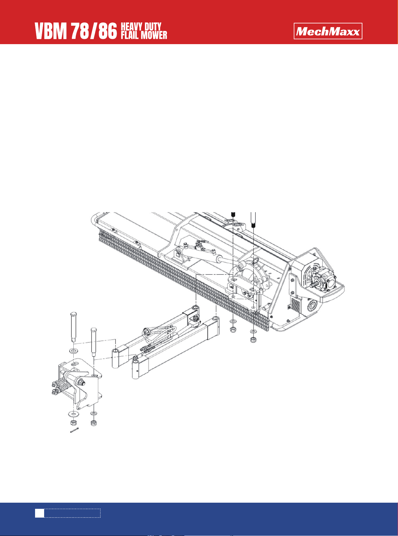
3. Assembly
Step1: Installing Swing Arms Sub-Assembly
Remove the packaging of swing arms sub-assembly and fittings.
Push swing arms sub-assembly into the overturning bracket weldment as shown in figure1-6. Fix it with 2pcs of swing
arm pins-longer, 2pcs of locknuts M30x2.
Tighten locknuts completely.
Figure 1-6: Installing Swing Arms Sub-Assembly
ASSEMBLY AND SET-UP
11
www.mechmaxx.com
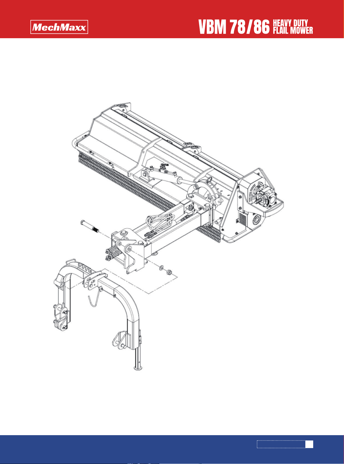
Step2: Installing Hitch Tube Weldment and Fittings
Remove the packaging of hitch tube weldment and fittings.
Fix hitch tube weldment to swing arms sub-assembly with 1pcs of swing arm pin-shorter, 1pcs of locknut M30x2.
Tighten locknuts completely.
Figure 1-7: Installing Hitch Tube Weldment and Fittings
12
www.mechmaxx.com
ASSEMBLY AND SET-UP
Step3: Installing Rake Sub-Assembly
Remove the packaging of Rake Sub-Assembly.
Insert raker weldment-longer into the tube on swing arm weldment-L as well as raker pin and insert R pin into the hole on
raker pin. Insert raker weldment-shorter into the tube on hitch tube weldment as well as raker pin and insert R pin into
the hole on raker pin. Pass all oil pipes through the guide ring and fix them with oil pipe clamps.
Note: The length of oil pipes between oil cylinders and pipe clamps shall be reserved with allowance to prevent oil pipes
from being damaged during swing arms moving left and right and main body of the mower turning up and down.
Figure 1-8: Installing Rake Sub-Assembly and Oil Pipes Fixation
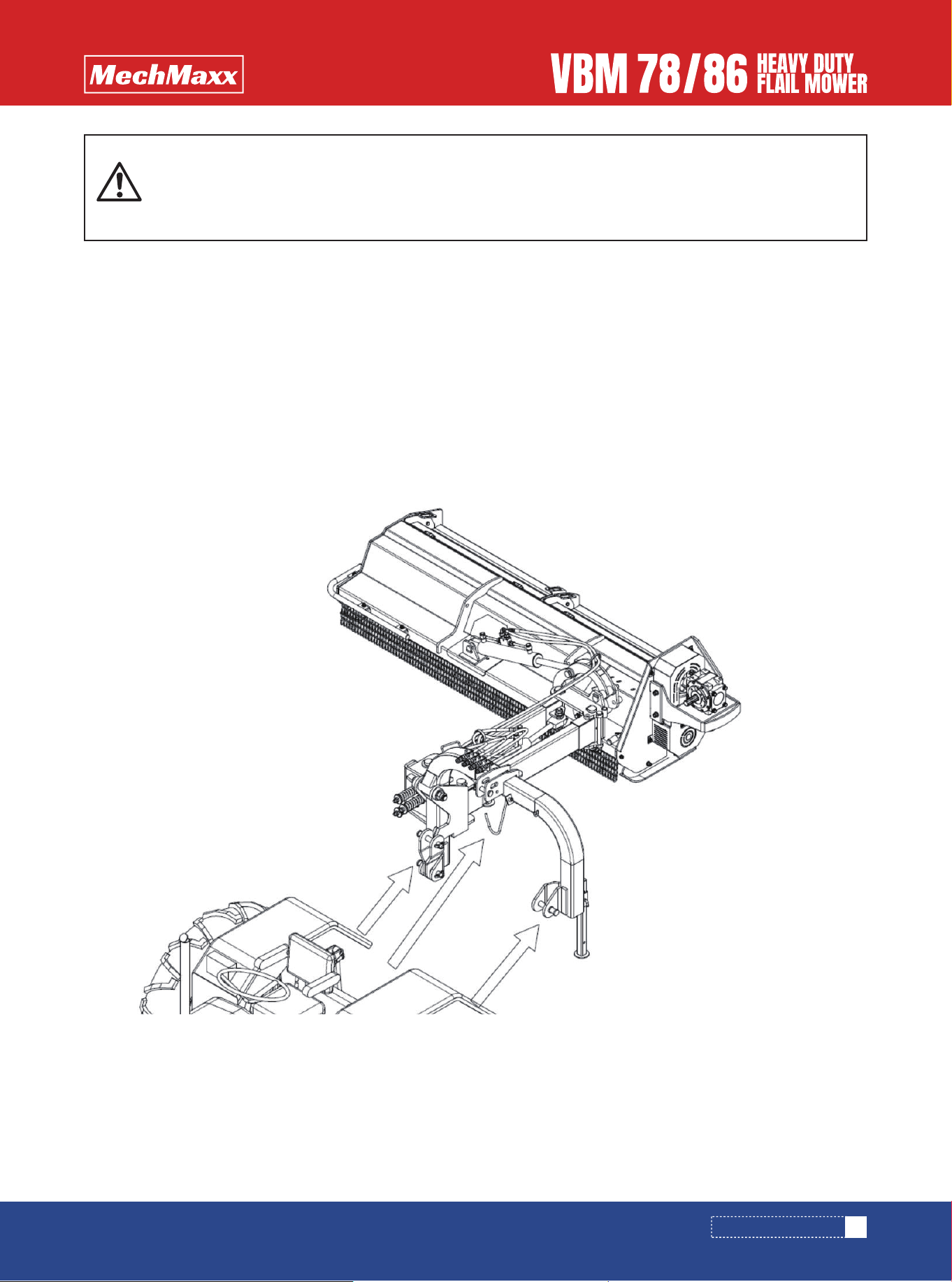
TRACTOR HOOK-UP
1. Be certain that tractor draw bar will not interfere. Move draw bar ahead or remove if required. Draw bar should also be
checked for clearance when unit is being raised for the first time.
2. Align lower link arms of tractor to hitch clevises on mower. Insert lower hitch pins into lower ball swivels and attach
link pins.
3. Attach tractor top link to upper floating hitch on mower with pin supplied. Secure with lock pin.
4. Adjust tractor top link in or out to place upper hitch pin vertically above or slightly behind lower hitch pins to allow
mower flotation.
The mower should be run with the back 15 degrees lower than the front.
Figure 1-9: Tractor Hook-up
13
www.mechmaxx.com
Fill the gearbox with proper amount of gear oil before operation.
Ensure that the height of the rotation axis from the ground is greater than 700mm,otherwise one
side of the mower will touch the ground in advance, resulting in damage to the connecting plate and
hinging bracket. Refer to figure 1-6.
WARNING
ASSEMBLY AND SET-UP

DRIVELINE INSTALLATION
1. Slide driveline end with extended safety cone over spline shaft of gearbox and secure with attaching device.
2. Slide driveline over tractor’s spline PTO shaft and secure with locking device of driveline.
3. Driveline should now be moved back and forth to ensure that it is secure on the PTO shaft of the tractor and mower
gearbox.
4. Attach chain from the driveline shield to one of the upper hitch braces to ensure that the shield does not rotate.
5. Should driveline require shortening:
a. Hold the half-shafts next to each other in the shortest working position and mark them.
b. Shorten inner and outer guard tubes equally.
c. Shorten inner and outer sliding profiles by the same length as the guard tubes.
d. Proper overlap is a minimum of one-half the length of each tube, with both tubes being of equal length.
e. Round off all sharp edges and remove burrs. Grease sliding profiles.
14
www.mechmaxx.com
Tractor PTO shield and all mower guards must be always in place during operation!
CAUTION
ASSEMBLY AND SET-UP

15
www.mechmaxx.com
OPERATING INSTRUCTIONS
OPERATING INSTRUCTIONS
MUST ADD OIL BEFORE FIRST USE.
TRANSPORTING
MOWING INSTRUCTIONS
THE GEARBOX AND TRANSMISSION ARE SHIPPED WITH-
OUT OIL.
ADD OIL BEFORE FIRST USE!
Gear Oil SAE90 700ml
NOTE: Always disengage PTO before raising mower to
transport position.
1. When raising the mower to transport position, be sure
that driveline does not contact tractor or mower. Adjust
and set the tractor’s 3- point hitch lift height so that the
driveline does not contact mower deck in the fully raised
position.
2. Be sure to reduce tractor ground speed when turning,
leaving enough clearance so that the mower does not
contact obstacles such as buildings, trees or fences.
3. Select a safe ground travel speed when transporting
from one area to another. When traveling on roadways,
transport in such a way that faster moving vehicles may
pass safely.
4. When traveling over rough or hilly terrain, shift tractor
to a lower gear.
1. Clear area to be mowed of objects and debris that
might be picked up and thrown by the mower blades.
2. Grass is best cut when it is dry. Mowing wet grass can
cause plugging resulting in grass clumps behind the
mower.
3. Grass should be mowed frequently as shorter clippings
deteriorate faster.
4. If mowing extremely tall grass, it is best to raise
cutting height and mow the area, then lower cutting
height and mow a second time at the desired height.
OPERATING INSTRUCTIONS
Proper servicing and adjustments are the key to the long
life of any machine. With careful and systematic inspec-
tion of the mower, costly maintenance, time and repair
can be avoided.
Before beginning to mow, the following inspection should
be performed:
1. Check oil level in gearbox.
2. Check that all plugs in gearbox have been replaced and
tightened properly.
3. Be sure all mower knives, bolts and nuts are tight.
4. Be certain all guards and shields are in place and
secure.
5. Grease driveline shaft and all other grease fittings.
6. Clear area to be mowed of rocks, branches and other
foreign objects.
7. Lower mower to ground. Set tractor throttle at approxi-
mately 1/4 open. Engage PTO to start blades rotating.
8. Operate with 540 rpm PTO tractor.
9. At first begin mowing at a slow forward speed and shift
up until the desired speed is achieved - maintaining 540
PTO rpm.
10. Mower knives will cut better at a faster blade speed
than at reduced throttle.
11. After mowing the first 50 feet, stop and check to see
that the mower is adjusted properly.
12. Do not make sharp turns or attempt to back up while
mower is on the ground.
13. Do not engage PTO with mower in the fully raised
position. Do not engage PTO at full throttle.
When traveling on public roads, whether
at night or during the day, use accessory
lights and devices for adequate warning to
operators of other vehicles. Comply with
all Federal, State, and local laws.
CAUTION

ADJUSTMENTS
LEVELING THE MOWER
NOTE: Tractor and mower should be on level ground.
Leveling can be adjusted at the tractor’s 3-point arms and
center link.
CUTTING HEIGHT ADJUSTMENT
The machines cutting height depends upon the position of
the rear roller.
1. Remove the bolts that fix the roller on both sides.
2. Lift or lower both sides of roller in equal measurements.
3. Replace bolts and re-tighten.
3-POINT HITCH ADJUSTMENTS
BELT TENSION
The 3-point hitch system on this mower has been
designed for front to back flotation when mowing on
uneven terrain. Adjust tractor’s top center link to place
the upper hitch pin vertically above or slightly behind the
lower hitch pins. The mower should be run with the back
15 degrees lower than the front.
The hitch can also be adjusted from side to side by turning
the adjustment handle. Turn handle until you have
achieved your desired location.
The Belt tension should be checked after the first 20
hours of use. And then every 40 hours of use.
1. Tension on the belt can be adjusted with the belt
tension bolt. Turn the bolt until desired tension is
achieved. When the belt has the correct tension the
gearbox should be adjusted so that the gearbox extension
is running straight (parallel) with the flail mower. Loosen
bolts at the bottom of the gearbox and move gearbox until
gearbox extension is running straight.
2. Excessive tension on the belt may lead to premature
failure of belt and drive components.
16
www.mechmaxx.com
Engage parking brake, shut off tractor,
remove key and disengage PTO before
making any height adjustments!
CAUTION
Belt drive system under spring tension;
use care to avoid bodily harm!
CAUTION
Excessive tension on the belt may lead to
premature failure of belt and drive compo-
nents. Excessive tension on the belt may
also lead to a safety hazard to the opera-
tor or bystanders.
CAUTION
ADJUSTMENTS
MAINTENANCE AND LUBRICATION
MAINTENANCE STORAGE
Proper servicing and adjustment is the key to the long life
of any farm implement. With careful and systematic
inspection, you can avoid costly maintenance, time and
repair.
At the end of the working season or when the mower will
not be used for a long period, it is good practice to clean
off any dirt or grease that may have accumulated on the
mower and any of moving parts.
1. Clean as necessary.
2. Check knives for wear and replace if necessary.
3. Inspect mower for loose, damaged or worn parts and
adjust or replace as needed.
4. Store unit inside if possible for longer life.
5. Repaint parts where paint is worn or scratched to
prevent rust.
6. Replace all damaged or missing decals.
Driveline Shaft U-Joints
Type of Lubrication: Multi-purpose Grease
Roller Bearing (Both Ends)
Type of Lubrication: Multi-purpose Grease
KNIFE REPLACEMENT
LUBRICATION
V-BELT INSTALLATION
IMPORTANT Make sure that the knife is the same length
as the others on the mower. This will keep the rotor
rotation balanced.
1. Remove bolt and nut.
2. Remove old knife.
3. Install new knife and existing bolt.
4. Secure with nut.
17
www.mechmaxx.com
For safety reasons, each maintenance
operation must be performed with tractor
PTO disengaged, mower lowered com-
pletely to ground and tractor engine shut
off with ignition key removed.
1. After using the mower for several
hours, check all bolts to be sure they are
tight and check drive belt tension.
2. Replace any worn, damaged or illegible
safety decals by obtaining new decals
from dealer.
CAUTION
Belt drive system under spring tension;
use care to avoid bodily harm!
1. Remove belt guard fender and belt
cover.
2. Disengage belt tension by loosening
belt tension bolt until belt can be
removed.
3. With tension relieved from belt remove
old belt from pulleys.
4. Tighten belt tension bolt.
5. Reinstall belt guard and belt guard
fender.
CAUTION
MAINTENANCE AND LUBRICATION

Cutter Rotor Bearing (Both Ends)
Type of Lubrication: Multi-purpose Grease
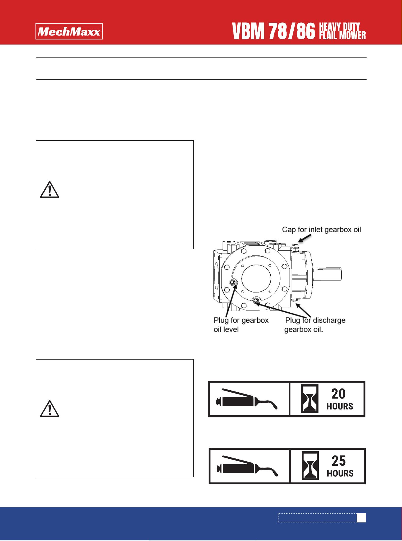
Check Gearbox oil
Type of Lubrication: SAE 90W Gear Lube
Check oil level in gearbox by removing the plug located on
the right-hand side. Oil should be level with bottom of plug
hole. Add oil if necessary, by removing top fill plug and side
plug. Add oil until it flows from side plug hole.
Do not overfill!
IMPORTANT: Mower should be level when checking oil in
gearbox!
18
www.mechmaxx.com
MAINTENANCE AND LUBRICATION

SPECIFICATIONS & CAPACITIES
19
www.mechmaxx.com
Power Required
Working Width
Overall Width
Blade Ground Clearance
Max. Cutting Diameter
Offset Distance from The Center (Maximum)
Tilt-Up Angle
Tilt-Down Angle
Number Of Blades
Number of Belts
Blade Type
Blade Weight
Blade Material
Belt Adjustment
Working Efficiency
Rotor Diameter
Rotor Thickness
Rear Roller Diameter
Rear Roller Thickness
PTO Shaft Speed
Deck Thickness
Side Plate Thickness
Driveline Shaft Length
Spline End
3-Point Hitch
Gearbox Oil Type
Finish
Warranty
Shipping Box
Weight (N.W./G.W.)
80-110 Hp
78 in
94 in
0.5 in-2.6 in
6 in
122 in
90°
55°
18
4
Hammer
2.6 lbs
Cast Steel
Bolt Tightening
450 cu.ft./Hr.
5.5 in
0.5 in
6 in
0.25 in
540 rpm
2 in
0.25 in
T6-LF-73 With Shear Bolt; 73in-126in
1.375in Z6
CAT 2
85W-90
Powder Coating
1 Year
100x41x31 in
1848/2040 lbs
90-120 Hp
86 in
101 in
130 in
90°
55°
20
109 X 41 X 31in
1848/2040 lbs
Model VBM78 VBM86
SPECIFICATIONS & CAPACITIES

TROUBLESHOOTING
20
www.mechmaxx.com
Unplug and clean mower deck.
Remove belt guard shields and clean sheaves.
Replace belt.
Mow at full throttle (540 PTO rpm), check PTO speed and tractor engine.
Shift transmission to a lower gear.
Tighten belts.
Replace missing knives.
Replace knives.
Replace drive belt.
Replace pulleys or align.
Remove belt guard shields & clean debris from belt area & sheaves.
Raise cutting height by adjusting roller.
Change mowing pattern.
Reduce speed turns.
Shift to a lower gear.
Level mower.
Replace missing knives.
Mow at full throttle (540 PTO rpm).
Shift to a lower gear.
Clean mower.
Do not try to clean rear discharge area when mower is running. Bodily harm may occur!
Belt slipping
Patches of uncut
grass
Excessive vibration
Gearbox noisy
Knives scalping
grass
Uneven cut
Tractor loaded
down by mower
Check lubricant level.
Problem Solution
TROUBLESHOOTING

APPENDIX
WARRANTY
BOLT TORQUE
MECHMAXX warrants to the original purchaser that this
product will be free from defects in material and work-
manship beginning on the date of purchase by the end
user according to the following schedule when used as
intended and under normal service and conditions for
personal use.
Overall Unit and Driveline: One-year.
Blades and Belts: Considered wear items.
This warranty is limited to the replacement of any defec-
tive part by manufacturer and the installation by the
dealer of any such replacement part, and does not cover
common wear items such as blades, belts, tines, etc.
MECHMAXX reserves the right to inspect any equipment
or parts which are claimed to have been defective in
material or workmanship.
This warranty does not apply to any part or product which
in MECHMAXX’s judgment shall have been misused or
damaged by accident or lack of normal maintenance or
care, or which has been repaired or altered in a way which
adversely affects its performance or reliability, or which
has been used for a purpose for which the product not
designed. Misuse also specifically includes failure to
properly maintain oil levels, grease points, and driveline
shafts.
Claims under this warranty must be made to the dealer
which originally sold the product and all warranty adjust-
ments must be made through such dealer. MECHMAXX
reserves the right to make changes in materials or design
of the product at any time without notice.
This warranty shall not be interpreted to render MECH-
MAXX liable for damages of any kind, direct, consequen-
tial, or contingent to property. Furthermore, MECHMAXX
shall not be liable for damages resulting from any cause
beyond its reasonable control. This warranty does not
extend to loss of crops, any expense or loss for labor,
supplies, rental machinery or for any other reason.
The tables shown below give correct torque values for
various bolts and cap screws. Tighten all bolts to the
torques specified unless otherwise noted. Check tight-
ness of bolts periodically, using bolt torque chart as a
guide. Replace hardware with the same strength bolt.
Bolt
Diameter
SAE 2
N.m lb-ft N.m lb-ft N.m lb-ft
SAE 5 SAE 8
Bolt Torque
1/4"
5/16"
3/8"
7/16"
1/2"
9/16"
5/8"
3/4"
7/8"
8
13
27
41
61
95
128
225
230
6
10
20
30
45
60
95
165
170
12
25
45
72
110
155
215
390
570
9
19
33
53
80
115
160
290
420
17
36
63
100
155
200
305
540
880
12
27
45
75
115
165
220
400
650
ENGLISH TORQUE SPECIFICATIONS
Bolt
Diameter
8.8
N.m lb-ft N.m lb-ft
10.9
Bolt Torque
M3
M4
M5
M6
M8
M10
M12
M14
M16
M20
M24
M30
M36
0.5
3
6
10
25
50
90
140
225
435
750
1495
2600
0.4
2.2
4
7
18
37
66
103
166
321
553
1103
1917
1.8
4.5
9
15
35
70
125
200
310
610
1050
2100
3675
1.3
3.3
7
11
26
52
92
148
229
450
744
1550
2710
METRIC TORQUE SPECIFICATIONS
21
www.mechmaxx.com
APPENDIX
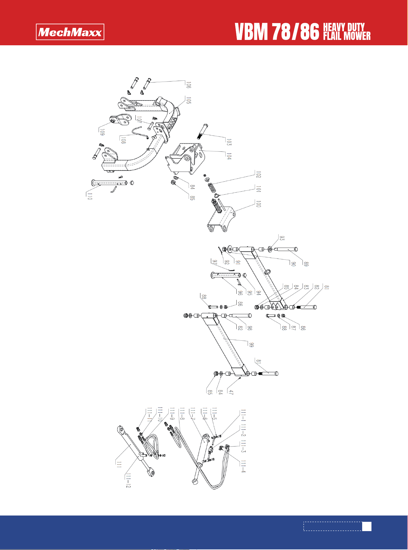
PART BREAKDOWN LIST
22
www.mechmaxx.com
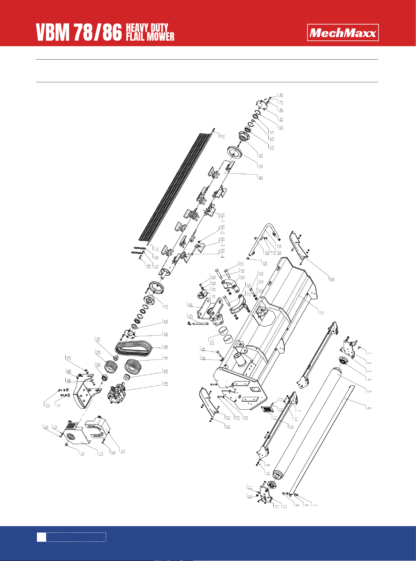
PART BREAKDOWN LIST
23
www.mechmaxx.com
PART BREAKDOWN LIST

PARTS LIST
9
1
4
2
1
1
13
4
9
1
3
7
4
4
2
21
4
8
1
1
1
2
6
1
1
3
13
3
2
1
No. No.DESCRIPTION QTY
1
2
3
4
5
6
7
8
9
10
11
12
13
14
15
16
17
18
19
20
21
22
23
24
25
26
27
28
29
30
Bolt M12*30
Roller Mounting Plate -Right
Bolt M16 * 50
Reverse Installation Of Bearing Ucu207
Roller Welded Parts
Clean Shoe
Nut M12
Large Washer 12
Bolt M12 * 40
Roller Mounting Plate-Left
Straight Through Pressure Oil Cup M8 *1
Nut M16
Flat Washer 16
Internal Hexagonal Bolt M12 *60
Rear Cover Welding Parts
Flat Washer 12
Bolt M8 * 16
Washer 8
Sealing Plate 01
Base Weldment 02
Hood Welding Parts
Nut M14
Bolt M14 *45
Base Weldment 01
Collision Bar Welded Parts
Nut M10
Flat Washer 10
Bolt M10*30
24 Cover
Pin Shaft 06
4
4
1
1
1
1
1
4
4
8
1
1
1
1
6
10
8
14
1
4
2
1
2
2
2
1
1
18/20
18/20
18/20
DESCRIPTION QTY
31
32
33
34
35
36
37
38
39
40
41
42
43
44
45
46
47
48
49
50
51
52
53
54
55
56
56-1
56-2
56-3
56-4
Washer 20
Nut M20
Pin Shaft 04
Pin Shaft 05
Lower Moon Plate Weldment
Upper Moon Plate Weldment
Pin Shaft 03
Bolt M14*35
Elastic Washer 14
Flat Washer 14
End Cap
Yoke Shaft Welding Component
Positioning Pin 01
Positioning Pin 02
Lock Pin Welded Parts
Bolt M12 * 45
Grease M10
Washers 12
Blind Cover Weldment
Elastic Retaining Ring 80
Oil Seal 55x80x8
Retaining Ring 40
Bearing 1308
External Bearing Seat
Blade Axle Protective Sleeve
Blade Axle Assembly
Blade Axle Weldment
Nut M16* 1.5-10
Hammer (1200g)
Bolt M16*1.5*100-10.9
24
www.mechmaxx.com
PARTS LIST
No.

8
1
1
4
1
1
1
1
1
1
4
1
8
4
4
1
1
1
4
4
1
109
110
4
2
8
1
4
4
2
2
No. DESCRIPTION QTY
57
58
59
60
61
62
63
64
65
66
67
68
69
70
71
72
73
74
75
76
77
78
79
80
81
82
83
84
85
86
87
Bolt M10*45
Oil Seal 50x90x8
Transparent Cover 02
Toothed V-Belt Av17x1321
Large Pulley
Expansion Sleeve Reach 04 Type 33x80
Gearbox T102
Oil Seal Sleeve
Small Pulley
Sleeve Reach 04 40x80
Nut M14
Gearbox Seat
Large Washer 14
Bolt M16*35
Washer 16
Up Belt Cover
Lower Belt Cover
25 Cover
Enlarged Flat Cushion 8
Bolt M8* 20
Hanging Rod
Chain
Chain Spacer Sleeve
Nut M10
Long Selling
Bushing 44 *40 *50
Rear Swing Arm Weldment
Flat Washer 30
Nut M30 * 2
Nut M24
Flat Pad 24
2
1
1
1
1
1
2
2
1
2
1
1
1
6
3
1
1
1
3
1
1
1
1
1
4
1
1
1
8
2
1
No. DESCRIPTION QTY
88
89
90
91
92
93
94
95
96
97
98
99
100
101
102
103
104
105
106
107
108
109
110
111
111-1
111-2
111-3
111-4
111-5
111-6
111-7
Bolt M24*110
Pin Shaft 01
Washers 30
Nut M30*2
Split Pin 8 * 80
Pin Shaft 01 Gasket
40 Leg Cover
Support Leg Pin
Short Support Leg Welded Parts
R Pin 3.2
Pin Shaft 02
Front Swing Arm Welded Parts
Translation Plate Welding Component
Spring Washer
Avoid Compression Springs
Short Selling
Horizontal Bracket Welding Component
Suspension Bracket Welded Parts
Lower Suspension Pin
Upper Suspension Pin
A Hook
Small Hanging Bracket Welded Parts
Welding Parts For Long Support Legs
Hydraulic System Assembly
Hinged Bolt M16*1.5*45
Bidirectional Hydraulic Lock Vrpc-G3/8-121
End Straight Joint G3/8-M18*1.5
End Straight Joint G3/8-M18*1.5 (With Orifice)
Combination Washer 16
Ball Joint Assembly
Flip Cylinder 250
25
www.mechmaxx.com
PARTS LIST

2
2
4
4
1
2
No. DESCRIPTION QTY
111-8
111-9
111-10
111-11
111-12
112
Flip Cylinder Hydraulic Hose M18*1.5 Length:3750mm
Swing Cylinder Hydraulic Hose M18*1.5 Length:3000mm
End Straight Joint Npt1/2-M18*1.5
Quick Change Male Connector Npt1/2
Swing Cylinder
Bushing Sf-2-115 *110*60
26
www.mechmaxx.com
PARTS LIST