Operator’s Manual
www. mechmaxx.com
WARRANTY


TABLE OF CONTENTS
TABLE OF CONTENTS
SPECIFICATIONS
SAFETY SIGNS
INTRODUCTION
1
2
ENGINE
EXCESS CROP BUILD UP
11
11
VISUAL CHECK
11
TYRE PRESSURES
11
ROTOR BEARING INSPECTION
11
WHEEL BEARING INSPECTION
11
OIL 1.96 IN COUPLING/BUSH WEAR
11
GENERAL INSPECTION
11
ROTOR FLAIL MAINTENANCE
11
INTRODUCTION
TOWED EQUIPMENT
WEIGHT RATIOS
4
4
4
BRAKING
4
HITCHING AND LOADS
4
IN THE INTEREST OF SAFETY:DO NOT
IN THE INTEREST OF SAFETY:DO
INSTRUCTION&WARNING DECALS
6
6
6
INITIAL CHECK
DRAWBAR ADJUSTMENT
TO ADJUST
7
7
7
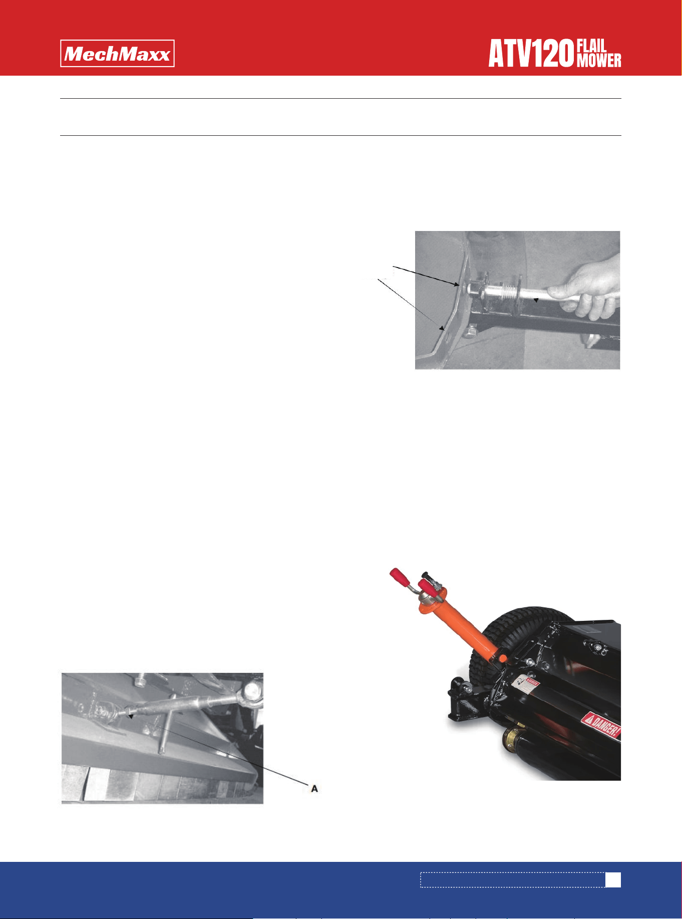
QUICK OFFSET DRAWBAR
MOWER CUTTING HEIGHT
CUTTING HEIGHT ADJUSTMENT:
7
7
7
STARTING THE ENGINE
8
FORWARD SPEED
STOPPING THE MOWER
STOPPING THE MOWER
8
8
8
ANTI-SCALPING ROLLER/SIDE SKIDS
9
TYRES AND WHEELS
4
MAXIMUM TOWED WEIGHT
4
MOUNTED EQUIPMENT
5
INSTRUCTIONS FOR MOUNTED AND
TRAILED EQUIPMENT
5
USING AN ATV
5
TRAINING
5
HELMETS
5
3
4
6
SAFETY
7
OPERATING INSTRUCTIONS AND ADJUSTMENTS
10
MAINTENANCE
13
PARTS DIAGRAM
14
PARTS LIST
1
www. mechmaxx.com
TABLE OF CONTENTS

SPECIFICATIONS
2
www. mechmaxx.com
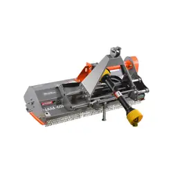
SPECIFICATIONS
Engine
Working Width
Overall Width
Cutting Height
Number of Blades
Blade Type
Size of Blades
Blade Weight
Blade Material
Rotor Bearing
Rotor Rotation
Drive Type
Number of Belts
Belt Size
Tire Size
Finsh
Warranty
Net Weight/Gross Weight
DUCAR DH420E 420cc/15hp Electric Start Gasoline Engine
48 in
72 in
0.4-2.5 in
20
Hammers
4x2.6 in
0.8 lbs
Cast Steel
SKF Bearing
Reverse
Belt Drive
3
0.7x40 in (17X1016)
16 in
Powder Coat Paint Galvanized Steel
1 Year
609lbs/675lbs
Model ATV120
3
www. mechmaxx.com
SAFETY SIGNS
The rating plate on your machine may show symbols. These represent important information about the product or instruc-
tions on its use.
SAFETY SIGNS
Do not open or remove safety shields while
engine is running.
PINCH POINT
HAZARD
Keep clear
GUARD MISSING
WHEN THIS IS VISIBLE
DO NOT OPERATE
ENTANGLEMENT HAZARD
BELT DRIVE:
HAND AND ARM
ENTANGLEMENT
HAZARD.
FLYING OBJECTS
HAZARD
Keep clear.
The PTO Driveline MUST be
measured and cut (if required) as
per the Owner's Manual.
Failure to do so will result in
damage to both the tractor
and the implement.
Read and understand
operators manual
before using this
machine.
ROTATING
BLADES
KEEP HANDS
AWAY
DO NOT go under frame when rotor is turning or engine
is running. Keep others away.
ROTATING KNIVES HAZARD
Disconnect & lockout power source BEFORE adjusting
or servicing.
Keep hands, feet, hair, and clothing away from moving
parts.
To prevent serious injury or death from rotating knives:
Relieve pressure before disconnecting lines.
Do Not use hands to check for leaks.
Consult physician immediatly if skin
penetration occurs.
HIGH PRESSURE FLUID
HAZARD

4
www. mechmaxx.com
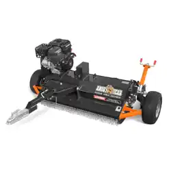
INTRODUCTION
INTRODUCTION
With the purchase of your FLAIL MOWER you have made
an excellent choice.
This machine should give first class service for a long
time, if used correctly, and maintained as described in
this manual.
Fitted with an easy to start engine it has been designed
to cope with a wide range of conditions. The AT – Flail
mower incorporates easy height adjustment, range of
engine options and a full width anti-scalping roller to
avoid damage to machine and sward.
The mower is constructed from 4mm steel for added
strength; all fittings are of high quality to ensure years of
trouble free use.
Different wheel options are available for the AT Flail
Mower
Engines used may wary, but all are accompanied by the
maker’s usual warranty.
1.Brakes to trailed equipment.This helps prevent
jack-knifing when braking or traveling downhill;
2.Over-run brakes which come into action whenever
theATV brakes are applied;
3.A manually operated parking brake operable from the
driving position.This provides control for use when going
up slopes.
Stability is also improved if:
1.Some weight is transferred from the trailer onto
theATV draw-bar;
2.The draw-bar has a swivel hitch and the ATV a ball
hitch having a large head to neck ratio.This makes it
easier for the draw-bar hitch to swivel and cope with
undulating ground;
3.The load is positioned as near to the centre of the
trailer as possible.
1.Check tyre pressures regularly with a pressure gauge
capable of reading low pressures accurately;
2.Check tyres regularly for damage and wear;
3.Select equipment which has tyres and wheels that can
cop with speeds over 20mph and occasional higher
speeds;
4.Use wheels with bead locks on the rims if the main
use is going to be on sloping ground.This prevents tyre
run-off on side slopes.
Follow the advice given by manufacturers on the maxi-
mum trailed weight.This will be found on the equipment
or in the instruction handbook.
Note:Universal road going trailers will normally have the
maximum gross weight stated on a separate notice.
This information sheet gives advice to users on how to
use all Terrain vehicles(ATVs)safely with towed and
mounted equipment.
Plan the use of an ATV carefully and take particular note of
ground conditions and slopes,as these may vary consider-
ably,depending on the terrain,weather conditions,ground
surface and the crop under the wheels.
1.The safe ratio between the trailed laden maximum
weight and unladen weight of the ATV must be assessed
for each operation.
2.Always take note of information given in the manufac-
ture’s handbook when making this assessment.
3.As a guide research shows that on level ground,4 x
unladen weight of the ATV for braked trailed equipment
and 2 x unladen weight of the ATV for unbraked trailed
equipment are the appropriate maximum retios.
Choose equipment which matches your ATV.Stability of
towed equipment is affected by:
Note:For work on slopes or uneven ground the ratio will
need to be reduced.
Fit:
INTRODUCTION
BRAKING
HITCHING AND LOADS
TYRES AND WHEELS
MAXIMUM TOWED WEIGHT
TOWED EQUIPMENT
WEIGHT RATIOS

5
www. mechmaxx.com
INTRODUCTION
ATVs using mounted equipment are safer if the equipment
has:
• a low centre of gravity.This improves stability.
• a gross weight within the limits approved by ATV manu-
facturer.
• no dangerous projections to injure the operator or
bystanders;
• no forward projections which stop head protection
beingworn;
• controls which are easy to work and which do not creat
a hazard to the operator
Take note of the manufacturer’s instructions on:
• operating on slopes;
• where to place loads so as to give fore/aft and lateral
stability;
• the risks of using equipment with negative drawbar
nose weight,ie loss of traction;
• the maximum operating speed;
• the effect that equipment carried on front and/or rear
racks will hace on longitudinal and lateral stability;
• securing loads;
• the use of ballast,if any,to improve stability;
• the need to select and use safe routes.
• read the manufacturer’s instruction book and take note
of the safety advice given;
• Choose an ATV with enough power for the work you want
it to do
• four-wheel driver will give better traction and mobility
and may provide a margin of safety;
• Choose a safe route;
• Be aware that increased speed greatly increases the
risk of instability and the risk of an overturn;
Train everyone who has to use an ATV whether with
mounted or trailed equipment or as a solo machine.The
training should emphasise the factoes affecting stabili-
ty,the need for care and concentration,and how to recog-
nise the conditions which may affect the safety of opera-
tion,It is important for trainees to familiarize themselves
with the handing and control of the machine on level open
ground before tackling rough hill terrain.
Suitable training courses are run by bodies such as ATB
Landbase and the forestry Authority.
MOUNTED EQUIPMENT
INSTRUCTIONS FOR MOUNTED AND
TRAILED EQUIPMENT
USING AN ATV
TRAINING
Wear head protection which protects the head and
neck.Helmets are suitable.Some users find open faced
helmets more suitable than full face helmets.
HELMETS

6
www. mechmaxx.com
SAFETY
IN THE INTEREST OF SAFETY:DO NOT
INSTRUCTION&WARNING DECALS
IN THE INTEREST OF SAFETY:DO
SAFETY
1. DO NOT–Operate the mower without all the correct
guards fitted.
2. DO NOT–Alter engine settings unless stated by Engine
manufacturer.
3. DO NOT–Touch any moving or rotating parts,during
working conditions
4. DO NOT–Stop the engine immediately after heavy use,(-
See section 5.6)
5. DO NOT–Operate the mower without suitable ear and
eye protection
6. DO NOT–Allow passengers.
7. DO NOT–Leave machine un-attended while operating
8. DO NOT–Run the engine in an enclosed area,exhaust
gases containCarbon Monoxide and are fatal if in haled.
9. DO NOT–Operate the mower on excessively steep
slopes.
10. DO NOT–Operate the mower unless all safety features
are fitted to the mower and are used correctly.
11. DO NOT–Operate the mower until you have read and
understood the entire operators manual
12. DO NOT–Wear loose fitting clothing,to avoid catching
on parts of the machine
13. DO NOT–Try to remove blockages while the engine is
running.Ensure engine is stopped and the rotor has
finished rotating,before any servicing takes place to your
mower.
14. DO NOT–Operate the mower in Dark conditions unless
suitable artificial light is used.
15. DO NOT–Operate if excessive vibration occurs,stop
the machine immediately and view maintenance chart.
16. DO NOT–Climb on the mower.
5. DO–Reduce speeds when working on hillsides or rough
terrain
6. DO–Be aware components can be hot after operation
7. DO–Follow any towing guidelines stated by ATV manu-
facturer.
8. DO–Show some caution when filling the tank with
petrol,especially if engine components are hot.
9. DO–Ensure all safety decals are in good condition,re-
place any that are damaged.
10. DO–Keep hands and feet away from rotating blades
11. DO–Ensure mower is in transport position before
transporting from workplace.
KEEP WHEEL NUTS TIGHT CHECK DAILY
REFER TO THE OPERATORS MANUAL FOR CORRECT TYRE
INFLATION
PRESSURE OBSERVE TOWING VEHICLE MAX TOWING
LIMITS OR TRAILER MAX WEIGHTS
1. DO–Follow Engine manufactures guideline.
2. DO–Ensure all spectators are a safe distance away
when operating.
3. DO–Carry out regular servicing and checks before use.
4. DO–Clear cutting area from potential damaging compo-
nents.
Your responsibilities before operating
this machine are:
• Read Understand and Follow the safety
procedures manual
• Train operators before using&review
safety procedures regularly
• Ensure that all guards are in place before
operating
• Keep Hand,Feet,Hair and Clothing away
from all moving parts
• Avoid wearing loose clothing whenever
possible
• Maintain as per schedule in the safety
procedures.Especially Blades and Secur-
ing Hardware,due to the hazard they pres-
ent should any part break loose during
operation
• During maintenance,use suitable
support stands
• DO NOT allow any persons to ride on the
equipment
7
www. mechmaxx.com
INITIAL CHECK
QUICK OFFSET DRAWBAR
MOWER CUTTING HEIGHT
CUTTING HEIGHT ADJUSTMENT:
DRAWBAR ADJUSTMENT
TO ADJUST
OPERATING INSTRUCTIONS AND ADJUSTMENTS
OPERATING INSTRUCTIONS AND ADJUSTMENTS
The ATV FLAILMOWER isdesignedtogivesafeanddepend-
ableserviceifoperated according to instructions and
intended use.
Read and understand this manual before operating the
mower,as failure to do so could result in personal injury or
equipment damage.
When used with anA.T.V or compact tractor,ear defenders
should be worn.Under normal working conditions a noise
level of 83 decibels would be usual,in this case protection
is advised.
Pull back the locking pin; slide the drawbar to the desired
position, and release the locking pin into the securing
hole, as shown.
The main cutting height adjustment is achieved by using
the screw jack, to raise or lower the cutting deck as
necessary.
Turn the handle to raise or lower as necessary.
1.Makesure tha tall nuts,bolts and fitting sare securely-
fixed,and that all packaging materials e.g.wire bands,tape
etc have been removed.(Remove tape from the front
stone deflectors from the underside of the body.
2.Check the there is oil in the engine and petrol in the
tank.
3.Check tyre pressures.
The draw barattach ment height of the towing vehicle can
vary. To accom modate adjustment,a screw link is located
beneath the drawbar. This should be lengthened or short-
ened so that the cutting deck is horizontal to level
ground. (This ensures a better cutting efficiency)
1. Unlock the locking nut (A)
2. Lengthen the link to lower the front of the deck or
shorten to raise the deck.
3. Once the deck is level, re-tighten locking nut (A).
Hole
settings

8
www. mechmaxx.com
OPERATING INSTRUCTIONS AND ADJUSTMENTS
Observe all safety precautions;keep hands and feet away
from rotor and other moving parts.Keep spectators at a
safe distance.
1.Make sure there is a gap between the blades and the
ground/crop
2.Select an area clear of loose debris that could be picked
up.
3.Set the engine choke,and suitable idling speed with the
throttle.
4.Place one foot on top of the deck body to give a firm and
balanced position.Pull the startercordfirmly,allowingthe-
cordtoreturntoreturntothehousingslowly(one or two
strong pulls should start the engine).
5.After a few seconds warming up at idling speed,move
the throttle to the factory pre-set working position to give
a normal/working engine R.P.M of 3600 max.
FAILURE TO DO THIS WILL RESULT IN CLUTCH SLIP AND
ULTIMATELY SEVERE DAMAGE TO THE CLUTCH AND DRIVE
BELTS.
NORMAL FORWARD SPEED(1 kph–very heavy use–10
kph–very light use)Start off in the slowest speed possi-
ble,ensure the mower is working efficiently with the
engine set at maximum RPM and not labouring.(If this is
not possible due to very heavy cutting conditions,raise
cutting height of blades and be prepared to go over twice
with machine set lower on 2nd pass,leave at least 24
hours in between 1st and 2nd cut to allow grass to dry
out) Increase forward speed until the RPM of the engine
starts to slow down (This is working the engine too hard
for conditions) – slow down, let the engine regain full RPM
and go throughthe same process but stop shortof speed-
which made engine labour previously. It is important
always to listen tonote of engine to en sure engine and
mower are working efficiently, slow down or stop once
engine starts to labour.
When stopping the mower after a period of heavy use.Run
the machine at half working speed in a stationary
position,for at least 4 minutes,to allow the drive belts to
cool down.
1. Show caution to hot parts e.g.engine exhaust,belts etc
after engine is switched off.
2. Ensure the mower drawbar has been adjusted to allow
the mower to run directly behind the towing vehicle and is
not in an offset position
3. When the mower has cooled down(Min 1hrafter last
used)Ensure all grass has been removed from engine
cooling fins,drive belt area,and rotors before operating
again.
When the mower is being moved from one site to another
it is advisable to raise the deck to the highest position
The engine must be stopped and the blades at a standstill
before adjusting to the transport position.
Remove any crop debris from the deck before leaving the
field.
Never move from one site to another with the engine
running.
Please note the AT – Flail Mower is not road legal, and
should not be used on public roadways
The amount of grass or weeds to be cut dictates the
forward speed;slow forwardspeeds give better results in
most cases.Ensure you follow the procedure below.
STARTING THE ENGINE STOPPING THE MOWER
STOPPING THE MOWER
FORWARD SPEED
READ AND UNDERSTAND THE ENGINE OPERATORS
MANUAL BEFORE USE

9
www. mechmaxx.com
OPERATING INSTRUCTIONS AND ADJUSTMENTS
The main purpose of the anti scalping roller is to prevent damage. If a wheel drops into a hole, or there is uneven ground
between the wheels, the roller takes the weight of the mower, avoiding the flails scalping the ground; combined with the
side skids the mower provides good protection to the rotor.
The anti scalping roller has the added advantage of enabling kerb side grass to be cut with no difficulty, by allowing the
wheel to hang over the kerb edge.
The factory pre-set position of the anti scalping roller and side skids are suitable for most situations.
However,ifthe moverisusedinroughconditions orregularly inheavy crops,theroller and side skids should be lowered, to
increase the clearance between the flail and the ground when the roller comes into use.
In circumstances where the mower is being used as a “Finishing Mower” and a striped appearance is desired, the roller
can be set down using the various hole positions to give the required cutting height, then the wheels can be lifted clear
of the ground.
TO ADJUST THE ROLLER:
Slacken pivot bolt “A”.
Slacken and remove bolt
“B”(Repeat for both ends of the roller)
Select another hole and
Replace bolt “B”. Tighten bolts “A” and
“B”. TO ADJUST THE SIDE SKIDS:
Remove the bolt at the
Front of the skid and the rear of the skid (Shown as “C”) Select
new setting, replace the bolts and tighten. Repeat for the oppo-
site skid; always ensure both skids are set to
ANTI-SCALPING ROLLER/SIDE SKIDS
ASSEMBLY

MAINTENANCE
MAINTENANCE
10
www. mechmaxx.com
Hourly
Maintenance Operation:
Daily Weekly Seasonal
Engine (See Engine manufacturers manual)
Remove excess crop gathered on deck
Remove excess crop wrapped around rotor ends
Visual check to ensure nothings loose
Grease Height Adjuster
Grease Rear Roller
Grease Rotor Bearings
Tyre Pressures
Drive belt inspection
Rotor Bearing inspection
Wheel Bearing Inspection
Oil 1.96 in coupling
Swivel hitch Bush Wear
Check All Fastener’s are tight and intact
Safety Chain Guard inspection
Safety Decals intact
Safety Guards Intact
Check Blade wear / condition
Check Metal Fatigue
Clutch Wear / Function
Refer to engine manufacturers manual, for servicing and
maintenance of the engine.
Remove all crop deposits from the deck, and engine area.
Build up of crop deposits could result in heat build and
fires
Disconnect the spark plug lead.
Remove any crop that is wrapped around the end of the
rotor (A) or on the underside of the deck. Raise the deck
to its max height to assist access to the rotor shaft.
Make a visual check around the mower, check for missing
/ loose parts or damaged / worn components. All faults
must be either repaired or replaced.
Check coupling for signs of damage or wear, swivel the
coupling 36. degrees and check that the bushes are not
too worn. Replace any worn or damaged parts.
Oil the coupling regularly as shown below.
Check the mower to ensure all fasteners are tight and all
safety guards / chains are intact and fitted securely.
Check all safety-warning decals, Replace any defective
guards or damaged decals.
Rotate rotor shaft by hand and feel for any roughness in
the bearings. Also try to pull the shaft from side to side to
see if any movement is found. If symptoms persist strip
down the rotor-housing unit and inspect bearings.
Jack one side of the mower body up, so the wheel is just
off the ground. Rotate the wheel by hand, and check the
wheel alignment. To check the bearings, try to move the
wheel from left to right and feel for any play in the
bearings, ensure the wheel-locating bolt is tight before
you start and follow any jacking procedures. If any
play is found remove the wheel and inspect bearings.
Replace any faulty bearings.
DO NOT exceed recommended tyre pressures
ENGINE
EXCESS CROP BUILD UP
OIL 1.96 IN COUPLING/BUSH WEAR
GENERAL INSPECTION
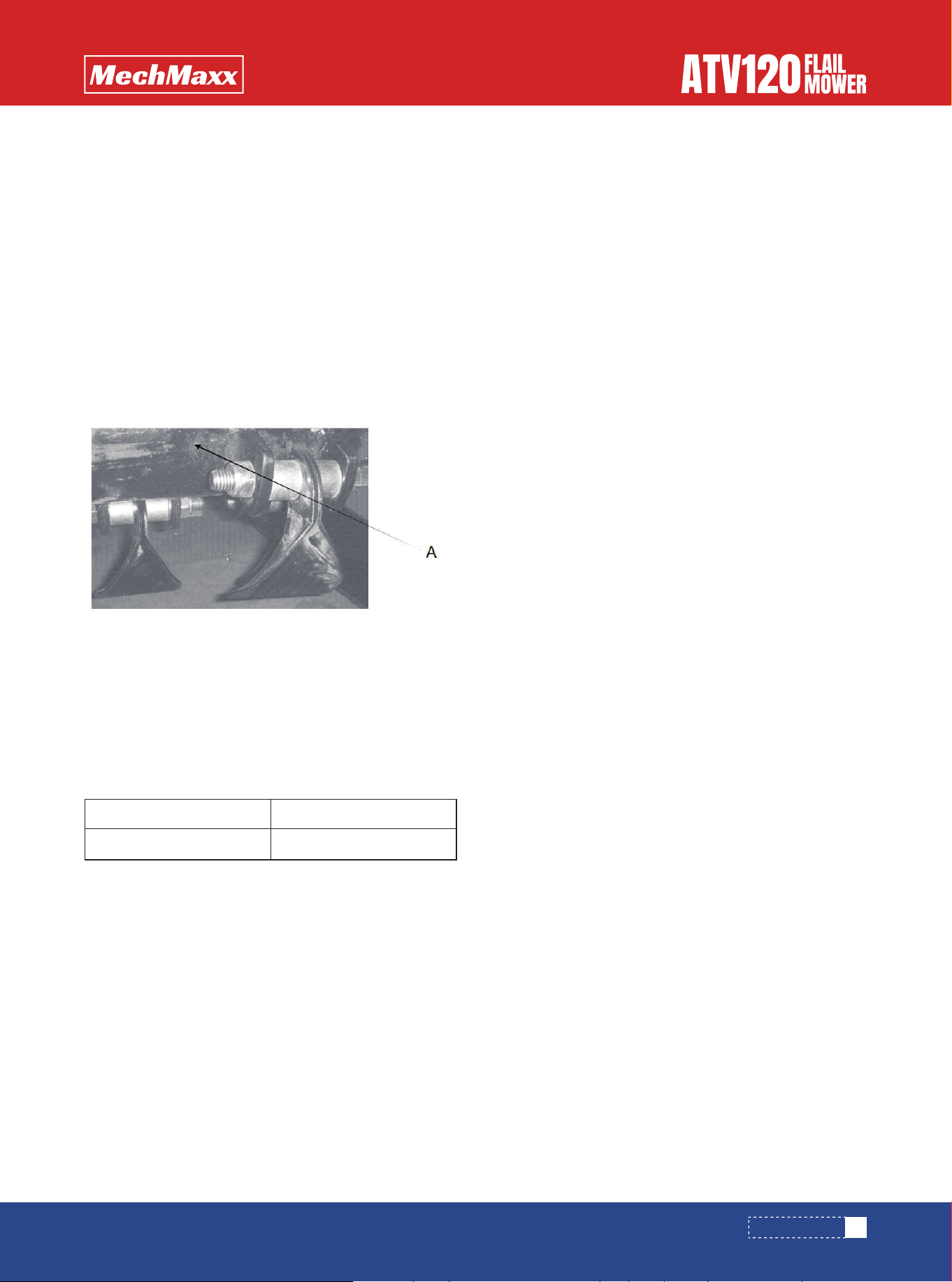
The AT range has "Rock" knives designed to last a long
time. The standard knives are double edged for even
longer life. However, when breaking or losing a knife, it is
important to replace it immediately. Failure to do this can
cause serious unbalancing problems. (Always use spare
parts)
At the time of replacement, the opposite knife on the
rotor should be checked for wear. If it is partially or well
worn then it should be changed to maintain an accurate
weight balance.
When the first cutting edge is becoming blunt, the whole
set off ails should be turned around. (Using blunt knives
will reduce the cutting efficiency and increase fuel
consumption).
Replacing or reversing the knives follows this simple
procedure:
ROTOR FLAIL MAINTENANCE
VISUAL CHECK
TYRE PRESSURES
ROTOR BEARING INSPECTION
WHEEL BEARING INSPECTION
11
www. mechmaxx.com
MAINTENANCE
22×1100 -8
16.5×6.50 -8
7 – 10 PSI
28 PSI (Max)

12
www. mechmaxx.com
A. Ensure mower engine has stopped and the knives have
stopped rotating.Switch of the fuel tap and let the
machine cool down for 5 minutes. Remove the spark plug
to ensure the engine cannot be started.
B. Raise the mower to its max cutting height.
C. Carefully raise the draw bar to an incline position, so
that the height adjuster bar at the rear of the mower
takes the weight. NB: Do not attempt this with the
wheels behind version; raise the front jack to its max
height.
A. Slacken and take out the shackle bolt.
B. Replace or turn around blades (Note the direction of
rotation)
C. Replace shackle bolt securely, but still allowing the
shackle to swing on the fixing bush.
NOTE:Never use cracked or repaired shackles when
replacing knives. If the shackle fixing has become
damaged or worn, replace with new parts
MAINTENANCE
13
www. mechmaxx.com
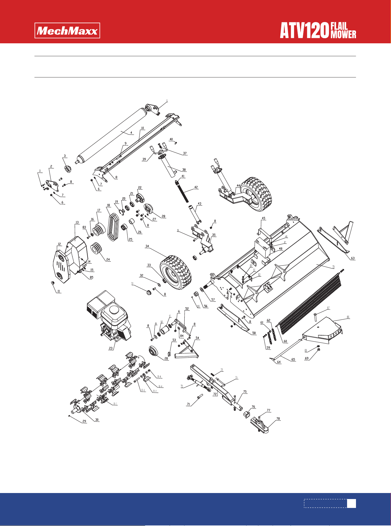
PARTS DIAGRAM
PARTS DIAGRAM

14
www. mechmaxx.com
PARTS LIST
PARTS LIST
REF DESCRIPTION QTY
1
2
3
4
5
6
7
8
9
10
11
12
13
14
15
16
17
18
19
20
21
22
23
24
25
26
27
28
29
Bolt M8*25
Rear roller connection plate (L)
Bearing UC205
Rear roller
Rear roller connection plate (R)
Nut M12
Washer 12
Boltm12*30
Bolt M12*60
Rear open door
Rubber cover 25
Up belt cover
Belt cover
Bolt M8*16
Washer 8
Cover for pully
Up pulley
Belt SPB1016
Inner circlip
Out circlip
Bearing 6007
Clutch
15HP engine
Down pulley
Power lock 35*60
Bushing for oil seal
Spring washer 12
Bearing UC207
Grease nipple M8*1
Blade Axle assembly
Blade Axle
Bolt M12*80
bushing
hammer
Lock Nut M12
Tire cover
Plate for tire
Bearing 6205
Tire
Left wheel frame
Bolt M12*80
Twisted Plunger
Out tube weldment
Spindle weldment
Bolt M8*25
Bearing 51104
Inner lead screw
Inner tube weldment
Right wheel frame
battery plate
Lock Nut M8
Bolt M8*80
Battery
washer
bearing 16005
tension roller
tension roller weldment
Square Rubber cOVER
8
1
2
1
1
34
33
27
2
1
1
1
1
4
4
1
1
3
1
1
2
1
1
1
1
1
10
2
4
1
1
24
56
28
28
2
2
4
2
1
2
2
2
2
2
4
2
2
1
1
2
2
1
1
2
1
1
2
REF DESCRIPTION QTY
30
30-1
30-2
30-3
30-4
30-5
31
32
33
34
35
36
37
38
39
40
41
42
43
44
45
46
47
48
49
50
51
52
53

15
www. mechmaxx.com
PARTS LIST
Protection plate
Grease nipple M6*1
Lock Nut M30
Washer 30
Skid left
Nut M10
Hanging Rod
bushing
Chain ∮6
Skid right
Clip 5*40
Connection bar
Linkage weledment
Bolt M16*90
Washer 16
Locking nut M16
Connection bar
Bolt M16*60
Linkage weledment
Spring
Pin
Connection bar A
Bush
Bolt M12*70
trailer bar
Mower Deck
Lock Nut M10
Washer 10
Bolt M10*45
Bolt 3/8-24UNC×35
Big wash 12
Bolt M8*25
2
2
2
2
1
4
1
57
56
1
2
1
1
1
3
3
1
2
1
1
1
1
2
2
1
1
4
4
4
1
1
2
REF DESCRIPTION QTY
54
55
56
57
58
59
60
61
62
63
64
65
66
67
68
69
70
71
72
73
74
75
76
77
78
79
80
81
82
83
84
85