
Operator’s Manual
www.mechmaxx.com
WARRANTY
WALK BEHIND
FLAIL MOWER

In order to make you use this product more safely, this book records the knowledge of use method, maintenance and
inspection in detail. Please use it correctly on the basis of reading and understanding.
After reading, please keep this manual properly for next use.
In addition, when lending or transferring the machine to others, please give the instructions to the other party.
This manual uses important safety matters! The warning words are divided into the following categories.
In addition, in order to improve the quality, performance or safety of the machine, the parts used are sometimes
changed. At this time, the contents and illustrations of this book may be inconsistent with the machine. Please under-
stand.
A machine is a machine used to cut grass.
Please do not use it for operations other than mowing.
When the machine is used for other than mowing operations or when the machine is modified, it does not belong to the
warranty object.
FRIST
Please observe.
DANGER
Express
1
www.mechmaxx.com
TABLE OF CONTENTS
Very dangerous warning.
Failure to follow the instructions will cause casualties.
THANK YOU FOR PURCHASING OUR PRODUCTS
ABOUT THE PURPOSE OF THE MACHINE
WARNING
Warning of potential danger and failure to follow the instructions may lead to casualties.
BE CAREFUL
Failure to follow the instructions may cause moderate and mild accidents.

FOR SAFE OPERATION
SPECIFICATIONS
TABLE OF CONTENTS
TYPE OPERATION
3
4
5
7
ABOUT DISPLAYING LABELS
9
BEFORE USE
OPERATION METHOD
16
MAINTENANCE METHOD
20
HANDLING IN CASE OF FAILURE
27
PARTS DIAGRAM(SFM27W)
30
PARTS LIST(SFM27W)
31
PARTS DIAGRAM(SFM27T)
41
PARTS LIST(SFM27T) 42
16
PREPARATION BEFORE OPERATION
16
MATTERS NEEDING ATTENTION
17
OPERATION METHOD
19
KEY POINTS OF TREATMENT
22
KEY POINTS OF TREATMENT
23
OIL FEEDING AND FILLING GAUGE
25
INSPECTION AND CLEANING METHODS OF ALL
PARTS
26
INSPECTION AND ADJUSTMENT OF EACH PART
4
METHODS OF SAFE OPERATION
COMMENCEMENT INSPECTION
4
5
MOWING OPERATION
PR ESERVATION
6
9
ABOUT THREE GUARANTEES AND SERVICES
ABOUT TERMINOLOGY
9
10
ROLE OF EACH PART
10
NAME OF EACH PART
11
DRIVING METHOD
11
INSPECTION BEFORE OPERATION
11
OPERATION CHECKLIST
12
START THE ENGINE
13
FORWARD, TURNING AND PARKING METHODS
14
TURNING METHOD
14
METHODS OF LOADING AND UNLOADING VEHICLES
PLEASE OBSERVE THE FOLLOWING ITEMS DURING
USE
8
2
www.mechmaxx.com
TABLE OF CONTENTS

SPECIFICATIONS
Engine
Engine Type
Engine Displacement
Horsepower
Start
Fuel Tank Capacity
Engine Oil Capacity
Cutting Width
Cutting Height
Blades
Transmission
Forward Speed
Reverse Speed
Walking Mode
Drive Tire Size/Track Size
Front Caster
Productivity
Max. Gradeability
Handlebars
LONCIN G300FD Gasoline Engine
Single Cylinder, 4 Stroke, Air-Cooled, OHV
302 cc
10 HP
Electric Start (battery included)
1.59 gal (6L)
0.25 gal (0.95L)
27 in
0.8 - 3.2 in
38pcs "Y" blades
Transaxle 3 Forward / 1 Reverse Speed
1.34mph, 2.46mph, 3.11mph
1.12mph
Drive Wheel
15 x 5.00 - 6 Pneumatic Tire
2.50 - 4
Up to 0.84 Acres per hour
30°
Height, Left and Right Adjustable
LONCIN G300FD Gasoline Engine
Single Cylinder, 4 Stroke, Air-Cooled, OHV
302 cc
10 HP
Electric Start (battery included)
1.59 gal (6L)
0.25 gal (0.95L)
27 in
0.8 - 3.2 in
38pcs "Y" blades
Transaxle 3 Forward / 1 Reverse Speed
1.3mph, 2.05mph, 2.8mph
1.06mph
Crawler Track
180W x 60P x 25L
2.50 - 4
Up to 0.76 Acres per hour
30°
Height, Left and Right Adjustable
Model SFM27W SFM27T
3
www.mechmaxx.com
SPECIFICATIONS
The safety matters are divided into three stages
Please carefully read and understand the safety operation. In addition, there are the same instructions in the text. Please
be sure to follow them
After carefully reading the instruction manual and machine label, always give priority to safe driving.
Failure to follow the instructions of the recorded contents will not only have a bad impact on the function of the
machine, but also cause personal accidents.
in a flat place, turn off the traveling clutch and stop the engine.
if the labels on the machine are not available, dirty or can not be seen clearly, they need to be replaced.
clean the engine, exhaust pipe and oil tank.
check whether the insulation of the line is damaged.
when checking the oil quantity, wait until the engine cools down.
confirm whether the clutch and operating lever can work normally.
when adding gasoline, stop the engine first and stay away from the fire source.
do not replenish fuel when the engine is hot.
do not modify the machine.
FOR SAFE OPERATION
Please observe the following items before work.
Key points of safe operation.
Inspection preparation
METHODS OF SAFE OPERATION
COMMENCEMENT INSPECTION
4
www.mechmaxx.com
WARNING
Please don't operate the machine
people with alcohol smell.
pregnant people.
persons under the age of 16.
unskilled drivers without instructors.
unable to work due to overwork, illness, in fluence of drugs and other reasons.
A person who normally operates a machine.
operators should pay attention to their health and ensure proper sleep and rest.
Danger Warning Be careful
WARNING
Use Protective Gear.
Use protective eyewear and clothing when operating in order to a void personal injuries.
WARNING
Please use the machine with this when lending it to others.
Lend the instructions to others to explain the machine.
Until they can operate the machine smoothly.
FOR SAFE OPERATION

Start the engine
5
www.mechmaxx.com
check the strength and width of the ladder. The length should be greater than 4 times the height of the car, Use non
slip ladders.
place the ladder flat on the carriage and hook it with a hook to prevent the ladder from falling down.
confirm the surrounding environment and keep people away from the machine.
use "operation gear 1" for loading and "backward" for unloading.
do not change direction or speed on the ladder.
Loading and unloading of automobile transportation
TYPE OPERATION
MOWING OPERATION
transport by car on the road and at night.
confirm the surrounding environment when moving forward and turning.
do not walk with the cutter on.
do not put people or things on the machine.
turn at low speed when walking.
back up is to confirm the rear environment.
do not drive, stop or turn sharply.
do not let go when operating the machine.
Driving operation
when starting forward and turning around, slow down with low gear.
when going downhill, slow down and use the brake provided by the engine.
do not turn left or right, stop or change speed on steep slopes.
when giving way to the opposite vehicle, don't pull too close to the side.
do not walk on muddy ground or overgrown with weeds.
Narrow agricultural roads, uneven roads and driving on ramps
Parking
in a flat place, put the traveling clutch in the "cut" position and turn off the engine.
never stop on a slope.
Enter the mowing area
low speed, right angle ridge climbing.
use ladders on ridges, ditches and steep slopes, and pay attention to your feet when moving forward and backward.
drive slowly and do not collapse the ridge.
do not change direction on the ladder.
do not enter or leave the mowing area with the cutter on.
install all covers before starting.
put the shift lever in the "n" position, and put the travel clutch and the cutter clutch in the "cut" position.
put each operating lever in "n" or "cut".
make sure there are no obstacles around.
keep people around away from the machine.
if starting in the house, please open the windows and doors for ventilation.
FOR SAFE OPERATION

6
www.mechmaxx.com
PR ESERVATION
After one day's homework
stop at a flat place, put the traveling clutch on the "cut" and turn off the engine.
do not park near inflammables.
clean the surroundings of engine, exhaust pipe, storage battery and oil tank.
Long term preservation
regular inspection every season.
drain the gasoline from the oil tank, oil circuit switch and carburetor.
put it on a flat place, stop the engine and fix the gear of the track.
cover the machine after the engine has cooled down.
remove the connector of the battery and take out the battery.
Mowing operation
do not work near people, livestock, cars and houses (ensure a distance of 10 meters).
turn at a low speed and make sure you follow your feet.
leave room for turning around on the ridge.
when there are dense weeds, remove the stones and other obstacles in front before mowing.
when retreating, use low gear to confirm that there are no obstacles at the rear and at the foot, and then pass slowly.
this mower has no headlights. Do not work or move at night or in dark places.
don't work hard when you feel tired. You need a proper rest.
when cleaning the mud and residual grass in the cutter cover, turn off the engine and park the car in a flat place for
inspection.
Slope operation
danger of rollover on slopes above 25 degrees. Please do not work (may also cause engine failure).
in order to ensure the safety of your feet, please wear non slip shoes.
in uneven or rocky places, the machine will enter at an inclined angle, At this time, we need to move forward at a low
speed.
mowing shall be carried out at the place with contour line and small turning angle.
the front wheels are fixed with pins.
FOR SAFE OPERATION
ABOUT DISPLAYING LABELS
7
www.mechmaxx.com
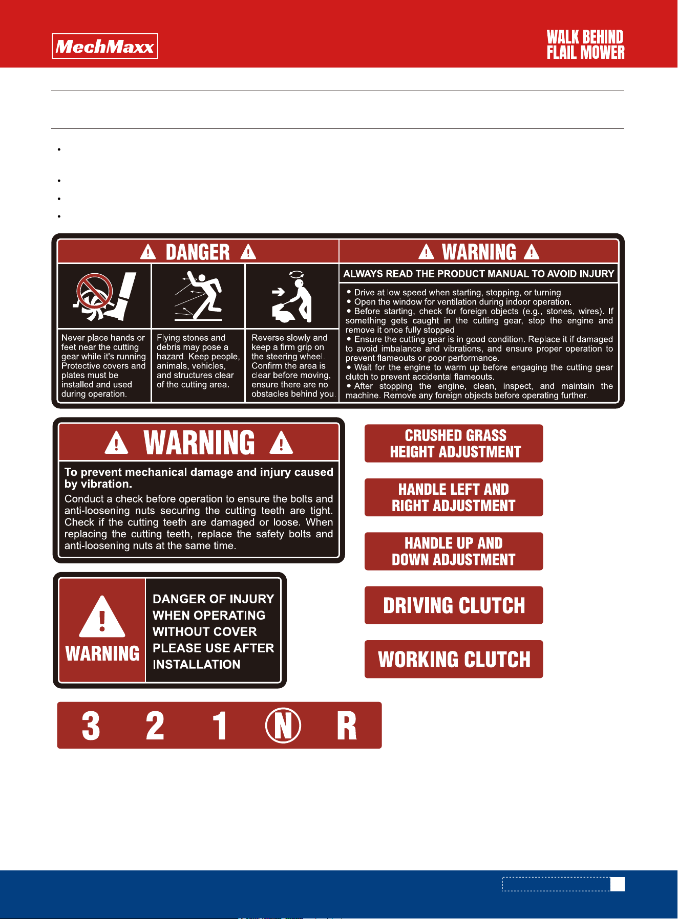
The machine is attached with labels (danger label, alarm label, attention label) describing various safe operation
methods near each operating device.
Please read the instructions of each label carefully and follow them.
In addition, if the label attached to the machine is damaged and cannot be read, or when the labeled parts are replaced,
Please order a new label from the "supplier" and purchase and replace it.
ABOUT DISPLAYING LABELS

8
www.mechmaxx.com
PLEASE OBSERVE THE FOLLOWING ITEMS DURING USE
1. Please do not tear off the applicable label of independent regulation.
2. Please check and maintain the engine according to the operation manual.
3.If you need to adjust or replace the carburetor, please consult the "supplier".
The amount of exhaust gas shall be managed within the specified value. However, if the carburetor affecting the mixing
ratio of inhaled air and fuel is adjusted, the engine is poorly prepared, and the inappropriate carburetor is replaced, the
amount of exhaust gas may exceed the specified value. Please note.
ABOUT DISPLAYING LABELS
BEFORE USE
9
www.mechmaxx.com
ABOUT THREE GUARANTEES AND SERVICES
ABOUT TERMINOLOGY
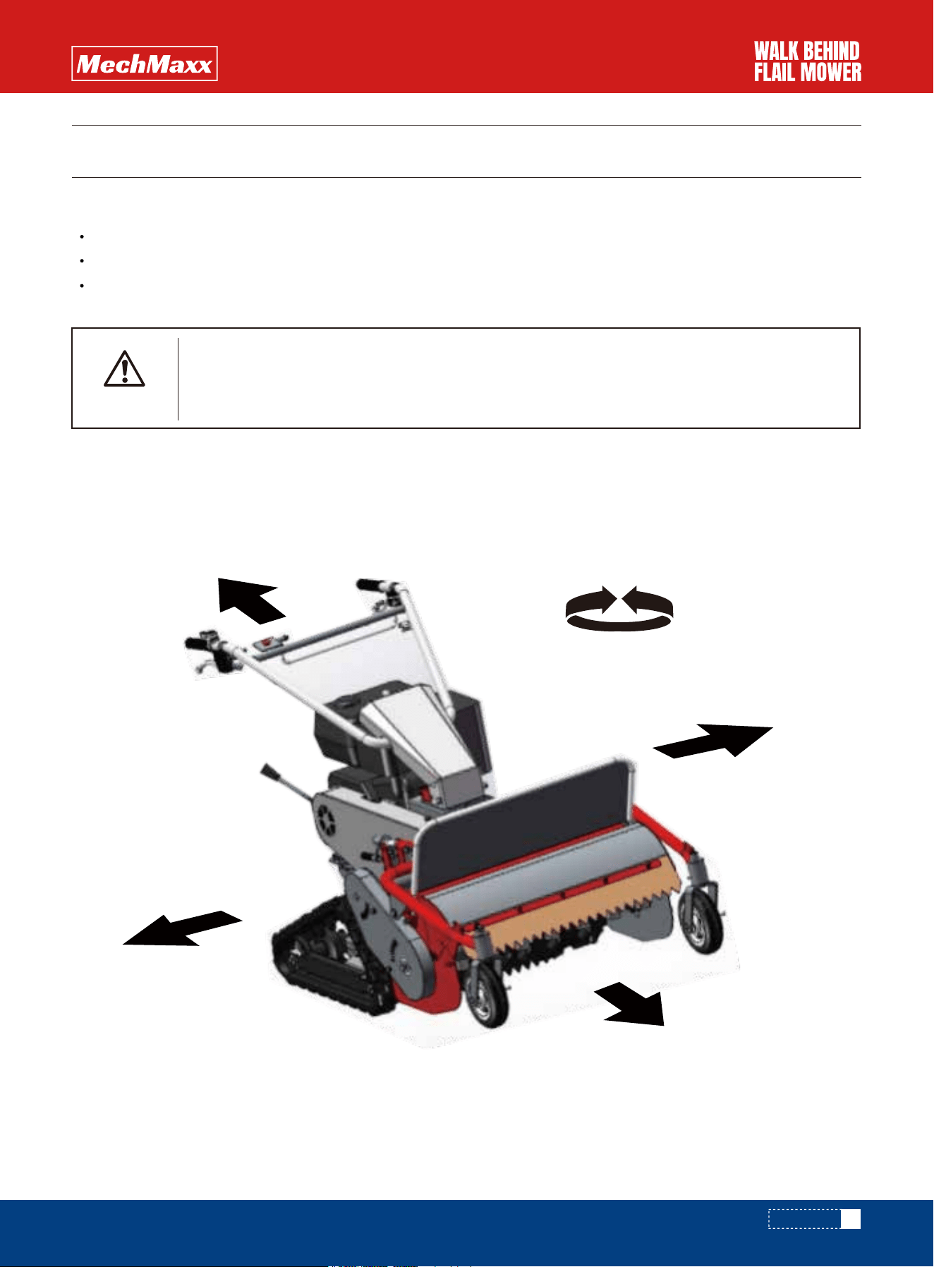
The terms "front and back, left and right, right turn and left turn" used in this manual are shown in the figure (in the
running state, the decision before and after operation s hall be made after taking the operator as the center.)
about the purpose of the machine
please use the machine in weeding.
please note that the use or modification of the machine in operations other than the purpose of use does not belong
to the warranty object.
WARNING
right
Left
front
after
Turn right
clockwise
Turn left
counterclockwise
Please use the machine in weeding.
Do not modify the machine. After the transformation, not only can not play its original func-
tion, but also may cause personal accidents.
BEFORE USE
10
www.mechmaxx.com
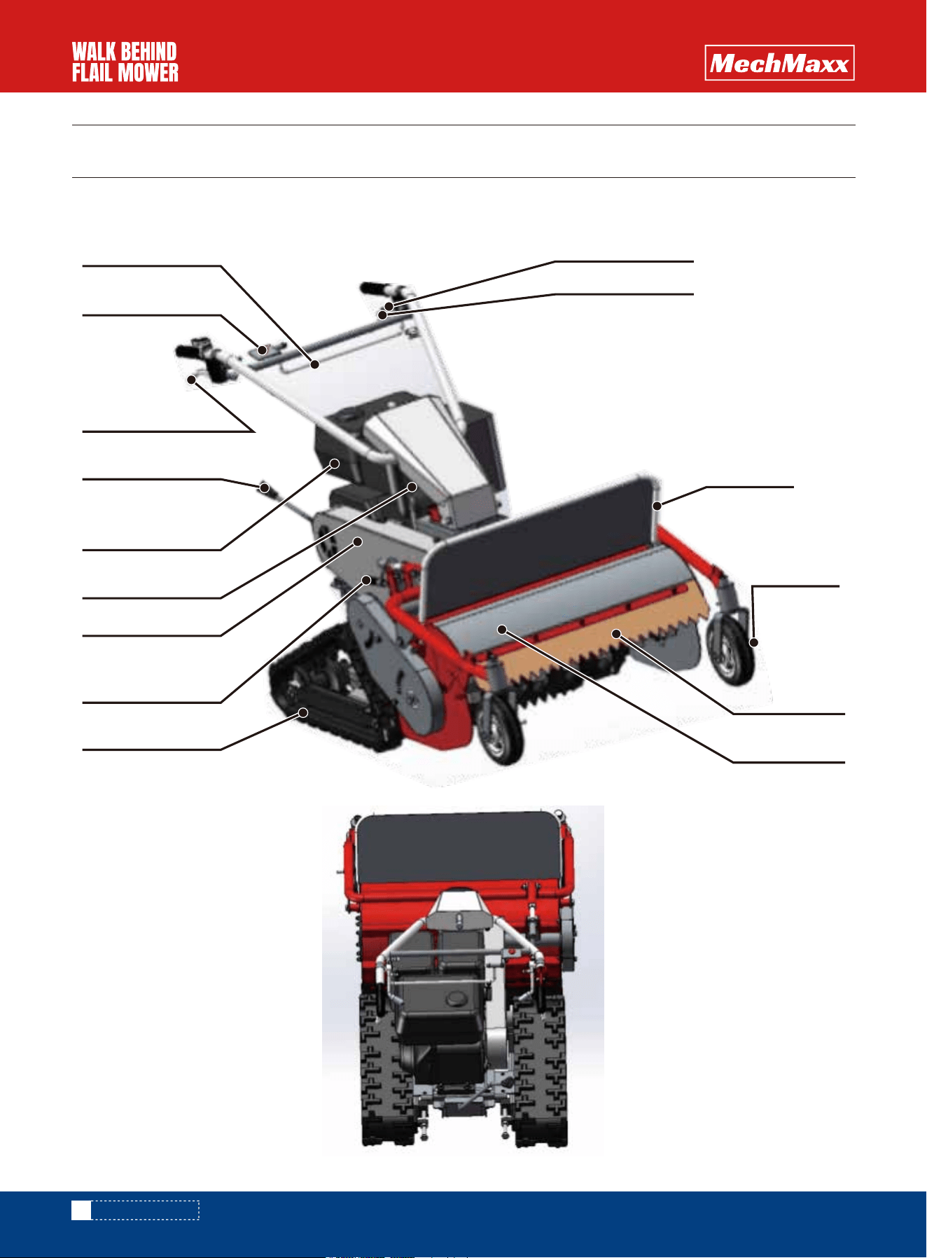
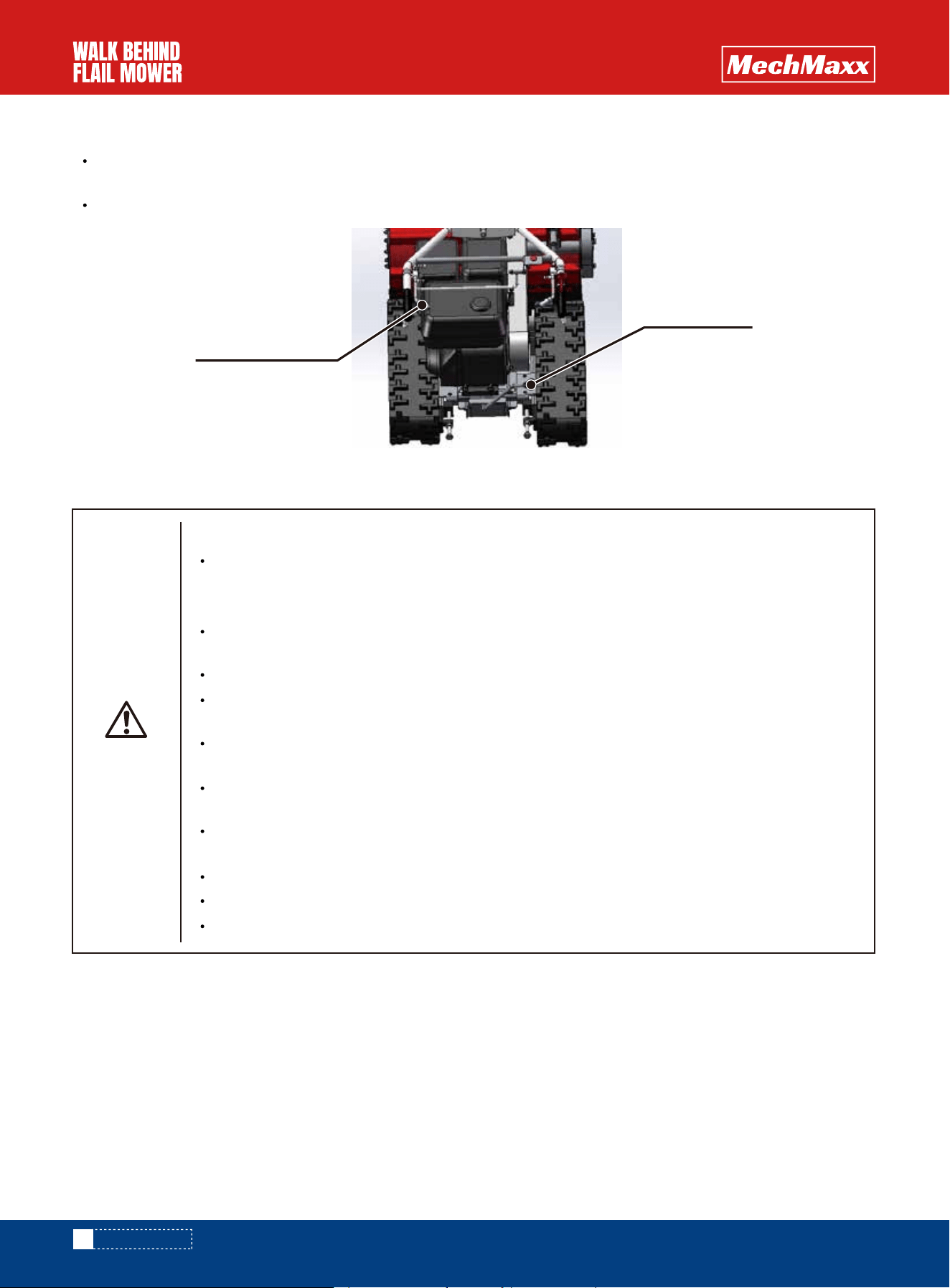
NAME OF EACH PART
ROLE OF EACH PART
ROLE OF EACH PART
Cutter clutch lever
Travel clutch lever
Left steering clutch
Cutter cover
front wheel
protection cover
Front cover
Emergency stop switch
Right steering clutch
The gear lever
tank
exhaust pipe
Belt cover
Cutter height
adjustment handle
track
Inspection position management
Top up the oil
Replenish unleaded gasoline
Replace the pipe, replace
the pliers and fix it tightly.
Add proper amount of oil
Tighten the mounting part
Replace the cutter
Clean up the accumulated
mud and grass
Replace the air filter element
clear
clear
clean
Engine oil volume
Oil circuit switch
Oil tank
Air filter element
Pull plate air inlet
Gasoline pipeline
Cutter
Cutter cover
Refuel all parts
Engine, exhaust
pipe, battery, fuel
tank accessories
Is the oil in the middle of the dipstick
Is there fuel for the operation
Clean whether the air filter element is dirty
Is the air inlet blocked
Mixed with water and garbage
Whether the filter element is blocked
Whether the fuel is leaked, aged, damaged, and
whether the pliers at the joint are loose.
Is the cutter really fixed
Whether the cutter is worn and consumed
Is there any accumulation of grass and mud
Is there any accumulation of grass and ash
Is there no oil
11
www.mechmaxx.com
INSPECTION BEFORE OPERATION
OPERATION CHECKLIST
DRIVING METHOD
DRIVING METHOD
For safe operation, please refer to the "pre operation Checklist" before operation every day.
WARNING
To prevent injury accidents
During refueling and inspection, please put the machine in a flat place and stop the engine
before operation.
do not be close to the fire source when refueling. Fuel fire is an important factor leading to fire.
after adding oil, close the cover and wipe the oil leaked out.
oil leakage caused by aging of oil tank or oil pipe or injury is the cause of fire. It needs to be
checked before and after operation. If the oil pipe is damaged, it needs to be replaced in time.
To prevent burns and fires
Do not add oil when the engine is running or when the engine is very hot.
DANGER
Befo rework
12
www.mechmaxx.com
START THE ENGINE
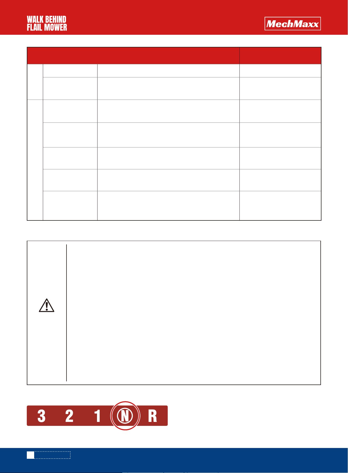
1.Shift lever in "n" (neutral)
DRIVING METHOD
WARNING
To prevent injury accidents
Park the machine in a flat place and remove the garbage and combustibles around the
exhaust pipe.
When the brake is turned on, the handset will not move by itself even if the hand leaves the
direction.
Install all the covers removed during inspection.
When starting the engine, put the gear lever of the gearbox on the " n", and put the travel
clutch lever and the cutter clutch lever on the "cut" position.
The outlet position of the exhaust pipeshall not face inflammables.
When starting the machine in the house or greenhouse, be sure to open the window and door
to prevent tail gas poisoning.
Do not touch the exhaust pipe before it cools down with the engine. Touching it when
it is hot will cause burns.
When pulling the disc, do not ouch the spark plug cover or insulating wire. If you touch it, you
will feel an electric shock.
Inspection position management
Replace the protective cover
Check the abnormal parts
and deal with them
Check the abnormal parts
and handle them.
Check the abnormal parts
and handle them.
Check the abnormal parts
and handle them.
Check the abnormal parts
and handle them.
Add proper amount of oil
protection cover
Each operating
lever and stay wire
Travel clutch lever
Engine control
lever
Engine switch
Cutter clutch lever
Left and right
steering clutch
lever
Whether there is missing or deformation
Will the travel clutch be disconnected
Is the parking brake easy to use
Can the operation be normal
when slowly adjusting the operating lever
Will the engine stop
when the engine switch is operated
Whether the left and right steering clutch can be d
isconnected
Will the cutter clutch be disconnected
Whether it can move smoothly; Is there any oil
After engine start
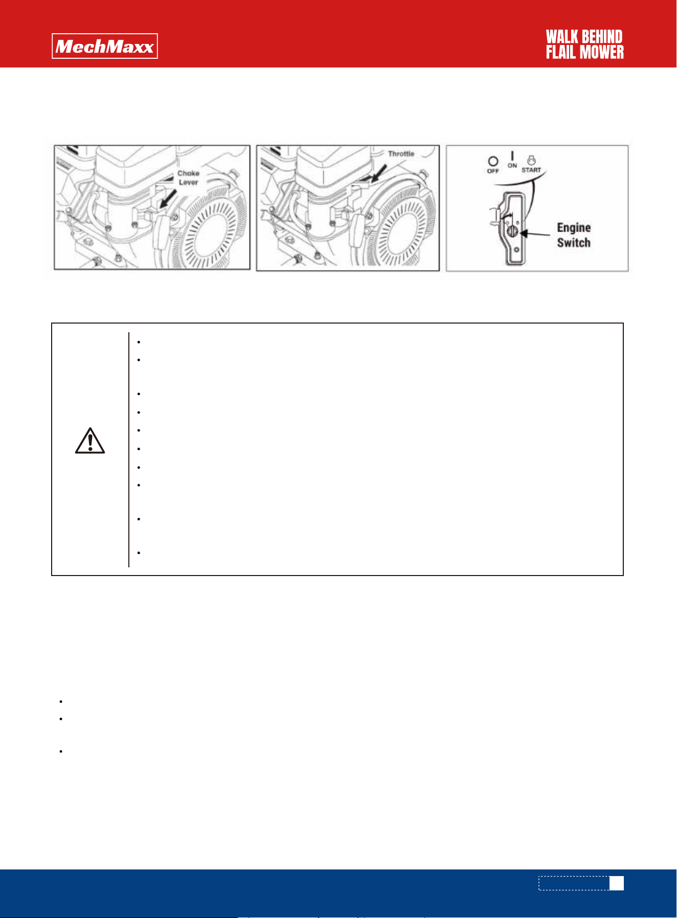
2. Start Gas Engine
-Refer to the instructions in the engine manual for proper startup procedures. Ensure the engine exhaust is not direct-
ed toward any flammable materials to prevent fire hazards.
1.Adjust the engine control lever to low (low speed).
2.Adjust the travel clutch lever to off.
3.Adjust the gear lever to the appropriate gear according to the working environment.
4.Adjust the travel clutch to"on"and start the machine.
5.Adjust the engine control lever to increase the engine speed.
put the shift lever and traveling clutch at the "off" position before operation.
when the gear lever is difficult to operate, do not operate it hard. First close the traveling clutch again, and then
operate the gear lever.
when changing gears of "n" (neutral) → "back" and "back" → "n" (neutral), press down the gear lever and move it
again.
13
www.mechmaxx.com
FORWARD, TURNING AND PARKING METHODS
KEY POINTS OF TREATMENT
The way forward
When retreating, make sure there are no obstacles behind or around
First adjust the travel clutch and cutter clutch to "off", and then start the engine or change
the gear
Don't use mobile gear 3 on slopes or bad terrain
Do not move the machine by turning the cutter
When going down the slope, please use the reverse gear
In case of emergency, put the traveling clutch in the "cut" position and stop the machine
When not mowing, adjust the cutter clutch to the "off" position
When the machine starts, after confirming the surrounding environment, start slowly at
low gear
When turning, turn down the engine throttle, confirm the surrounding environment, and
then turn
When walking at high speed, do not operate the left and right steering clutches.
WARNING
DRIVING METHOD
The car cannot be overloaded and the machine cannot be exposed from the car compartment.
Hold the handbrake and shift the gear into "forward", "1" or "reverse",
Please stop the tire.
The height of the ladder shall be greater than 4 times that of the car compartment.
The maximum load is greater than that of the machine. Use a ladder with anti-skid.
Align the ladder with the left and right tracks of the machine and put it on the carriage horizontally to prevent sideslip
and heel separation.
14
www.mechmaxx.com
TURNING METHOD
About automobile aluminum ladder
METHODS OF LOADING AND UNLOADING VEHICLES
To prevent injury accidents
Choose a flat and hard place where the ladder does not tilt. The car pulls the handbrake, the
engine stops, and the gear is in "forward", "1" or "reverse". Please stop the tire.
Please use the aluminum ladder with strength,
width (the width of the track without falling off), length (more than 4 times the height of the car)
and anti-skid, hook and other functions.
Put the hook of the ladder on the carriage to ensure that the hook will not disengage.
Please load and unload under the supervision of auxiliary personnel. Please keep people away
from the machine.
When loading and unloading, please lift the cutter part and do not let the cutter part hang on the
aluminum ladder.
Shift to "forward" and "1" during loading and "reverse" during unloading. Please drive at a low
speed to ensure safety under your feet.
When loading or unloading the car on the aluminum ladder, do not operate the left and right steer-
ing clutch, walking clutch and gear lever. There is a risk of the machine falling during sharp turns
Please do not load or unload the truck when the cutter is rotating.
Please do not stand in front of the machine for guidance.
Truck please use the car with no roof on the container
WARNING
Travel clutch lever
The gear lever
When changing the direction of the machine, set the engine control lever to low (low speed) and hold the steering
clutch lever on the rotating side.
With another pinch, the left and right brakes will start and the machine will "turn".
DRIVING METHOD

15
www.mechmaxx.com
place the engine control lever in the "low" position.
operate the shift lever along the guide groove to make it in the position of "1" or "R".
use "forward" gear 1 for loading. Lift the front end of the cutter part and be careful not to hang it on the aluminum
ladder.
when unloading, use the " reverse" gear for loading. Lift the front end of the cutter part and be careful not to hang it on
the aluminum ladder.
after loading, turn off the engine and put the traveling clutch on the "cut".
Operation method of the machine
DRIVING METHOD
1. Occasions with small stones
2. When the cutter cuts the soil
3. In uneven places
4. Wet grass, long grass and places with dense grass (cut twice)
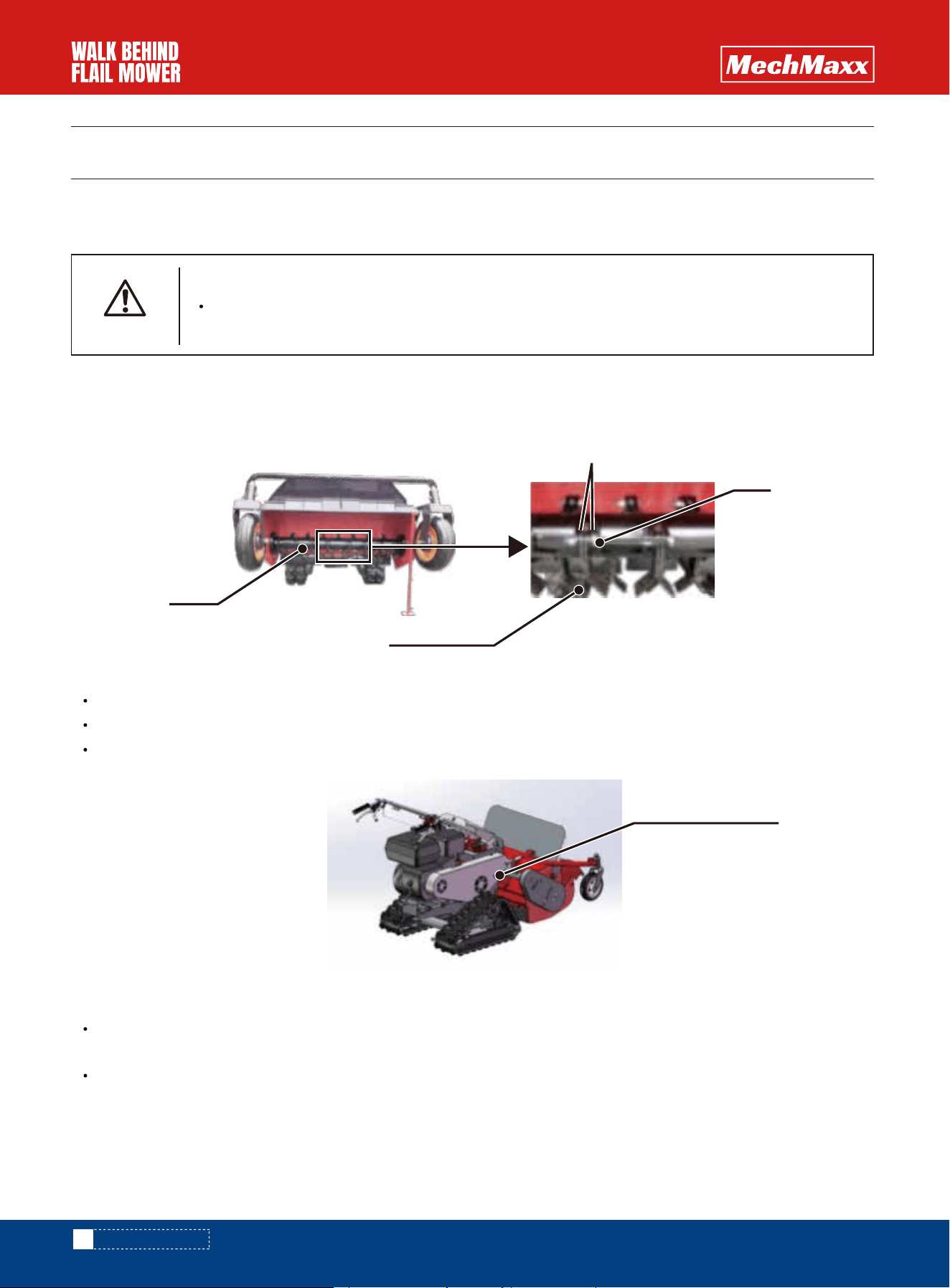
The cutter is installed on the connector with two blades facing back to back and fixed with screws and nuts. Each time,
confirm whether the nuts are fastened, and the bolts expose more than two threads from the other end of the fastening
nut. The cutter can rotate on the connector
OPERATION METHOD
OPERATION METHOD
16
www.mechmaxx.com
Install the cutter
Cutter height adjustment
PREPARATION BEFORE OPERATION
MATTERS NEEDING ATTENTION
To prevent injury accidents
If you continue to use the cutter with incomplete, damaged or extremely worn, it will cause vibra-
tion damage to the machine, which is very dangerous. Please check it before operation.
WARNING
Rotate the cutter height adjustment handle so that the front wheel will not float up and down
Adjust the cutter height handle to the left to reduce the cutter height
Adjust the cutter height handle to the right to raise the cutter height
slightly increasing the height of the cutter can reduce the wear of the cutter and the cutter can be used for a longer
time.
please raise the cutter for the following occasions
Cutter
Fastening nut
Connector
Bolt
Crushed grass
height adjustment

Adjust the height of the handle according to the height of the operator
It can adjust several heights according to the position of the handle groove
Lower the engine speed.
Shift lever to operation "1" or "back".
Put the walking clutch on the "in" and move forward or backward slowly.
Operate the travel clutch lever to the "cut" position, and the machine will stop.
17
www.mechmaxx.com
OPERATION METHOD
Handle height adjustment
Methods of entering the workplace
OPERATION METHOD
To prevent injury accidents
Stop turning the cutter when entering the workplace or crossing the ridge.
When climbing a slope, please use the "forward" and "1" right angles to climb up, and when going
downhill, please use the "reverse" gear.
Please use ladders when you are on high ridges, steep slopes or deep ditches.
When the machine is on the ladder, do not operate the travel clutch lever, left and right steering
clutch and shift lever.
Make sure not to break the ridge and walk slowly.
When retreating, please make sure there is no ditch or obstacle before driving.
WARNING
Handle height adjustment
Cutter clutch lever
The gear lever
Travel clutch lever
Walking speed
18
www.mechmaxx.com
OPERATION METHOD
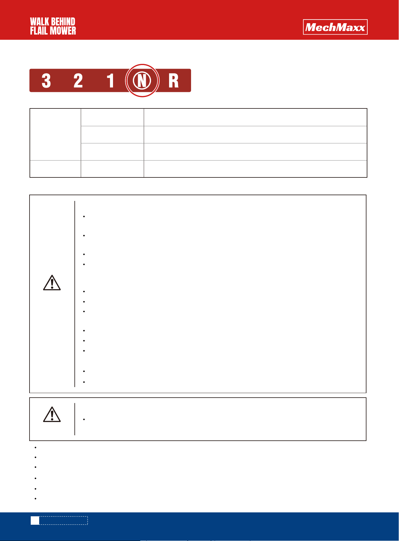
Selection method suitable for working speed
Skilled working methods
forward
back off
《 1 》 Mobile walking, operation, loading, crossing ridge
《 2 》 Mobile walking
《 3 》 Mobile walking
《 R 》 Mobile walking and unloading
To prevent injury accidents
When the blade is entangled with grass, please shut down the engine quickly and clean the grass.
If there is grass in it, it will cause failure
BE CAREFUL
To prevent injury accidents
Stones or other foreign matters mayfly out during operation. Please ensure to keep a distance of
10 meters from people, livestock, cars and houses.
Set up a warning line in the operation area, let people not walk within 10 meters, and set up
dangerous warning signs
Make sure there is no one in and out of kindergartens, schools and parks before doing homework.
Remove stones and other foreign matters before operation, and erect marker posts in obstacles,
side ditches, weak places, concave convex places and places with poor vision. Be careful not to
approach them during operation
Do not stand in front of the machine for confi mation
Do not work on an angle slope of more than 25 degrees
When turning or retreating, please confirm the surrounding and under your feet, and do not climb
on the ridge or the edge of the dam.
Please turn down the throttle when you step back.
In case of emergency, turn offthe travel clutch and stop the machine.
When checking the of the machine during operation , be careful not to touch the
high-temperature part of the machine.
When cleaning the grass and mud accumulated in the cutter cover, please stop the engine.
This machine has no lights, so please don't work or move at night or in the dark.
WARNING
When the machine travels, adjust the engine control lever to the position of gear 2 and 3.
When the machine is working, the shift lever is adjusted to the position of "1 and 2" along the guide rail.
The traveling clutch is placed on the "in" and the machine moves forward.
Put the traveling clutch on the "cut" and the machine stops.
The cutter clutch is placed on the "in" and the cutter rotates.
The cutter clutch is placed on the cutter and the cutter stops

19
www.mechmaxx.com
OPERATION METHOD
KEY POINTS OF TREATMENT
when cutting wet grass, the grass cut inside the cutter cover is easy to pile up,accumulation will cause unreason-
able load to the machine, so please wait for the grass to dry then start working, or often clean up the accumulated
inside the cutter coverStraw residue.
when the mower is overloaded, please shift to "forward" or "1", or Increase the mowing height and cut twice or reduce
the mowing width. (wet) grass, long grass, dense grass, etc.
If the engine throttle is not adjusted to the maximum, put in the cutter clutch the engine may stall.
please operate after the cutter is fully rotated. Low cutter speed the engine may shut down or the grass may not be
cut clean.
sometimes long grass and vine like grass will be entangled on the cutter and cannot be used well cut.
when mowing on the slope, please fix the front wheel to cut the grass stably
MAINTENANCE METHOD
20
www.mechmaxx.com
Regular inspection and servicing
WARNING
To prevent injury accidents
During inspection, maintenance and cleaning, please put the machine on a flat place, put on the
parking brake, turn off the engine, and stop all parts.
The inspection and servicing around the engine shall be carried out after the engine has cooled
down
When starting the engine indoors, please open the windows and doors for regular ventilation
Please install all the removed covers before starting the engine
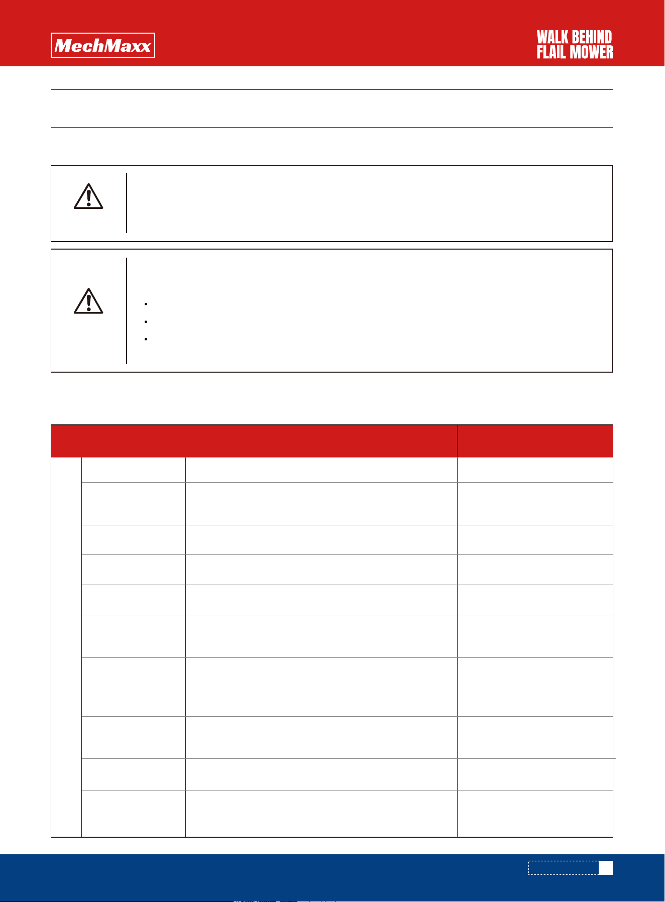
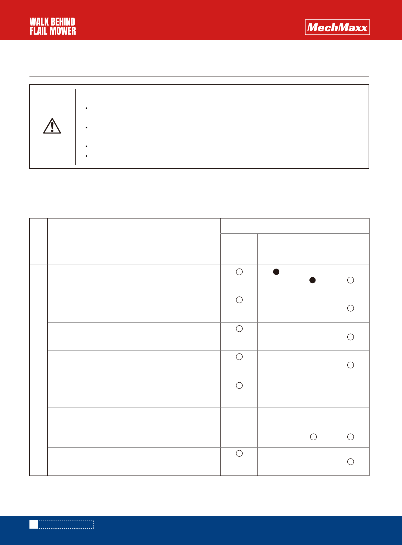
category
engine
Routine inspection and
servicing items
Engine oil
Check, supplement
and exchange
Inspection and cleaning
Inspection and cleaning
Supplement and release
Inspection and
replacement
Let go
Let go
Let go
Inspection, cleaning
and replacement
Inspection and cleaning
Air filter element
Oil circuit switch
Gasoline in the tank
Gasoline in carburetor
spark plug
Start pull plate
Deterioration and leakage
of oil pipeline
Servicing content
Before the
mowing
season
Every
30 hours
Every
50 hours
When
saving
Spot check interval
In order to play the role of the machine and work safely all the time, please check the machine according to the "regular
inspection list ", and clean, adjust and prepare it as needed.
Regular inspection list "(inspection ○, exchange ●)
Before daily
operation
Only for the
first time
Before daily
operation
Before daily
operation
Before daily
operation
Before daily
operation
Before daily
operation
MAINTENANCE METHOD
21
www.mechmaxx.com
Waste disposal after use
1. If the waste is discarded or burned at will, it will cause environmental pollution and will be punished by laws and regula-
tions. When discharging waste liquid from the machine, please catch it in a container.
2. Do not dump on the ground, rivers, lakes and oceans; When waste oil, fuel, cooling water (antifreeze), refrigerant,
solvent, filter, battery, rubber and other harmful substances are discarded or incinerated, please consult the " purchaser
" or industrial waste treatment operator for treatment in accordance with the specified rules.
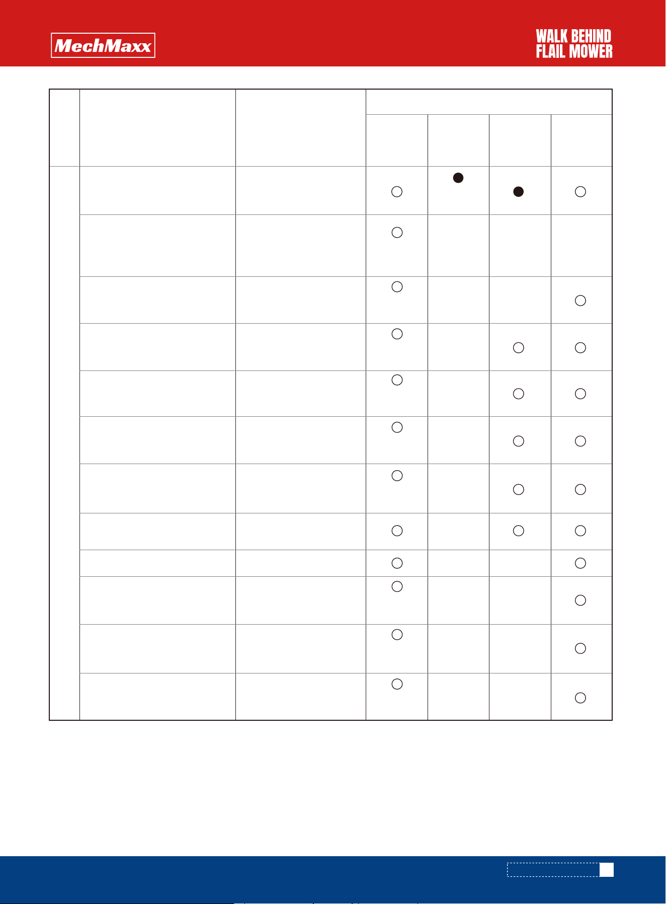
category Machine body
Routine inspection and
servicing items
Oil quantity of transmission
Action of each operating lever
Walking clutch
Cutter clutch
Left and right steering clutch
Parking brake
V-belt tightness
Loosening of screws and nuts
Installation of cutter and wear
and damage of cutter
Mud inside the cutter cover
and residues of grass
track
Refueling of each operating
lever shaft, tensioning pulley,
pulley rotation fulcrum and
stay wire
Check, supplement
and exchange
Oiling
inspect
inspect
Inspection and
adjustment
Inspection and
adjustment
Inspection and
adjustment
Inspection and
adjustment
Inspection and
adjustment
Inspection and
adjustment
Inspection and exchange
Inspection and cleaning
Servicing content
Before the
mowing
season
Every
30 hours
Every
50 hours
When
saving
Oiling
Spot check interval
Before daily
operation
Before daily
operation
Before daily
operation
Before daily
operation
Before daily
operation
Before daily
operation
Before daily
operation
Before daily
operation
Before daily
operation
Only for the
first time
MAINTENANCE METHOD
22
www.mechmaxx.com
WARNING
To prevent injury accidents
During oil, refueling and inspection, please place the machine in a flat place, stop the engine and
wait until all parts stop.
In case of abnormal noise in the rotating part and sliding part, please stop the engine first and
check and refuel after all parts stop.
DANGER
To prevent injury accidents
In order to prevent scald and fire, please stay away from the fire source when replenishing fuel.
Please do not add oil or oil when the engine is running or hot. Please do not change the oil.
Replace the fuel pipe when it is damaged or deteriorated. If there is a fuel leak, it may cause a fire.
Please wipe up the spilled fuel.
Do not touch the exhaust pipe.
Method of oiling and refueling
1. When leav ing the factory, every refueling place has been filled with oil.
2. When refueling or changing oil, please follow the "pre operation Checklist" and "regular Checklist".
3. When checking or changing oil, park the machine in a flat place.
KEY POINTS OF TREATMENT
Please add oil at each refueling point according to the specified amount.
if waste oil or dirty oil is added, it may cause machine failure. Please do not use it.
MAINTENANCE METHOD

23
www.mechmaxx.com
OIL FEEDING AND FILLING GAUGE
Oil supply and
filling place
No
Fuel tank
Unleaded
gasoline
Above
SJ level
10 W 30
10 W 30
appropriate
amount
appropriate
amount
appropriate
amount
appropriate
amount
Pre job inspection.
Supplement to the
necessary amount
・ first 30 hour
replacement
・ replace every
50 hours
・ first 30 hour
replacement
・ replace every
50 hours
・ pre job
inspection
・ with grease
fittings
appropriate
amount
80 WAbove gl4
Above SD
level
engine oil
gear oil
Butter
Engine oil
Engine crankcase
transmission case
Front wheel fork shaft
Travel clutch lever shaft
Travel clutch lever shaft
Shift lever shaft
Tensioner pulley fulcrum
shaft
Cutter height adjustment
position
Cutter clutch lever
circumference
Front cover fulcrum shaft
Front axle
Front wheel frame
fulcrum shaft
Track frame pivot shaft
type
Level
classification
SAE Viscosity
number
classification
remarksCapacity (L)
1
2
3
4
5
MAINTENANCE METHOD
24
www.mechmaxx.com
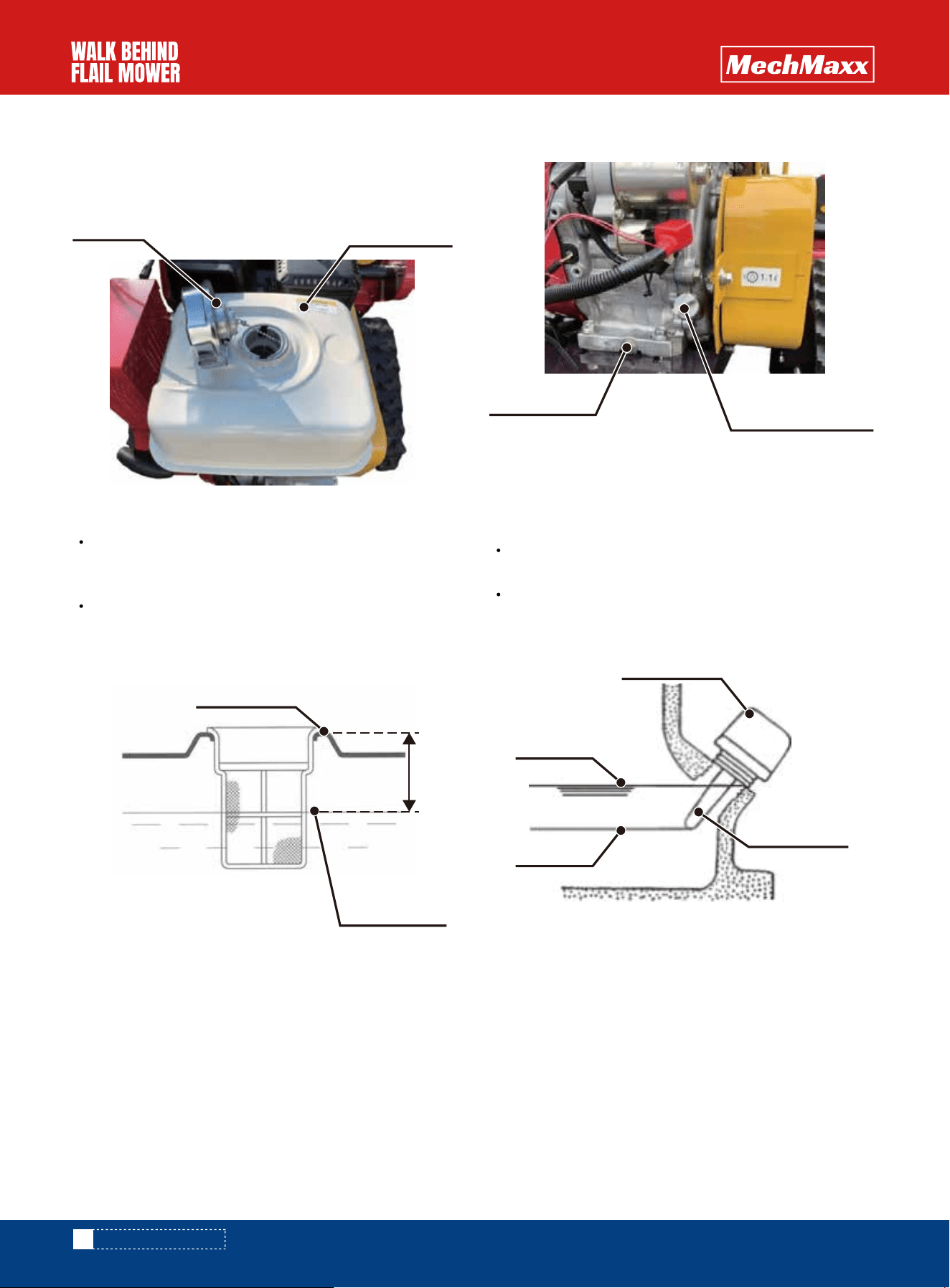
Remove the filler cap and replenish from the filler.
Fuel............... Unleaded gasoline
when refueling, the fuel shall be filtered through the
filter screen, and be careful not to mix garbage and
water.
for replenishment, please remove the refueling cover.
Cons idering the fuel expansion, please leave an allow-
ance of more than 1 inch from the port.
Check...... stop the engine at a level place, remove the
filler plug, wipe the surface of the oil inspection rod,
and then insert it. (not screwed in)
1. Refuelling 2.Inspection and replacement of engine oil
Key points of treatment
Key points of treatment
gas container
Fuel cap
Refueling limit
position
Oil drain plug
1.
Replace......
Remove the oil drain plug and drain the oil. After the
engine oil is completely drained, tighten the drain plug
and add new engine oil to the specified amount (upper
limit position)
Engine oil......
gasoline engine oil API・SJ grade or above, SAe -
10W30
2.
Refueling plug
(oil inspection rod)
Adjust the height of the cutter so that the front wheels
are grounded and the engine is in a horizontal position.
Confirm whether there is oil level between the oil
inspection rods. If it is insufficient, make up to the
upper limit.
Oil filling port
More than
1 inch
upper limit
Refueling plug
Oil inspection
rod
lower limit
MAINTENANCE METHOD
INSPECTION AND CLEANING METHODS
OF ALL PARTS
25
www.mechmaxx.com
Polyurethane foam, washed with washing oil, wrung
and dried. After dr ying, immerse in the engine oil and
screw it dry before installation.
Inside the air filter, please blow with a high-pressure
air gun or tap gently from the inside to remove dirt.
1. Clean the air filter
Key points of treatment
2. Cleaning of fuel switch
4. Inspection and replacement of cutter
3. Inspection and cleaning of spark plug
To prevent fire
Do not use gasoline to clean the
filter.
WARNING
To prevent injury accidents
Do not touch the plug cover or high�
voltage line when pulling the start-
ing pull plate. One touch will "get
an electric shock".
WARNING
To prevent injury accidents
If you continue to use the cutter
not installed in place or damaged
parts or extremely worn cutter, it
will cause vibration damage to the
machine, which is very dangerous.
Please check it before operation.
When replacing worn cutters,
please replace all (38 pieces) at
the same time. (once the rotating
balance collapses, the vibration
will increase, which is ver y danger-
ous)
WARNING
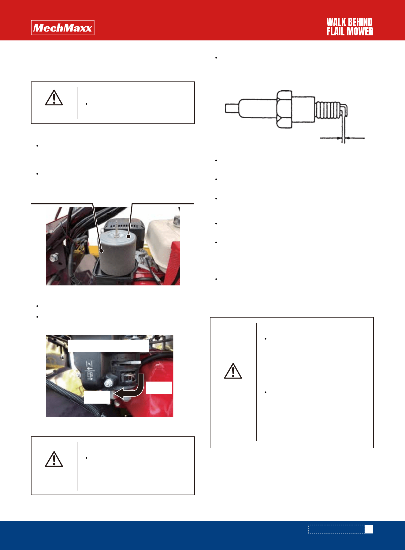
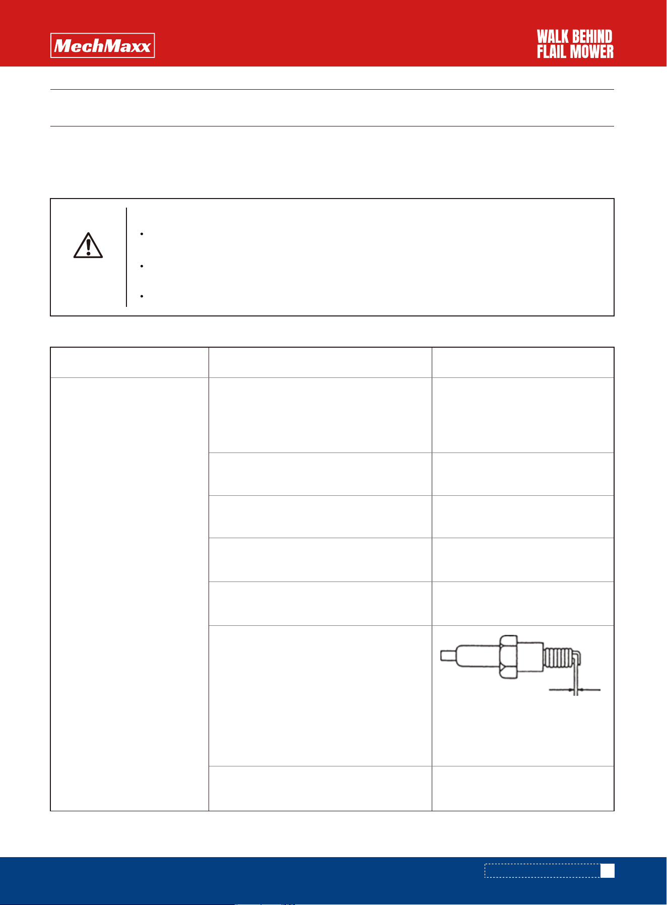
Remove the spark plug s leeve and remove the spark
plug with the attached box wrench. Remove the
carbon deposit on the spa r k plug and adjus t the
electrode gap to "0.02 ~ 0.03 inch".
When the electrode part is worn or damaged, please
replace it with a new spark plug.
After installing the spark plug, make sure that the
spark plug cap is inserted.
Using spark plugs......... NGK bpr6es Denso w20epr u
Please do not pull the starting pull plate with the
spark plug cover removed.
The spark plug is not connected to the grounding on
the engine side. Please do not pull the starting pull
plate. Can cause engine circuit failure. Please check
the grounding.
If the engine cannot be started even if the electrode
gap of the spark plug is adjusted, please replace it
with a new spark plug.
Check whether there is water or garbage in the cup.
Turn the fuel switch to off, remove the cup, wash it
with lamp oil and install it.
Inside the air filterPolyurethane foam
Fuel switch handle
glass
Close
0.02~0.03 inch
MAINTENANCE METHOD
INSPECTION AND ADJUSTMENT OF EACH
PART
26
www.mechmaxx.com
5. Inspection of protective cover
1. Adjustment of traveling clutch stay wire
To prevent injury accidents
If the protective cover is cracked,
deformed or shortened, there will
be more foreign matters such as
stones flying out, because it is
very dangerous, please replace it in
time.
WARNING
To prevent injury accidents
Clean, check and adjust the
machine in a flat place until all
parts stop running.
After adjustment, try whether the
machine is abnormal.
WARNING
To prevent injury accidents
Stop the engine and then adjust
the travel clutch.
After starting the engine and
confirming that the belt is not
rotating, shift the gear lever into
"n" gear. Don't get close to people
or objects. Don't get close to the
engine pulley or belt with your
hands and feet.
Ins tall the belt cover after adjust-
ment.
Please don't adjust the belt too
tight. If the belt is too tight, the
walking clutch rod cannot be
disconnected, which may cause
accidents.
WARNING
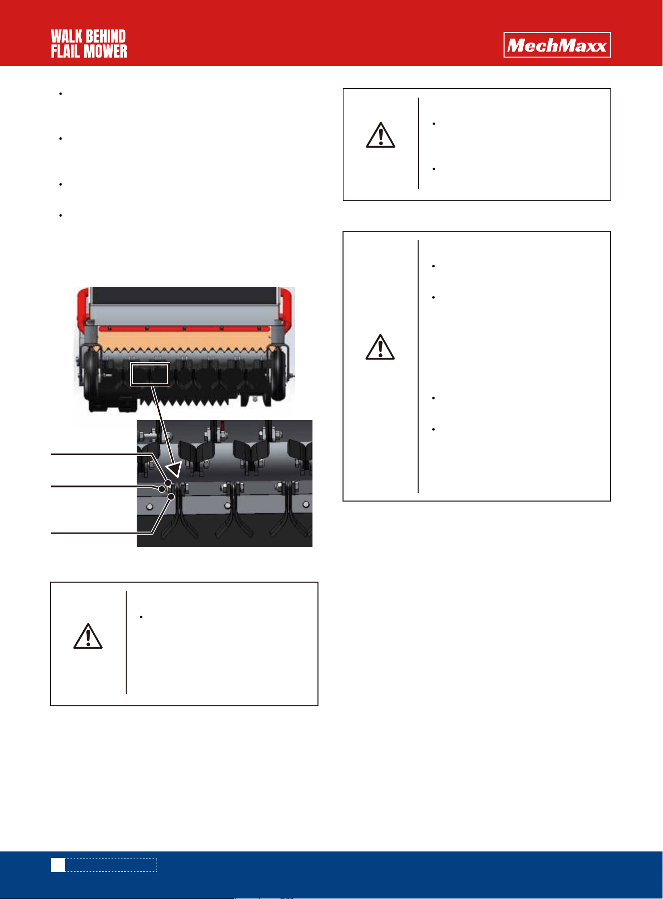
All pa rt s ha ve be en prope rly debugged before leaving
the factory, but due to wear and tension during use, they
should be debugged and replaced with parts exceeding
the loss limit to make them in a state of normal use.
If the corner of the cutter is seriously worn, it is
necessary to change the cutter to a new side and cut
the grass with a new side
The cutting knife (38 pieces in total) is fixed on the
connecting accessories (19 places in total) with
bolts on the back of each two pieces.
Screw in the flat direction of the fastening nut
towards the bolt.
After tightening the bolt and fastening nut with tools,
the bolt protrudes more than 2 threads from the end
face of the fastening nut. Please make sure that the
two cutters can rotate freely in the cutter connecting
accessories.
The traveling clutch rod is belt tensioned, and the travel-
ing clutch is not adjusted well. If it is too loose, it will lead
to low operation efficiency and performance, and acceler-
ate the wear of V-belt.
In addition, the belt is too tight, the travel clutch rod
cannot be disconnected, and the machine will not stop.
Fastening nut
Take and
change tools
Bolt
MAINTENANCE METHOD
HANDLING IN CASE OF FAILURE
27
www.mechmaxx.com
1.Engine part
To prevent injury accidents
In case of failure during work, please stop the machine in a spacious and flat place, turn off the
engine, and wait until all parts stop working.
The inspection and ser vicing around the engine shall be carried out after the engine has cooled
down.
Please install all the removed panels before starting the engine.
WARNING
Once a fault occurs, find out the cause immediately and deal with it to prevent the expansion of the fault.
If you don't know the reason or it happens again after adjustment, please consult the "buyer" for inspection.
At that time, please summarize the fault, "model name" and "machine number" to the buyer.
Fault condition
1. the engine cannot be
started.
(1) wrong operation. No damper handle.
(2) there is no oil in the oil tank.
Replenish fuel and put the
fuel switch on
Clean the air filter element
and replace it if it is dirty.
Remove the cover and clean it.
Remove the spark plug and allow it
to dry sufficiently.
Adjust the electrode gap of the
ignition plug.Clean the carbon
deposit on the spark plug.Replace
the spark plug with a new one.
Rotate the control lever slightly
to the "high" side.
(3) the air filter element is blocked by
garbage
(4) there is water or garbage mixed in the
cover
(5) the spark plug is damp. Excessive
damper, etc
(6) the spark plug does not ignite or the
ignition is relatively weak.
(7) is the position of the engine control
lever good?
set the engine switch to the " i n "
position. Start the operation in the
correct order.when the engine is
cold, pull the damper handle and
start it again.
Cause (inspection site)
Handle
0.02~0.03 inch
HANDLING IN CASE OF FAILURE

28
www.mechmaxx.com
Fault condition
2. insufficient engine output
Automatic engine shutdown
The engine won't stop
There is water or garbage mixed in the lid.
There is rubbish in the air filter element.
Clean the air filter element and
replace it if it is dirty.
Clean up.
Replenish the oil to the specified
amount.
If it's dirty, change the standard oil.
Adjust all parts properly to avoid
overload operation
Considering the wear of piston ring
and other problems, consult with
the "buyer”
Check the looseness of engine
control lever, cable assembly and
mounting part
The air inlet of the starting handle is
blocked.
Insufficient and poor engine oil.
Overload operation
No engine compression pressure
Insufficient engine operation
The damper handle is in the "closed"
position
Mud or grass is blocked in the cutter cover.
The wiring end of the engine stop switch
falls off.
Adjust the damper handle to
the "open" position
Clean up the grass and mud, and
clean up the sundries (iron wire,
plastic, etc.) wound on the
cutting knife.
Connection port.
Read the engine manual.
Remove the cover and clean it.
Cause (inspection site)
Handle
HANDLING IN CASE OF FAILURE

29
www.mechmaxx.com
2. Local part
Fault condition
The straightness is poor and
the track falls off.
The travel clutch cannot be
cut off (does not stop).
Even if the driving clutch is
put in, it will not start.
Poor rotation performance.
The steering clutch cannot be
cut off.
The parking brake does not
work.
The cutter clutch cannot be
cut off (does not stop).
The clutch does not rotate
even if the cutter is put in.
Residues from mowing.
The vibration of the machine
is greater than when it was
purchased.
The tension on the left and right sides of the
track is different.
The track is loose.
The belt is too tight.
Belt slipping. The belt is worn.
The steering clutch lever is loose.
The length of the parking brake spring is
poor.
The belt is too tight. The length of the cutter
brake spring is poor
Belt slipping. The belt is worn.
Wear of cutter.
The cutter is bent. Hard mowing.
The cutter is very worn. Replace all cutting
knives with new ones. The new cutter is
installed with the old cutter. The cutter fell
off.
Something's wrapped around the knife.
Adjust the left and right tracks to
the specified tension.
Adjust the travel clutch cable.
Replace the belt with a new one.
Adjust the travel clutch lever to
"cut" and adjust the cable.
Adjust the cutter clutch cable.
Adjust the cutter clutch lever to
the "cutting" position and adjust
the cable.
Adjust the cutter clutch cable.
Replace the belt with a new one.
Install the cutter on another side.
Replace all cutting knives with
new ones.
Install a new cutter. Get rid of
what's wrapped in the knife
Adjust the steering clutch lever.
Adjust the travel clutch cable.
Cause (inspection site)
Handle
HANDLING IN CASE OF FAILURE
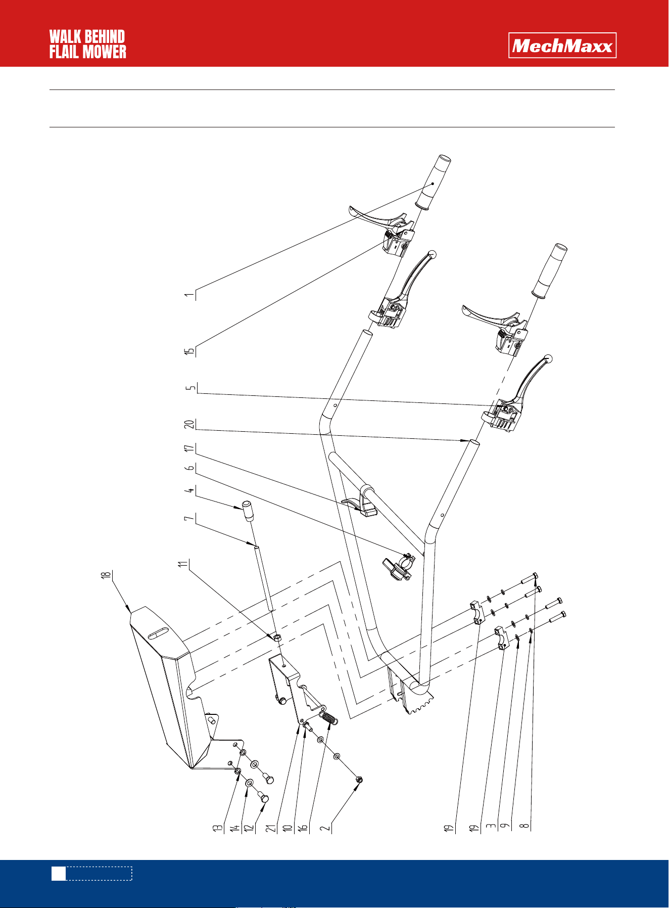
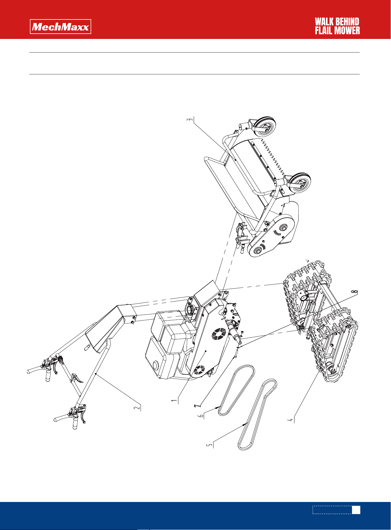
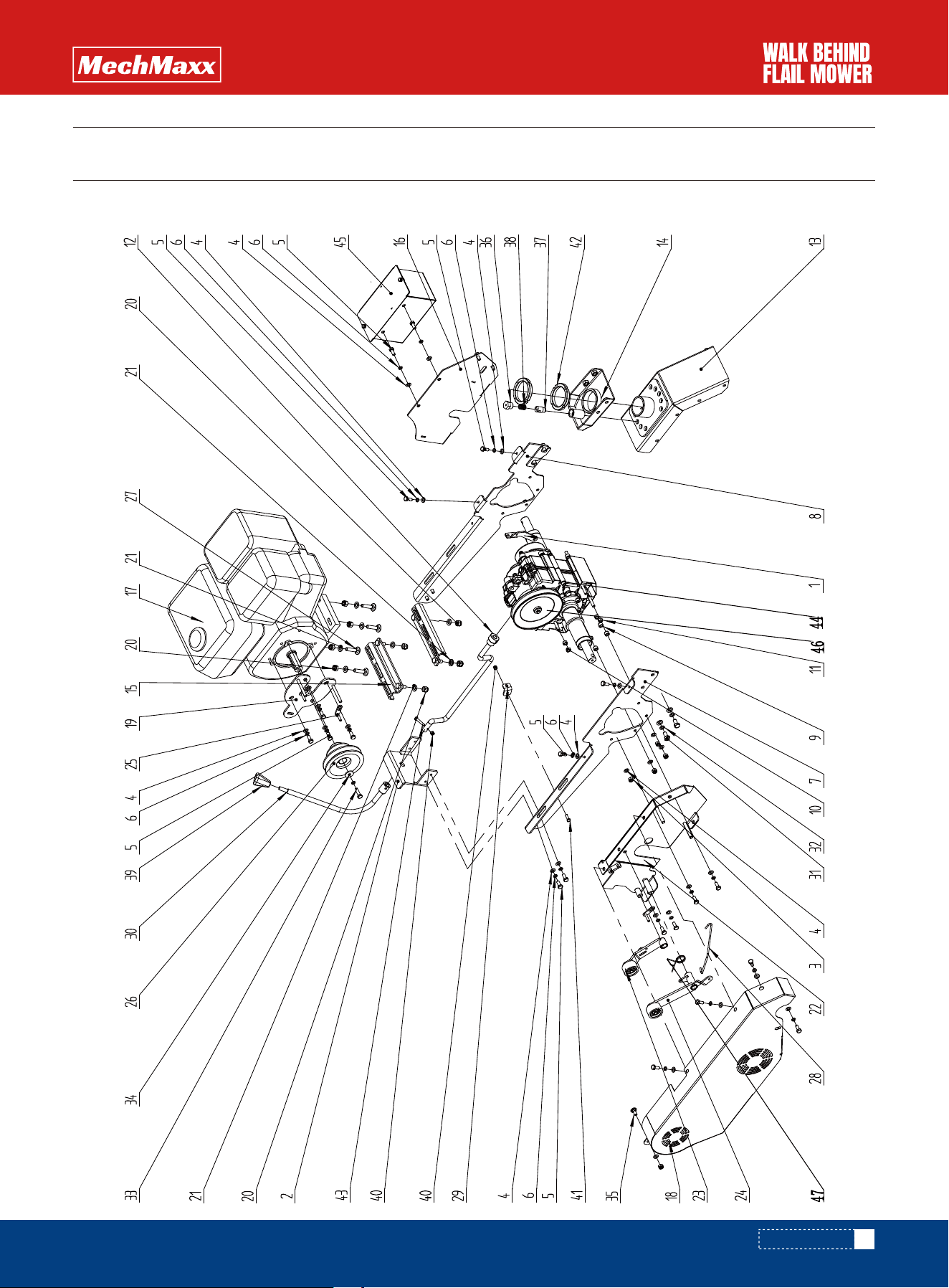
PARTS DIAGRAM
30
www.mechmaxx.com
SFM27W
PARTS DIAGRAM

1
1
1
2
1
1
2
10
2
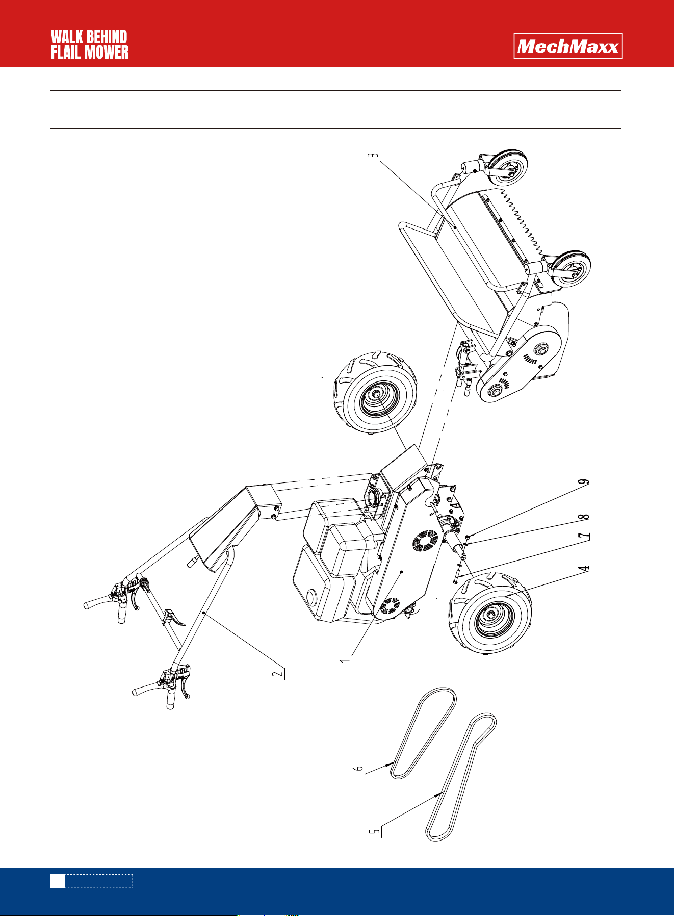
No. QtyCode Description Specification
1
2
3
4
5
6
7
8
9
HTC666,30.000
HTC666,10.001
HTC666,60.000
G35783-2000
GB9-2002
GB869.1-2000
Engine and gearbox part
Handle assembly
Bladebox assembly
Left and right tires 15X5-6
V-belt 2
V-belt 1
Hexagonal bolt
Flat washer
Hexagonal lock nut
SB62
1145
M10*55
10
M10
PARTS LIST
31
www.mechmaxx.com
PARTS LIST
32
www.mechmaxx.com
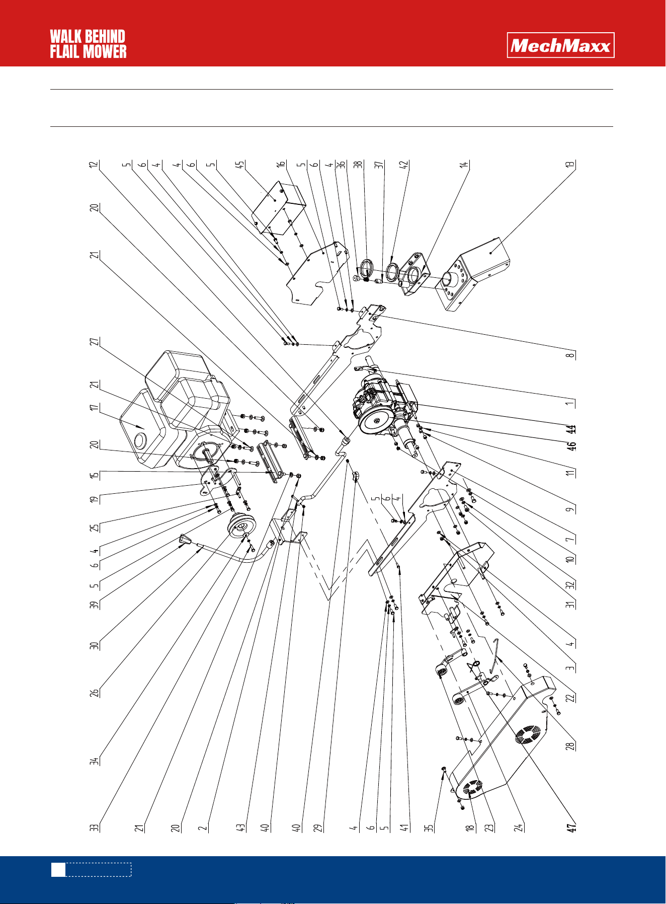
PARTS DIAGRAM
SFM27W
PARTS DIAGRAM

2
2
8
1
2
1
1
4
4
2
1
4
4
4
2
1
1
1
2
1
1
No. QtyCode Description Specification
1
2
3
4
5
6
7
8
9
10
11
12
13
14
15
16
17
18
19
20
21
0301A.10.103
GB/T889.1-2000
6B/T 95-2002
0302B.10.122
0301C.10.001
0301A.00.130
GB/T 5783-2000
GB/T 93-1987
GB/T5783-2000
GB/T 6170-2000
GB/T 5783-2016
GB/T 93-1987
GB/T 95-2002
0301A.10.001
Brake handle 1
HTC666.10.035
HTC666.10.122
HTC666.10.050
HTC666.10.034
Grip 25
Metal inlaid locking nut
Flat washer Class C
High and low gear grip
Lower handle assembly
Throttle assembly
Height adjustment handle
Hexagon head bolt Full thread
Standard elastic washer (assembly)
Hexagon head bolt Full thread
Type 1 hexagonal nuts, grade A and B,
Hexagonal head bolts, full smoke pattern,
Standard strong washers (assembly)
Flat washers, grade C 10
Upper handle assembly
Platform tension spring
Brake handle
Handle front cover welding
Handle pressure block
Handle welding
Limit rod welding
M8
8
10
M8X 40
8
M8X25
M10
M10X25
10
10
4X22X100
T12
PARTS LIST
33
www.mechmaxx.com
PARTS LIST
34
www.mechmaxx.com
PARTS DIAGRAM
PARTS DIAGRAM
SFM27W

1
1
9
34
25
26
1
1
6
2
8
1
1
1
2
1
1
1
1
8
12
1
1
1
3
1
4
1
1
1
4
4
No. QtyCode Description Specification
1
2
3
4
5
6
7
8
9
10
11
12
13
14
15
16
17
18
19
20
21
22
23
24
25
26
27
28
29
30
31
32
HTC666.37.203
HTC6660.30.023
GB/T 889.1-2000
GB/T 95-2002
GB/T 5781-2000
GB/T 93-1987
HTC666.30.010
HTC666.30.010L
HTC666.37.102
HTC666.37.103
GB/T 6170-2000
HTC666.37.010
HTC666.20.010
HTC666,10.040
HTC666.30.050
HTC666,20.040
HTC666.00.010
HTC666.20.050
GB/T889.1-2000
GB/T 95-2002
HTC666. 20.030ll
HTC666.60.081-000
BTC666,60.080-000
HTC666,20.060
HTC666.00.106 1
GB/T 14-1988
HTC666. 60.146
HTC666.20.111
HTC666.37.020
GB/T 5783-2000
GB/T 93-1987
Brake pull plate
Frame rear plate
Non-metallic hexagonal lock nut
Flat washer
Hexagonal bolt
Standard spring washer
Frame right side plate welding
Frame left side plate welding
Frame spacer 1
Frame spacer 2
Hexagonal nut
Shift lever welding
Lower turntable welding
Upper turntable welding
Engine mounting base welding
Turntable lower support plate welding
Engine
Belt nut welding
Belt nut fixing plate welding
Non-metallic hexagonal locking nut
Flat washer
Belt cover inner plate
Travel clutch pull plate assembly
Fling knife tensioner assembly
Belt shaft welding
Double groove reducing AB pulley
Large semicircular head square neck bolt
Brake rod Hot rolled spring steel
Cable swivel fixing plate T4
Shift handle welding
Hexagon head bolt
Standard spring washer 10
Q235
Q235
M8
8
M8*20
8
Welding
Welding
Q235
Q235
M8
M10
10
Q235
M10x45
M10x20
PARTS LIST
35
www.mechmaxx.com
PARTS LIST

1
1
1
1
1
1
1
2
1
2
1
1
1
1
1
No. QtyCode Description Specification
33
34
35
36
37
38
39
40
41
42
43
44
45
46
47
GB/T 5783-2000
GB/T 5287-2002
GB/T 794-93
0301A.00.130
GB/T889.1-2000
GB/T5783-2000
GB/T 810-1988
GB/T 5783-2000
HTC666.37.000
HTC666.50.020.00
HTC666.37.
HTC666.60.1161
Hexagon bolt
Extra large washer
Strengthened semicircular head square neck newt bol
Screw plug cover
Locating pin
Locating pin spring
Handle
Non-metallic hexagonal locking nut
Hexagon head bolt
Small round nut
Hexagon head bolt
Transformer box assembly
Battery box assembly (external)
104 Large pulley
Brake torsion spring (short) 65Mn/Ф2
M8×30
8X3
M8x25
M6
M6x20
M64x2
M6x35
Q235
36
www.mechmaxx.com
PARTS LIST
37
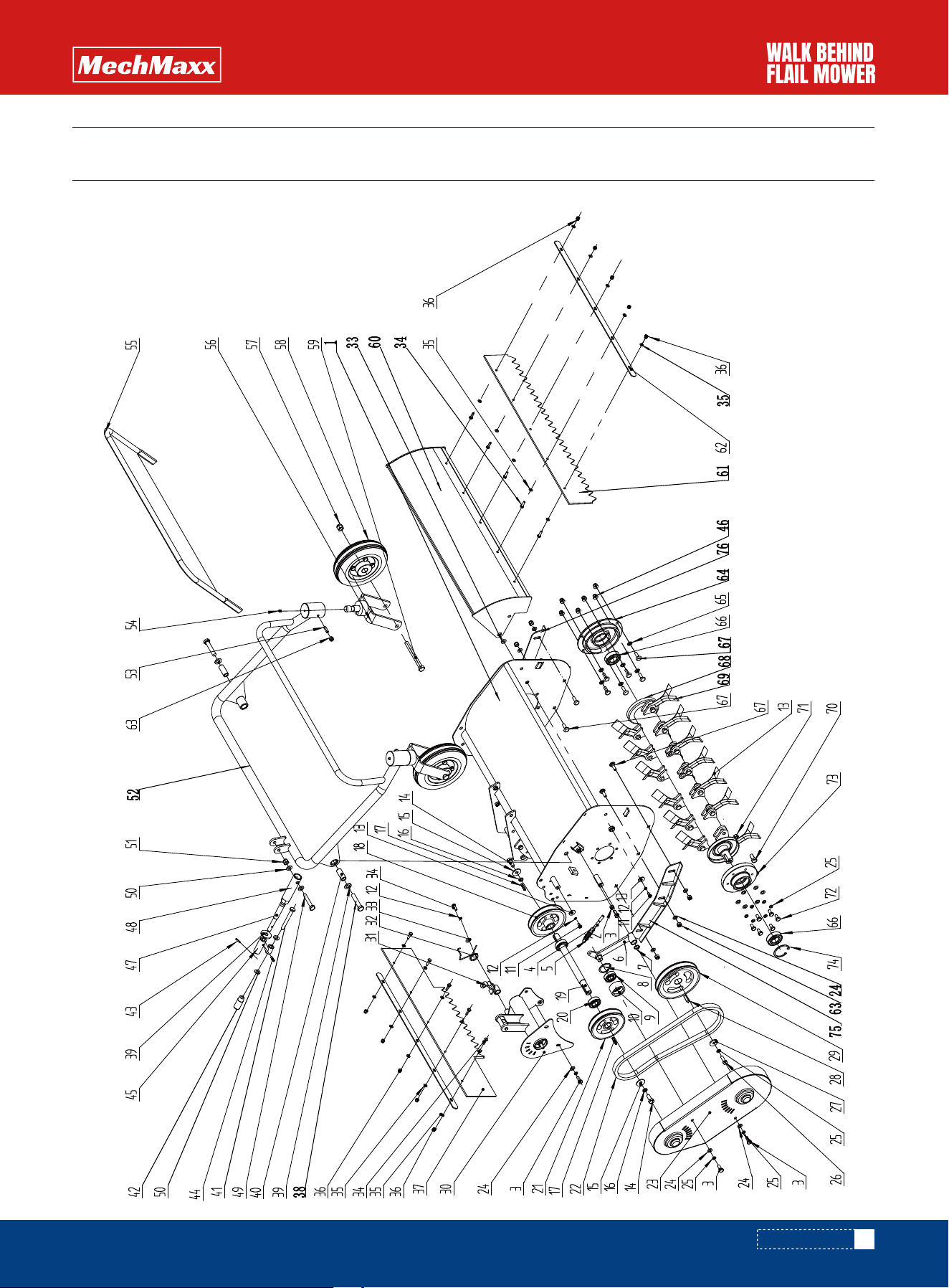
www.mechmaxx.com
PARTS DIAGRAM
PARTS DIAGRAM
SFM27W

38
www.mechmaxx.com
PARTS LIST
1
2
7
1
1
1
1
1
1
1
3
4
1
2
2
2
2
1
1
2
1
1
18
14
1
1
1
1
1
1
1
3
No. QtyCode Description Specification
1
2
3
4
5
6
7
8
9
10
11
12
13
14
15
16
17
18
19
20
21
23
24
25
26
27
28
29
30
31
32
33
HTC666.60.020
GB/T6170-2000
GB/T5781-2000
GB/T 798-1988
HTC666.60.110
GB/T 894-2017
GB/T 893-2017
GB/T 276-2013
HTC666.60.115
GB/T 5783-2000
GB/T 93-1987
GB/T5287-2002
GB/T5783-2000
GB/T5287-2002
GB/T 93-1987
GB/T 1096-2003
HTC666.60.082
HTC666.60.059
GB/T 276-2013
HTC666.60.082-2
HTC666.60.090
GB/T 95-2002
GB/T93-1987
GB/T 5783-2000
GB/T 5287-2002
GB/T1096-2003
HTC666.60.083
HTC666.60.070
HTC666.60.084
HTC666.60.116A
GB/T 96.2-2002
Welding of tool box
Type 1 hexagonal nut Grade A and Grade В
Hexagonal head bolt full thread Grade C
Visor bolt
Platform tension spring
Transmission tension welding
Circlip for shaft A type
Circlip for hole A type
Deep groove ball bearing 6203-2Z
Transmission tensioner
Hexagon head bolt Full thread
Standard elastic washer (assembly)
Extra large washer Class C
Hexagon head bolt Full thread
Large washer Class A 10
Standard elastic washer
Ordinary flat key C type
Power transmission pulley-1
Drive shaft
Deep groove ball bearing 6004-2RS
Drive pulley-2
Knife box belt welding
Flat washer grade 8X1.6
Standard elastic washer (assembly)
Hexagon head bolt Full thread
Extra large washer C grade
Ordinary flat key C type
Knife shaft pulley
Drive shaft welding
Brake plate assembly
Brake torsion spring (long)
Large washer grade
M8
M8X20
M8X60
4X22X62 65Mn/ø4
16
40
6203-22
Q235
M6X12
6X1.6
6X2
M10X25
10X3
10×2.6
5x28
Q235
Q235
6004-2RS
Q235
8X2.1
M8X25
8X3
8X25
Q235
Φ65Mn/2.5
6X1.6
PARTS LIST

39
www.mechmaxx.com
PARTS LIST
11
20
10
1
2
7
2
1
1
1
1
1
6
1
1
1
4
1
1
2
2
1
2
2
2
2
1
1
2
8
1
6
2
12
No. QtyCode Description Specification
34
35
36
37
38
39
40
41
42
43
44
45
46
47
48
49
50
51
52
53
54
55
56
57
58
59
60
61
62
63
64
65
66
67
GB/T5783-2000
GB/T 95-2002
GB/T 889.1-2000
HTC666.60.144
GB/T5782-2016
GB/T 96.2-2002
HTC666.60.047
GB/T882-2008
0302B.10.122
GB/T 879.1-2000
GB/T 879.1-2000
HTC666.60.140
GB6187-2000
HTC666.60.132L
HTC666.60.130
GB/T 5782-2000
GB/T 95-2002
GB/T 889.1-2000
HTC666.60.040
GB/T 79-2000
1-1995 Straight-through oil cup M6 Stand
HTC666.60.060
HTC666.60.100
GB/T 889.1-2000
HTC666.60.085
GB/T 5782-2000
HTC666.60.010
HTC666.60.145
HTC666.60.014
GB/T 889.1-2000
HTC666.60.117
HTC666.60.147
GB/I 276-94
GB/T 794-93
Hexagon head bolt Full thread
Flat washer grade C
Type 1 non-metallic insert hexagonal lock nut
Rubber rear baffle Industrial rubber
Hexagonal bolt M12X60
Flat washer Class C 12
Sleeve Q235
Pin A type 10X85
High and low gear handle
Elastic cylindrical pin/straight slot
Elastic cylindrical pin/ straight slot
Adjustment handle
All-metal hexagonal flange lock nut
Height adjustment rod (long)
Height adjustment
Hexagon head bolt, grade A and grade B
Flat washer, grade C
Type 1 non-metallic insert hexagonal lock nut
Adjustment tube welding
Hexagon socket cylindrical end set screw
Straight-through oil cup
Bevel baffle welding
Wheel frame welding
Type 1 non-metallic insert hexagonal lock nut
Tire assembly
Hexagonal bolts Grade A and B
Front cover welding
Rubber front baffle Industrial rubber
Rubber strip T3
Feng metal inlaid locking nut
Bearing cover
Square neck bolt washer
Deep groove ball bearing
Reinforced semicircular head square neck bolt
M6X20
6X1.6
M6
M12X60
12
10×85
3X20
5X20
M8
Q235
M10X60
10X2
M10
M8X25
M6
M12
M12×120
M8
Q235
Q235/T1.5
6205-2RZ
M8X25

40
www.mechmaxx.com
PARTS LIST
1
38
19
19
Cutter shaft welding
Hob 65MCH
Hexagon head bolt
62-type full metal hexagon lock nut
No. QtyCode Description Specification
68
69
70
71
HTC666.60.050-3
HTC666.60.064
GB/T 5782-2016
GB/T6185.1-201
M10X35
M10
41
www.mechmaxx.com
PARTS DIAGRAM
PARTS DIAGRAM
SFM27T

1
1
1
1
1
1
2
4
No. QtyCode Description Specification
1
2
3
4
5
6
7
8
HTC666.30.000
HTC66610.001A
HTC860.60.000
HTC666.40.000
GB70.1-2000
GB95-2002
Engine and gearbox
Handrail assembly
Tool box assembly
Wheel frame assembly
V-belt 2
V-belt
Hexagon socket head screw
Flat washer
SB62
SB44
M10x55
10
PARTS LIST
42
www.mechmaxx.com
PARTS LIST
43
www.mechmaxx.com
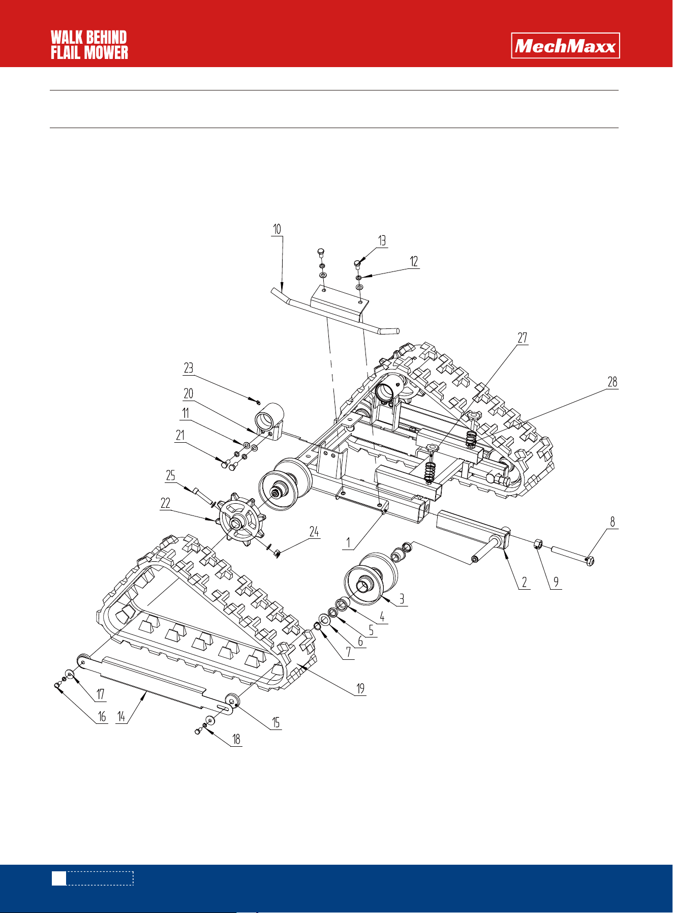
PARTS DIAGRAM
PARTS DIAGRAM
SFM27T

1
1
9
34
25
26
1
1
6
2
8
1
1
1
2
1
1
1
1
8
12
1
1
1
3
1
4
4
1
1
1
4
No. QtyCode Description Specification
1
2
3
4
5
6
7
8
9
10
11
12
13
14
15
16
17
18
19
20
21
22
23
24
25
26
27
28
29
30
31
32
HTC666.37.203
HTC6660.30.023
GB/T889.1-2000
GB/T 95-2002
GB/T 5781-2000
GB/T 93-1987
BTC666.30.010
BTC666.30.010L
HTC666.37.102
HTC666.37.103
GB/T6170-2000
HTC666.37.010
HTC666.20.010
HTC666.10.040
BTC666.30.050
HTC666.20.040
HTC666.00.010
HTC666.20.050
GB/T 889.1-2000
GB/T 95-2002
HTC66620.030Il
HTC666.60.081-000
HTC666.60.080-000
HTC666.20.060
HTC666.00.105
GB/T 14-1988
GB/T 14-1988
HTC666.60.146
HTC666.20.111
HTC666.37.020
GB/T 5783-2000
Brake pull plate
Frame rear plate
Feng Metal Hexagon Lock Nut
Flat Washer
Hexagon Head Bolt
Standard Spring Washer
Frame right side plate welding
Frame left side plate welding
Frame spacer 1
Frame spacer 2
Hexagonal nut
Shift lever welding
Lower turntable welding
Upper turntable welding
Engine mounting base welding
Turntable lower support plate welding
Engine
Belt cover welding
Belt nut fixing plate welding
Feng Metal Hexagonal Locking Nut
Flat washer
Belt inner plate welding
Walking clutch pull plate assembly
Fling knife tensioner assembly
Belt shaft welding
Double groove reducing BB pulley
Half turn head square neck bolt
Half-turn square neck bolt
Brake rod Hot-rolled spring
Cable rotation fixing plate
Shift handle welding
Hexagonal bolt
Q235
Q235
M8
8
M8x20
8
Q235
Q235
M8
M10
10
Q235
M10x45
M10x45
T4
M10*20
PARTS LIST
44
www.mechmaxx.com
PARTS LIST

4
1
1
1
1
1
1
1
2
1
2
1
1
1
1
1
No. QtyCode Description Specification
33
34
35
36
37
38
39
40
41
42
43
44
45
46
47
48
GB/T 93-1987
GB/T 5783-2000
GB/T 5287-2002
GB/T 794-93
0301A.00.130
GB/T 889.1-2000
GB/T 5783-2000
GB/T 810-1988
GB/T 5783-2000
HTC666.37.000
HTC666.50.020.00
0301A.37.028
HTC666.60.116
Standard spring tube washer
Hexagon bolt
Extra large washer
Strengthened semicircular head square neck bolt
Screw plug cap
Locating pin
Locating pin spring
Handle
Non-metallic hexagonal locking nut
Hexagon head bolt
Small round nut
Hexagon head bolt
Transmission box assembly
Battery box assembly (external)
PE wheel
Brake torsion spring
10
M8x30
8X3
M8x25
M6
M6*120
M64x2
M6x35
65mn/Φ2
45
www.mechmaxx.com
PARTS LIST
46
www.mechmaxx.com
PARTS DIAGRAM
SFM27T
PARTS DIAGRAM

1
2
4
8
8
4
4
2
2
2
12
8
4
2
2
4
4
4
2
2
4
2
2
2
2
2
2
No. QtyCode Description Specification
1
2
3
4
5
6
7
8
9
10
11
12
13
14
15
16
17
18
19
20
21
22
23
24
25
27
28
HTC666.40.050
HTC666,40.040
0302C.30.060
0302B.30.412
GB/T 13871.1-2007
GB/T 95-2002
GB/T 894-2017
GB/T 5783-2000
GB/T 6170-2000
HTC666.40.020
GB/T 95-2002
GB/T 93-1987
GB/T5783-2000
HTC666.40.010
0302C.30.408
GB/T 5781-2000
GB/T 5287-2002
GB/T 93-1987
HTC666.30.040
GB /T 5783-2016
0301A.37.146
JB/T 7940.1-1995
GB/T 889.1-2000
GB/T 70.1-2000
JEF XL.00.103
0301A.20.301
Wheel frame welding
Slideway wheel frame welding
Small roller welding
Roller wear sleeve
Rotating lip seal
Flat washer Class C
Elastic retaining ring for shaft A type
Hexagon head bolt Full thread
Type 1 hexagon nut Grade A and Grade B
Roller guard welded
Flat washer Grade C
Standard elastic washer (assembly)
Hexagonal head bolt Full thread
Axle guard welded
Roller dust cover
Hexagonal head bolt Full thread Grade C
Extra large washers Class C
Standard elastic washers (assembly)
Track-180*25*60
Transmission support sleeve welding
Hexagonal bolt Full thread
Driving wheel
Straight-through pressure injection oil cup
Type 1 non-metallic insert hexagonal lock nut
Hexagon socket head screw
Star bolt
Retraction spring
20*28*8
20
20
M16X120
M16
10
10
M10X20
Q235/T2
M8X20
8X3
8
25 sections
M10X25
6
M10
M10X55
M8X40
PARTS LIST
47
www.mechmaxx.com
PARTS LIST
48
www.mechmaxx.com
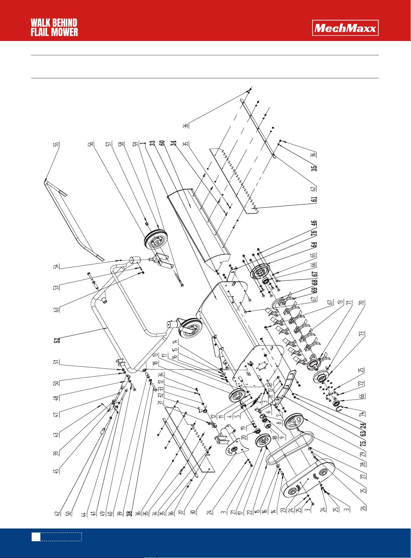
PARTS DIAGRAM
SFM27T
PARTS DIAGRAM

49
www.mechmaxx.com
PARTS LIST
1
2
7
1
1
1
1
1
1
1
3
4
1
2
2
2
2
1
1
2
1
1
1
18
14
1
1
1
1
1
1
1
No. QtyCode Description Specification
1
2
3
4
5
6
7
8
9
10
11
12
13
14
15
16
17
18
19
20
21
22
23
24
25
26
27
28
29
30
31
32
HTC666.60.020
GB/T 6170-2000
GB/T 5781-2000
GB/T 798-1988
HTC666.60.110
GB/T 894-2017
GB/T 893-2017
GB/T 276-2013
HTC666.60.115
GB/T 5783-2000
GB/T 93-1987
GB/T 5287-2002
GB/T 5783-2000
GB/T 5287-2002
GB/T93-1987
GB/T 1096-2003
HTC666.60.082
HTC666.60.059
GB/T 276-2013
HTC666,60.082-2
GB/T 1171-2006
HTC666.60.090
GB/T 95-2002
GB/T93-1987
GB/T 5783-2000
GB/T5287-2002
GB/T 1096-2003
HTC666.60.083
HTC666.60.070
HTC666.60.084
HTC666.60.116A
Tool box welding
Type 1 hexagonal nut Grade A and B
Hexagonal head bolt full thread Grade C
Visor bolt
Platform tension spring
Transmission tension welding
Elastic retaining ring for shaft
Elastic retaining ring for hole
Deep groove ball bearing
Transmission tensioner
Hexagon head bolt Full thread
Standard elastic washer (assembly)
Extra large washer Class C
Hexagon head bolt Full thread
Large washer Class A
Standard elastic washer
Ordinary flat key C type
Power transmission pulley-1
Transmission shaft
Deep groove ball bearing 6004-2RS
Transmission pulley-2
V-belt
Knife box belt cover welding
Flat washer grade
Standard elastic washer (assembly)
Hexagon head bolt full thread
Extra large washer C grade
Ordinary flat key C type
Knife shaft pulley
Drive shaft welding
Brake plate assembly
Brake torsion spring (long)
M8X20
M8X60
4X22X62
6203-2Z
Q235
M6X12
6X1.6
6X2
M10X25
10X3
10X2.6
5X28
Q235
Q235
Q235
SB38.5-1000W
8X1.6 S
8X2.1
M8X25
8X3
8X25
Q235
PARTS LIST

50
www.mechmaxx.com
PARTS LIST
3
11
20
10
1
2
7
2
1
1
1
1
1
6
1
1
1
4
1
1
2
2
1
2
2
2
2
1
1
2
8
1
6
2
No. QtyCode Description Specification
33
34
35
36
37
38
39
40
41
42
43
44
45
46
47
48
49
50
51
52
53
54
55
56
57
58
59
60
61
62
63
64
65
66
GB/T 96.2-2002
GB/T 5783-2000
GB/T 95-2002
GB/T 889.1-2000
HTC666.60.144
GB/T 5782-2016
GB/T 96.2-2002
HTC666.60.047
GB/T 882-2008
0302B.10.122
GB/T 879.1-2000
GB/T 879.1-2000
HTC666.60.140
GB6187-2000
HTC666.60.132
HTC666.60.130
GB/T 5782-2000
GB/T 95-2002
GB/T 889.1-2000
HTC666.60.040
GB/T 79-2000
JB/T7940.1-1995
HTC666.60.060
HTC666.60.100
GB/T 889.1-2000
HTC666.60.085
GB/T 5782-2000
HTC666.60.010
HTC666.60.145
HTC666.60.014
GB/T 889.1-2000
HTC666.60.117
HTC666.60.147
GB/T 276-94
Large washer Grade
Hexagon head bolt Full thread
Flat washer Grade C
Type 1 non-metallic insert hexagonal lock nut
Rubber rear baffle Industrial rubber
Hexagon head bolt
Flat washer C grade 12
Sleeve
Pin A type 10X90
High and low gear handle
Elastic cylindrical pin straight slot
Elastic cylindrical pin straight slot
Adjustment handle welding
All-metal hexagonal flange lock nut
Height adjustment rod (short)
Height adjustment welding
Hexagon head bolt grade A and grade B
Flat washer grade C
Type 1 non-metallic insert hexagonal lock nut
Adjustment tube welding
Hexagon socket cylindrical end set screw
Straight oil cup
Bevel baffle welding
Wheel frame welding
Type 1 non-metallic insert hexagonal lock nut
Tire assembly
Hexagon head bolts Grade A and B
Front cover welding
Rubber front baffle Industrial rubber
Rubber strip T3
Non-metallic inlaid locking nut
Bearing cover
Square neck bolt washer
Deep groove ball bearing
6X1.6
M6X20
6X1.6
M6
M12X60
12
Q235
10X90
3X20
5×20
M8
Q235
M10X60
10X2
M10
M8X25
M6
M12
M12X120
M8
Q235
Q235/T1.5

51
www.mechmaxx.com
12
1
37
19
19
8
1
1
1
1
Strengthened semicircular head square neck bolt
Knife shaft welding
Rotating knife
Hexagon bolt
62-type all-metal hexagon lock nut
Hexagon bolt Full thread
Bearing seat
Circlip for hole A type
Right slide plate welding
Left slide plate welding
No. QtyCode Description Specification
67
68
69
70
71
72
73
74
75
76
GB/T 794-93
HTC666.60.050-3
HTC666.60.064
GB/T 5782-2016
GB/T 6185.1-201
HTC666.60.058
GB 893.1-86
GB/T 5783-2000
HTC666.60.155
HTC666.60.159
M8X25
M10X35
M10
M8 X16
Q235
PARTS LIST