Operator’s Manual
www.mechmaxx.com
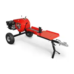
Model: KT34
WARRANTY


TABLE OF CONTENTS
TABLE OF CONTENTS
SPECIFICATIONS
SAFETY SIGNS
SAFETY
1
2
7
4
5
13
MAINTENANCE
14
TROUBLESHOOTING
16
17
PARTS LISTCONTENTS SUPPLIED
8
ASSEMBLY
10
KNOW YOUR MACHINE
11
OPERATING INSTRUCTIONS
1
www.mechmaxx.com
TABLE OF CONTENTS
PARTS DIAGRAM
INTRODUCTION
Do not start or operate the machine before
you read this manual. Make sure that you
fully understand all the safety, operation,
and maintenance information before you
operate the machine.
Keep this manual with the machine at all
times and available for frequent reference.
This manual provides all the information you need to
operate and maintain your machine safely and effectively.
Read and understand the entire manual before use. If you
have questions that are not addressed here, contact
MechMaxx Customer Support for assistance.
This machine is designed for specific applications only.
We strongly recommend not modifying or using it for any
purpose other than its intended use. If you have questions
about a specific application, DO NOT operate the machine
until you contact us first to confirm it is suitable for that
use.
The engine manufacturer is responsible for all issues
related to engine performance, power rating, specifica-
tions, warranty, and service. Consult the engine manufac-
turer’s owner/operator manual for details.
Record the model and serial number as well as date and
place of purchase for future reference. Have this informa-
tion available when ordering parts or optional accessories
and when making technical or warranty inquiries.
This manual is subject to change without notice. For the
most current information, go to mechmaxx.com.
For available accessories, go to mechmaxx.com.
ENGINE MANUAL
MODEL AND SERIAL NUMBERS

SPECIFICATIONS
2
www.mechmaxx.com
SPECIFICATIONS
Engine
Engine Type
Displacement
Belt
Wedge Height
Log Length Capacity
Log Diameter Capacity
Cycle Time
Sprocket Rate
Flywheel Max RPM
Tire
H-beam Height
Wheelbase
Towing
Product Size (L*W*H)
Packing Size (L*W*H)
Weight (N.W./G.W.)
Machine Warranty
Engine Warranty
DUCAR DH212
Single Cylinder, 4 Stroke, Air-Cooled, OHV
212 cc; 7 HP
A1524Li*1pcs
7in
21.5in
28 in
3 seconds(Approximate)
1 : 8
450
19 x 7.0-8 Tubeless
26in
87in
Tow Bar With 2 in Coupler
110*51*47in
68.5*29.5*27.5in
545/595 lbs
1 Year
1 Year
KT34
3
www.mechmaxx.com
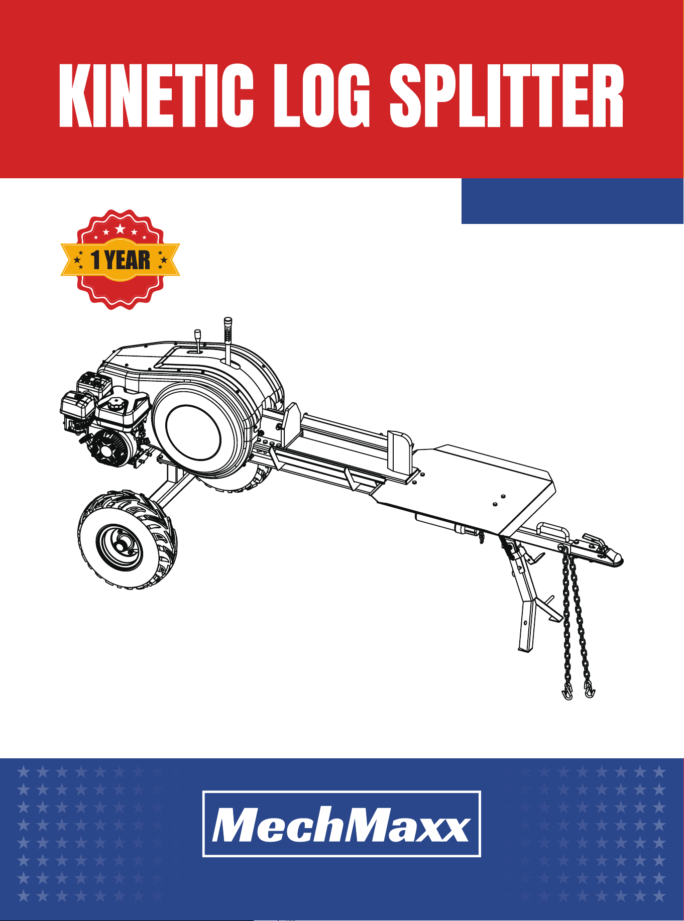
SPECIFICATIONS
596mm
23.4”
1197mm
47.1”
2700mm
106.3”
482mm
18.9”
684mm
26.9”
1250mm
49.2”
666mm
26.2”
489mm
19.2”

4
www.mechmaxx.com
SAFETY SIGNS
SAFETY SIGNS
The LOG SPLITTER carries prominent labels as reminders for its proper and safe use. Copies of all the Safety and Informa-
tion labels that appear on the equipment are shown below. Take a moment to study them and note their location on your
log splitter as you set up and before you operate the unit. Replace damaged or missing safety and information labels
immediately.
Read this Safety & Operating Manual before you use the LOG SPLITTER. And become familiar with
the operation and service recommendations to ensure the best performance of your machine.

5
www.mechmaxx.com
GENERAL SAFETY RULES
SAFETY
SAFETY
Read this manual and the labels affixed to the machine to
understand its limitations and potential hazards. Be
familiar with the controls and their proper operation
thoroughly. Know how to stop the machine and disengage
the controls quickly.
If the unit is to be used by someone other than the original
purchaser or loaned, rented, or sold, always provide this
manual and any needed safety training before operation.
The user is responsible for preventing accidents or
injuries to themselves, other people, and property.
Do not force the machine. Use the correct machine for
your application. The correct machine will do the job more
efficiently and safely at the rate it was designed.
Check your machine before starting. Keep guards properly
installed and functional. Make sure all nuts, bolts, etc.,
are securely tightened.
Never operate the machine when it needs repair or is in
poor mechanical condition. Replace damaged, missing, or
failed parts before use. Check for fuel leaks. Keep the
machine in safe working condition.
Do not use the machine if the engine switch fails to turn
it on or off. Any gasoline - powered machine that cannot
be controlled by the engine switch is dangerous and must
be replaced.
Avoid accidental starting by ensuring the engine switch is
off before transporting the machine or performing any
maintenance or service on the unit. Operating or perform-
ing maintenance on a machine with the switch on can
lead to accidents.
If the machine starts to vibrate abnormally, immediately
stop the engine and check for the cause. Vibration is
generally a warning sign of trouble.
This machine comes equipped with an internal combus-
tion engine. Do not use this machine on or near any unim-
proved, forest - covered, or brush - covered land unless
the exhaust system is equipped with a spark arrester
meeting applicable local, state, or federal laws.
Never start or run the engine inside a closed area as the
exhaust fumes, containing carbon monoxide - an odorless
and deadly gas - are dangerous. Operate this unit only in a
well - ventilated outdoor area.
Do not tamper with the engine in an attempt to make it
run at excessive speeds. The maximum engine speed is
preset by the manufacturer and is within safety limits.
See engine manual.
Keep a Class B fire extinguisher on hand when operating
this log splitter in dry areas for precaution.
At any time, do not permit children to operate this
machine.
Keep children, pets, and other people who are not using
the unit away from the work area. Be alert and shut off the
unit if anyone enters the work area. Keep children under
the watchful care of a responsible adult.
Do not operate the machine while under the influence of
drugs, alcohol, or any medication that could affect your
ability to use it properly.
Dress properly, wear heavy long pants, boots, and gloves.
Do not wear loose clothing, short pants, or jewelry of any
kind. Secure long hair above shoulder level. Keep your hair,
clothing, and gloves away from moving parts. Loose
clothes, jewelry, or long hair can be caught in moving
parts.
Protect your eyes, face, and head from objects that may
be thrown from the unit. Always wear safety goggles or
safety glasses with side shields when operating.
Always keep hands and feet away from all moving parts
during operation, as moving parts can cut or crush body
parts.
Always keep hands and feet away from all pinch points.
Do not touch parts that might be hot from operation.
Allow parts to cool before attempting to maintain, adjust,
or service.
Stay alert, be aware of what you're doing, and use
common sense when operating the machine.
Do not overreach and do not operate the machine while
barefoot or when wearing sandals or similar lightweight
footwear. Wear protective footwear that will protect your
feet and improve your footing on slippery surfaces. Keep
proper footing and balance at all times. This enables
better control of the machine in unexpected situations.
PERSONAL SAFETY
INSPECT YOUR MACHINE
ENGINE SAFETY

6
www.mechmaxx.com
SAFETY
Fuel is highly flammable, and its vapors can explode if
ignited. Take precautions when using fuel to reduce the
risk of serious personal injury.
When refilling or draining the fuel tank, use an approved
fuel storage container in a clean, well - ventilated outdoor
area. Do not smoke, allow sparks, open flames, or other
sources of ignition near the area while adding fuel or
operating the unit, and never fill the fuel tank indoors.
Always stop the engine and allow it to cool before filling
the fuel tank. Never remove the fuel tank cap or add fuel
while the engine is running or hot. Do not operate the
machine with known leaks in the fuel system.
Slowly loosen the fuel tank cap to relieve any pressure in
the tank.
Never overfill the fuel tank. Fill the tank to no more than
1/2" below the bottom of the filler neck to provide space
for expansion.
Replace all fuel tank and container caps securely, wipe up
spilled fuel, and never operate the unit without the fuel
cap securely in place.
If fuel is spilled, avoid creating a source of ignition. Do not
attempt to start the engine; instead, move the machine
away from the spillage area and avoid any source of
ignition until fuel vapors have dissipated.
If fuel spills on you or your clothes, immediately wash your
skin and change your clothes.
Store fuel in containers specifically designed and
approved for storing fuel.
Store fuel in a cool, well - ventilated area, away from
sparks, open flames, or other sources of ignition.
Never store fuel or a machine with fuel in the tank inside
a building where fumes may reach a spark, open flame, or
any other source of ignition, such as a water heater,
furnace, or clothes dryer. Before storing the machine in
any enclosure, allow the engine to cool.
• Always stop the log splitter engine before making any
adjustments, refueling, or cleaning the log splitter.
• Always check that the machine is well supported and
cannot move. If you are working on an incline, position
the log splitter on solid ground across the slope.
• Always visually check for fluid leaks. If found, resolve
the leak before operating the log splitter.
• Always take regular breaks as wearing personal protec-
tive equipment for long periods can be tiring and hot.
• Always keep hands, feet, and clothing away from the
feed opening, discharge area, and moving parts.
• Always keep the operating area clear of people, animals,
and pets.
• Always keep the operating area clear of debris build - up.
• Always ensure the protective guards are in place before
commencing work. Failure to do so may result in
personal injury or loss of life.
• Always operate the log splitter in a well - ventilated
area - exhaust fumes are dangerous.
• Make sure a fire extinguisher is available on site.
• Make sure a personal first aid kit and hand cleaning
materials are available (e.g. waterless skin cleanser).
• Always cover the ignition switch with the provided plug
when towing or jet - wash cleaning.
Some parts of this machine are made of plastic or rubber
and should be kept away from harmful chemicals.
Do not alter or adjust any part of the chipper shredder or
its engine sealed by the manufacturer or distributor. Only
a qualified service technician may adjust parts that
increase or decrease the governed engine speed.
To maintain your machine, check for misalignment or
binding of moving parts. Parts that are broken or worn
down may affect the machine's operation. If damaged or
worn parts are identified, they should be repaired before
use. Many accidents are caused by poorly maintained
equipment.
The list of warnings and cautions cannot be all - inclusive.
If any situations occur that are not covered by this
manual, the operator must apply common sense and
operate this LOG SPLITTER in a safe manner. Contact your
local dealers for assistance in your area.
Never place any part of your body where it would be in
danger if movement should occur during assembly, instal-
lation, operation, maintenance, repair, or moving.
Keep all bystanders and pets at least 75 feet away. If you
are approached, stop the unit immediately.
FUEL SAFETY
OPERATION SAFETY
GENERAL SAFETY MATTERS
MAINTAINING YOUR MACHINE
A NOTE TO ALL USERS
7
www.mechmaxx.com
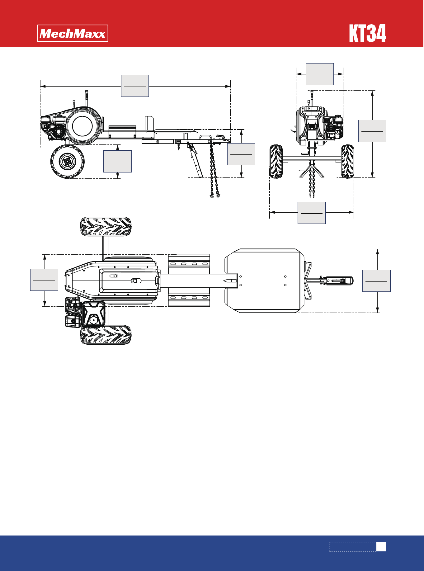
CONTENTS SUPPLIED
CONTENTS SUPPLIED
Your log splitter comes partially assembled and contains the following:
Main frame
1x
1x
1x
Operation handle
Wheel axle
1x
Operation table
Tow bar
1x
2x Wheels
8
www.mechmaxx.com
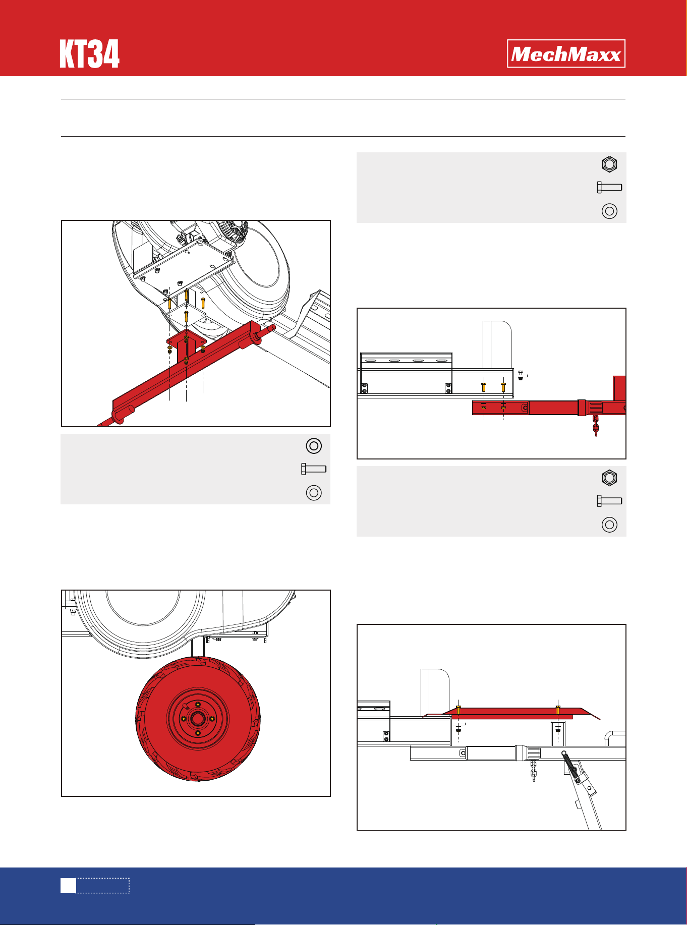
ASSEMBLY
ASSEMBLY
Use full-thread hex head bolts M10×30, flat washers 10,
and M10 hex thin lock nuts to assemble the wheel axle
to the main frame. (See Figure 1)
Use full-thread hex head bolts M10×25, flat washers 10,
and M10 hex thin lock nuts to assemble the wheels onto
the wheel axle. (See Figure 2)
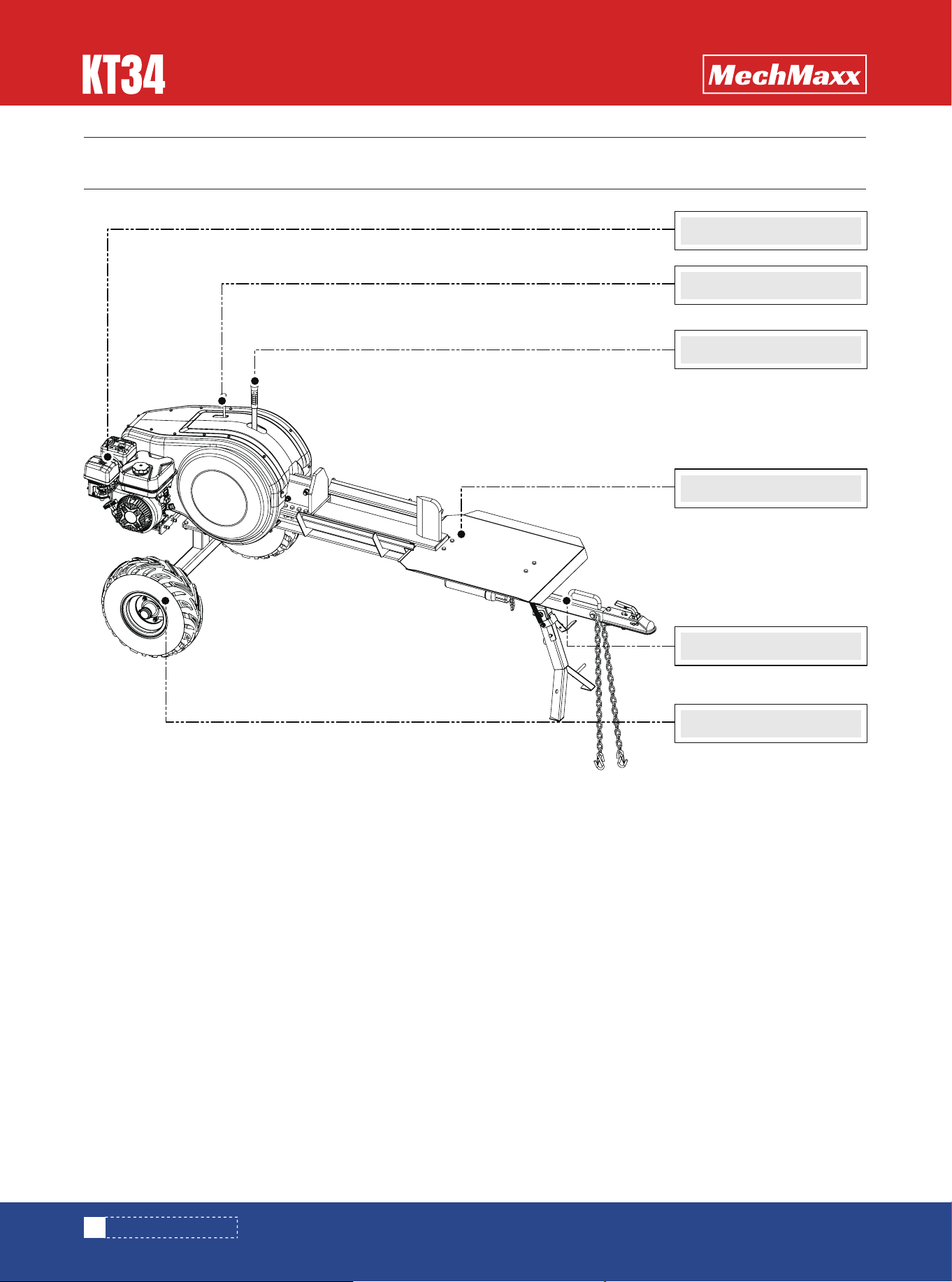
Use full-thread hex head bolts M10×30, flat washers 10,
and M10 hex thin lock nuts to assemble the tow bar to
the main frame. (See Figure 3)
Use full-thread hex head bolts M10×35, flat washers 10,
and M10 hex thin lock nuts to assemble the operation
table to the main frame. (See Figure 4)
Wheel axle
Hex bolt M10 X 30mm
Flat washer 10
4X
4X
Hex lock nut M108X
Hex bolt M10 X 25mm
Flat washer 10
8X
8X
Hex lock nut M104X
Hex bolt M10 X 30mm
Flat washer 10
4X
4X
Operation table
Figure 2
Figure 3
Figure 4
Figure 1
Spring washer 104X
Wheels
Tow bar

9
www.mechmaxx.com
ASSEMBLY
Assemble the operation handle to the main frame. (See
Figure 5)
Operation handle
Hex lock nut M104X
Hex bolt M10 X 35mm
Flat washer 10
4X
4X
Figure 5
10
www.mechmaxx.com
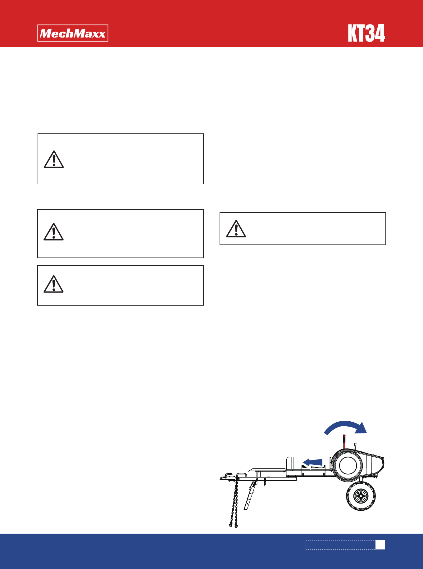
KNOW YOUR MACHINE
KNOW YOUR MACHINE
Engine
Safety handle
Operation table
Tow bar
Wheels
Operation handle
OPERATING INSTRUCTIONS
OPERATING INSTRUCTIONS
11
www.mechmaxx.com
STARTING
LOG SPLITTERING
It may be helpful to review the relevant content before
beginning the steps outlined in this chapter. This can help
you better familiarize yourself with the features of your
Log Splitter.
6. Electric Start: Turn and hold the Key in the start
position until Engine starts then let the Key return to run
position.
7. Move the choke control lever (if used for cold engine)
slowly back to the “RUN” position when the engine is
running well.
8. If the Log Splitter has not been running (cold engine),
warm up the engine by running the engine at half throttle
for 3 to 4 minutes, then advance the engine throttle
control to the maximum speed.
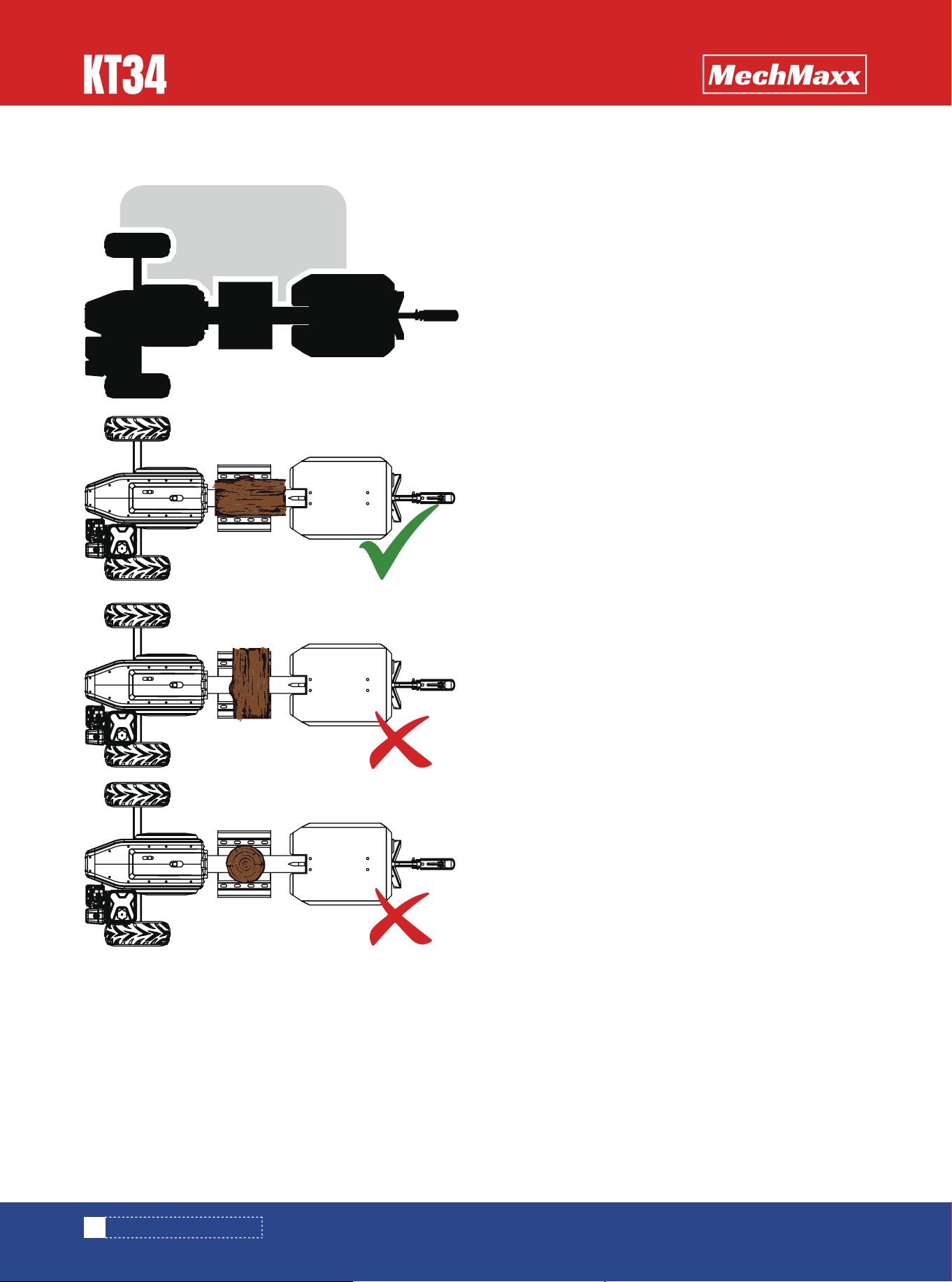
Do not place your hands on the ends of the log when
loading the log splitter. This is a very unsafe method and
could result in injury to your hands. Do not reach or step
across the rail while the log splitter is running. This is a
very unsafe method which could cause personal injury,
even death. Do not reach forward and attempt to catch
the split wood as the log is being split. Instead, let it fall
to the ground.
Place the log on the log splitter. Grasp the log on the
sides near the middle of the log. Center the log, side - to -
side, on the rail of the log splitter, making sure that one
end is against the splitting wedge.
With one hand on the lever and the other hand pushing the
start ball, pull the handle lever to ‘SPLIT’, and then remove
your hands as soon as possible, as the handle lever may
hit your hands when it retracts from ‘SPLIT’ to ‘AUTO -
RETRACT’.
1. Position your Log Splitter on flat, dry ground, and then
stop the front wheel with brake, make sure the machine
cannot be moved.
2. Make sure the fuel shut-off valve is in the “ON” position.
3. Move the choke control lever to the “CHOKE” position
(should only be needed if the engine is cold).
4. Move the throttle control lever to the “FAST” position.
5. Recoil Start: Turn the Ignition Switch to the “On”
position. Grasp the recoil starter handle and slowly pull
until you feel resistance. Let the cord retract a little bit
then pull the cord rapidly to start the engine. One or two
pulls usually starts the engine.
1. With the engine off and cool (at least two minutes),
remove the fuel filler cap and fill the tank. (See engine
manual for fuel capacity, recommended fuel type, and the
location of the fuel cap.)
2. Fill the fuel tank outdoors. Gasoline vapors can ignite
in enclosed spaces.
Note: The engine is shipped without oil.
Do not start the engine before adding oil.
Do not overfill; check the engine oil level
daily and add as needed.
All logs should be no longer than 24
inches.
Gasoline is highly flammable and explo-
sive. You can be burned or seriously
injured when handling fuel. Use extreme
care when handling gasoline.
Fill the fuel tank outdoors, never indoors.
Gasoline vapors can ignite if they collect
inside an enclosure. Explosion can result.
ADD GASOLINE TO ENGINE
12
www.mechmaxx.com
OPERATING INSTRUCTIONS
STOPPING
OPERATOR ZONE
1. Move the Throttle Lever to IDLE.
2. Recoil Start: Turn the Ignition Switch to the OFF
position.
3. Electric Start: Turn the Key to the OFF position.
OPERATOR ZONE
For engine maintenance, consult the engine manufacturer’s user manual.
ENGINE SERVICE
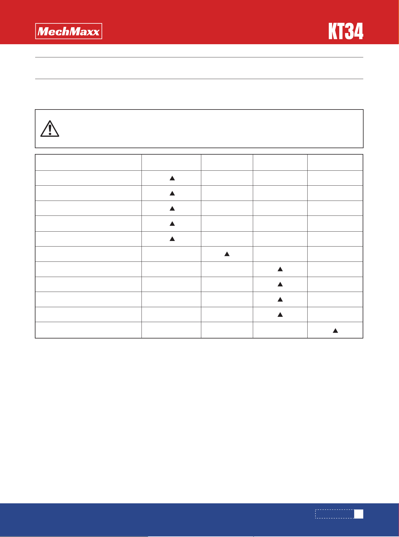
MAINTENANCE
Before Each Use
Procedure
Every 3 Hours Every 25 Hours Every 100 Hours
Check engine oil level
Check general equipment condition
Check wedge for sharpness
Grease surface of slide rail
Check belts
Grease rack and pinion
Check tire pressure
Clean engine exterior and cooling
First time 5 hoursChange Engine Oil
Replace air filter
Replace spark plug
13
www.mechmaxx.com
Before performing any maintenance procedure or inspection, stop the engine and wait five minutes
to allow all parts to cool. Disconnect the spark plug wire and keep it away from the spark plug.
Disconnect the battery terminals (Electric start only).
Regular maintenance is the key to ensuring your machine operates at its best and has a long lifespan. Please refer to this
manual as well as the engine manufacturer's user manual for maintenance procedures.
MAINTENANCE

TROUBLESHOOTING TABLE
14
www.mechmaxx.com
Before performing any maintenance procedure or inspection, stop the engine and wait five minutes
to allow all parts to cool. Disconnect the spark plug wire and keep it away from the spark plug.
Most problems can be easily fixed. Consult the Troubleshooting Table listed below for common problems and their
solutions. If you continue to experience problems, contact your local dealers.
The engine won’t start.
(Please refer to the engine
user manual for engine-specific
procedures.)
The engine lacks power or is
not running smoothly.
(Please refer to the engine
user manual for engine-specific
procedures.)
Engine smokes.
(Please refer to the engine
user manual for engine-specific
procedures.)
Is the ignition switch in the “ON” position?
Is the fuel shut-off valve on?
Are you using fresh, clean gas? If the gas is old, change it. Use a fuel stabilizer if
you keep gas longer than 30 days.
Is the spark plug clean? If the spark plug is dirty or cracked, change it. If it’s oily,
leave it out, hold a rag over the plug hole and pull the recoil cord several times to
blow out any oil in the cylinder, then wipe off the plug and reinsert it.
Check that the Throttle Lever is in the “Run” position.
Is the air filter clean? If it’s dirty, change it following the procedure in the engine
manufacturer’s owner’s manual.
Is the spark plug clean? If it’s fouled or cracked, change it. If it’s oily, leave it
out, hold a rag over the plug hole and pull your recoil cord several times to blow
out any oil in the cylinder, then wipe off the plug and reinsert it.
Are you using fresh, clean unleaded gas? If it’s old, change it. Use a fuel stabiliz-
er if you keep gas longer than 30 days.
Does your engine have the right amount of clean oil? If it’s dirty, change it
following the procedure in the engine manufacturer’s owner’s manual.
Check the oil level and adjust as needed.
Check the oil level and adjust as needed.
Check the air filter and clean or replace if needed.
You may be using the wrong oil—too light for the temperature. Refer to your
Engine Owner’s Manual for detailed information.
Clean the cooling fins if they’re dirty.
TROUBLESHOOTING
TROUBLESHOOTING
SYMPTOM
POSSIBLE CAUSE

15
www.mechmaxx.com
TROUBLESHOOTING
Rack catching on tail tube (at
end of stroke).
Rack returning very slow or not
going all the way back.
Operator Lever Snapping out of
gear or not staying in gear.
Machine does not seem to
have full splitting power.
Operator Lever not engaging
rack with pinion gear.
Rack slamming back too fast.
Adjust carriage hold downs (slide guides).
Check for wood chips or debris between ram bushing plate and beam.
Check rack lift bearing for alignment or damage.
Return spring is unhooked or damaged. Reconnect or replace as needed.
Machine wedge end too low. Must be almost level or wedge end slightly higher.
Lever not all the way forward when rack comes under full load. Push lever
quicker and more forcefully into the full forward position.
Ram has been overloaded at lower part of face. Check rack gear for straight-
ness.
Wedge end of machine too high. Must be almost level with ram end or just
slightly higher.
Springs not operating properly. Fix or replace as needed.
Clean wood chips or other debris from under rack.
Clean accumulated dirt from frame where carriage assembly rests against
rubber bumpers.
The belts may be too loose and slipping. Adjust or replace belts as needed.
SYMPTOM
POSSIBLE CAUSE
16
www.mechmaxx.com
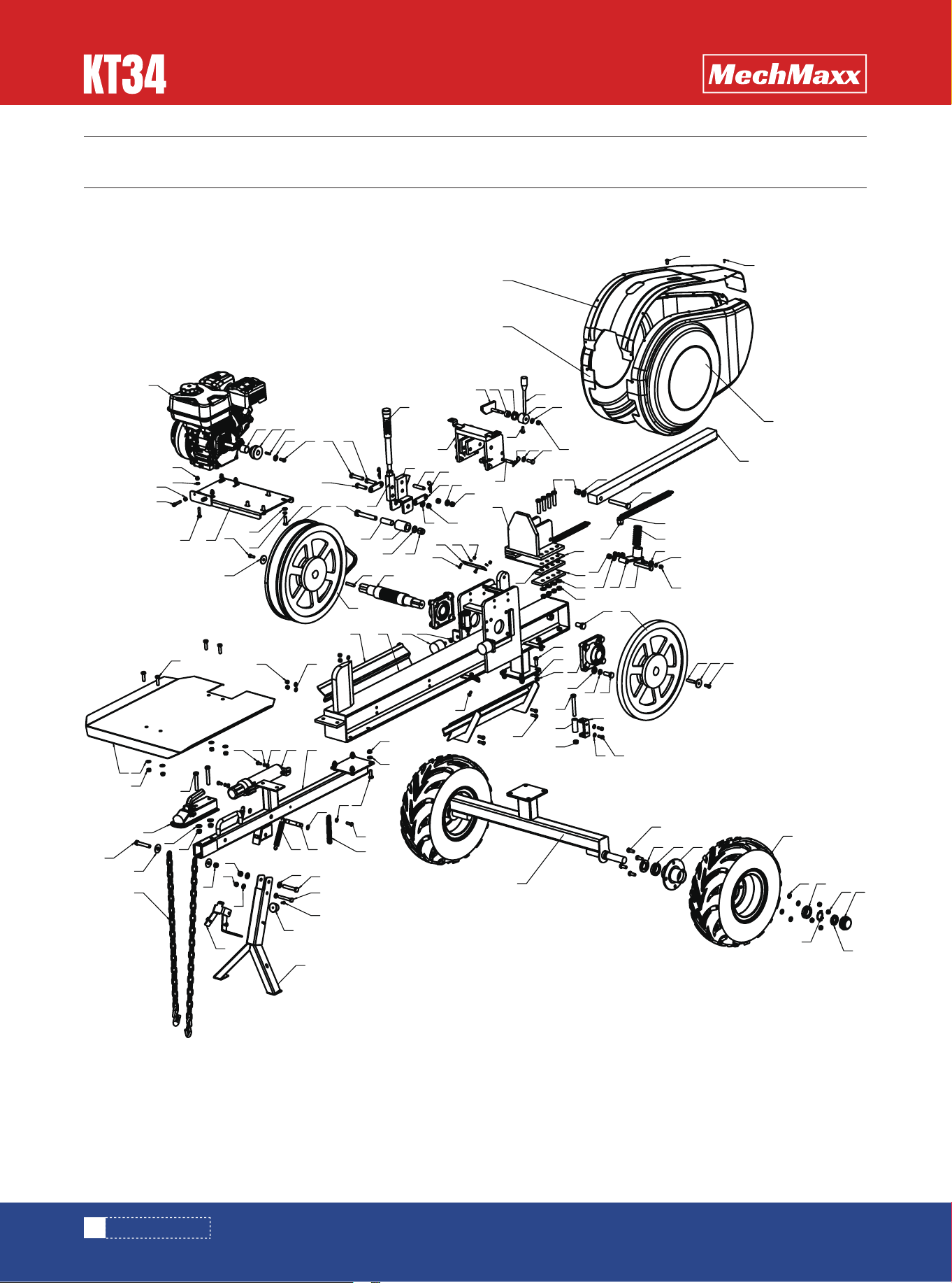
PARTS DIAGRAM
PARTS DIAGRAM
4030
19
17
18
16
99
100
89
83
94
102
101
98
131
105
48
97
42
96
89
90
91
19
95
86
19
31
88
48
42
61
52
92 93 94
87
48
42
54
1
29
30
83
72
70
71
65
29
30
108
73
60
51 20
37 48
104
46
63 64
66
67
40
7
5
6
8 9
47
47
53
49
19
31
19
31
10
4142
49
55
2
35
21
19
31
27
25
454412
43
11
62
48
4215
1314
40
23
36
32
3433
9
29
18
22
30
28
24
31
19
106
107
81
4
3
39
40
50
59
38
57
56 58
405051
68
69
42
85
115
54
42
48
109
76
114
80
113
111
79
77
75
111112
78
74
116
115
82
110

17
www.mechmaxx.com
PARTS LIST
PARTS LIST
PART NO. Description Qty
1
2
3
4
5
6
7
8
9
10
11
12
13
14
15
16
17
18
19
20
21
22
23
24
25
26
27
28
29
Main Beam Weldment
Upper Bracket Weldment
Control Lever Base Weldment
Press Block Weldment
Inner Sleeve
Roller
Hex Head Bolt Full Thread M16×100
Small Flat Washer Grade A 16
Hex Lock Nut with Non-Metallic Insert M16
Connecting Plate
Safety Lock Weldment
Limit Rubber Pad
Torsion Spring
Spring Sleeve
Spring Seat
Limit Stop Weldment
Limit Roller
Hex Head Bolt M12×90
Thin Hex Lock Nut M12
Gear Shaft
Slide Block Weldment
Spring Seat Weldment
Push Rod
Push Rod Spring
Push Rod Pad Plate
Push Rod Clamp Plate Weldment (L)
Push Rod Clamp Plate Weldment (R)
Deep Groove Ball Bearing
Hex Lock Nut with Non-Metallic Insert M8
1
1
1
1
1
1
1
1
3
2
1
1
1
1
1
2
2
3
17
1
1
1
1
1
2
1
1
2
10

18
www.mechmaxx.com
PARTS LIST
Flat Washer Grade A 8
Flat Washer 12
Hex Head Bolt Full Thread (M14)×100
Hex Lock Nut with Non-Metallic Insert (M14)
Flat Washer Grade C 14
Hex Head Bolt Full Thread M12×55
Tension Spring
Rubber Foot Pad
Square Flange Bearing Unit
Hex Head Bolt Full Thread M16×30
Hex Head Bolt Full Thread M8×20
Hex Head Bolt Full Thread M10×25
Flat Washer 10
Hex Head Bolt Full Thread M6×16
Flat Washer Grade C 6
Hex Lock Nut with Non-Metallic Insert M6
Hex Head Bolt Full Thread M12×60
Hex Head Bolt Full Thread M12×45
Thin Hex Lock Nut M10
R-Clip Pin
Oversized Flat Washer Grade C 8
Parallel Key Type C 10×8×45
Hex Head Bolt Full Thread Grade C M10×35
Headless Pin Shaft 12×60×3.2
Hex Head Bolt Full Thread Grade C M10×30
Headless Pin Shaft 10×40×3.2
Spring Washer (14)
Flat Washer 14
Hex Head Bolt Full Thread (M14)×35
Small Flywheel
Small Belt Pulley
Worktable Weldment
15
14
1
1
1
8
2
2
2
2
8
4
24
2
2
2
1
2
16
9
2
2
4
1
8
4
8
8
8
1
1
1
PART NO. Description Qty
30
31
32
33
34
35
36
37
38
39
40
41
42
43
44
45
46
47
48
49
50
51
52
53
54
55
56
57
58
59
60
61

19
www.mechmaxx.com
PARTS LIST
Safety Handle
Engine Shaft Sleeve
Engine Pulley
Round Head Square Neck Bolt M8×40
Parallel Key 4.7×5.1×25
Large Flat Washer Grade C 8
Hex Head Bolt Full Thread M10×30
Standard Spring Washer (Assembly) 10
Hex Socket Cap Screw M8×40
Hex Nut M8
Engine
Belt
Axle Weldment
Wheel Flange Welded Assembly
Rear Axle End Cover
Wheel Assembly
Hex Head Bolt Full Thread M10×25
Flat Washer Grade C 10
Thin Hex Lock Nut with Non-Metallic Insert M10
Guard Top Plate
Hex Socket Button Head Screw M6×16
Hex Head Bolt Full Thread M8×25
Light Duty Spring Washer (Assembly) 8
Tow Bar Weldment
Connector
Small File Tube
Hex Head Bolt M12×75
Hex Head Bolt Full Thread M12×70
Large Flat Washer 12
Chain
Hex Head Bolt M8×16
Spring Washer 8
1
1
1
4
1
1
4
4
2
2
1
1
1
2
2
2
8
8
8
1
1
5
1
1
1
1
2
2
2
2
2
2
PART NO. Description Qty
62
63
64
65
66
67
68
69
70
71
72
73
74
75
76
77
78
79
80
81
82
83
84
85
86
87
88
89
90
91
92
93

20
www.mechmaxx.com
PARTS LIST
Flat Washer 8
Thin Hex Lock Nut with Non-Metallic Insert M12
Flat Washer 12
Hex Head Bolt Full Thread M10×70
Shaft Retaining Ring Type A 15
Support Leg Weldment
Rubber Damper
Spring Pin Shaft
Chain
Spring
Operating Handle
Support Leg Stop Weldment
Left Guard Weldment
Right Guard Weldment
Engine Mount Plate Weldment
Slider Pad Plate
Wooden Frame Weldment
Tapered Roller Bearing 320/28
Double-Lip Oil Seal 28×52 (Assembly Type)
Lock Washer for Round Nut 27
Round Nut M27×1.5
Hex Socket Button Head Screw M8×16
Phillips Half-Countersunk Self-Drilling Screw ST4.2×13
3
1
2
1
2
1
1
1
1
2
1
1
1
1
1
1
1
4
2
2
2
6
14
PART NO. Description Qty
94
95
96
97
98
99
100
101
102
103
104
105
106
107
108
109
110
111
112
113
114
115
116