

Operator’s Manual
www.mechmaxx.com
WARRANTY

1
www.mechmaxx.com
FOREWORD
FOREWORD
NOTICE
The location of the Operator's Manual
The Operator's Manual is used for safety guidelines and the correct use and maintenance of the machine. The operation
and maintenance steps described are the most effective methods for operation and maintenance. Following these
instructions helps to ensure the effectiveness, economy and reliability of equipment maintenance. Careful reading of the
relevant contents of "NOTICE" and "WARNING" in the driver's manual will minimize the risk of casualties and machine
damage or unsafe factors caused by improper maintenance.
•This manual is applicable to MEC17.
•This manual has been adapted to all markets. Optional and special equipment from different markets should be ignored
because they may not be suitable for your machine.
•We reserve the right to modify and improve technical data, specifications, design, operation and maintenance instruc-
tions of the product without prior notice.
•It is forbidden to modify the electrical system of the machine. If any abnormal or damaged components are caused by
this, the company will not be responsible for it.
In addition to this manual, please refer to the instruction manual of the engine for details on the use, maintenance, and
troubleshooting of the engine.
In the book where the requirements for the safety of people, machine and important technology in place, all have symbol
prompts and●, please bear in mind.
•Storage location for the Operator’s Manual:
•magazine box on the back of operator’s seat.
• Before starting and operating the machine for the first time, and before repairing the machine, you
should read the instructions carefully and understand thoroughly.
• Read the safety messages and safety labels given in this manual carefully so that they should be
understood fully.
• This manual should always be placed next to the machine for easy reference, if the manual is lost,
damaged or illegible should be replaced.
• When you sell the machine, make sure that this manual should be provided to the new owner
together with the machine
WARNING

Vehicle Operation and Maintenance
TABLE OF CONTENTS
TABLE OF CONTENTS
SAFETY REGULATIONS
EQUIPMENT OUTLINE
2
4
4
Introduction
5
Warning Signs and Illustrations
5
SAFETY
10
OPERATION
35
10
Safety Machine Operation
22
Transport
27
Battery
28
Battery Safety Operation
28
Towing and Being Towed
30
Lifting Work
30
Safety Maintenance Information
31
General Drawing of Control Device
35
Description of Instrument and Control Device
36
Other Control Devices
43
Equipment Lock
46
Battery Disconnect Switch
47
Machine Operations and Controls
48
Checks before Starting
48
Coolant Level: Check or Add
49
Oil Level in Engine: Check or Add
49
Fuel Level: Check or Add
50
Oil Level of Hydraulic :Check or Add
51
Air Cleaner Dust Indicator (optional): Check
52
Electric Wiring: Check
53
Seat Adjustment
53
Operations before Starting Engine
54
Starting Engine
55
Starting Engine in Cold Weather
56
Warming up operation
57
Machine Operation: Move and Stop
58
Moving Machine Backward
59
Stopping Machine 60
Steering the Machine
Swinging
Work Equipment Controls and Operations
60
61
61
Operation with Hook Bucket
63
Permissible Depth of Water
66
Traveling on Slopes
67
Cold Weather Operation
68
After Daily Work Completion
68
After Cold Weather Season
69
Long Term Storage
69
Troubles and Actions
70
Others Malfunction
75
Electrical System
76
Maintenance Information
79
Lubricants, Fuels and Coolants
80
Wear Parts
83
Correct Selection
84
Tightening Torque Specifications
84
Safety critical parts
86
Maintenance Interval for Hydraulic Breaker
89
Maintenance procedures
89
Fan belt - check/adjust
90
Fuel system maintenance and maintenance
91
Fuel system - exhaust
92
Maintenance of cooling system
92
Internal cooling system - cleaning/replacement
93
Air filter maintenance and maintenance
93
Operation instructions for electric welding
97
Maintenance of Hydraulic System
97
Hydraulic Oil Replace
98
Hydraulic System - Exhaust
100
Operator Instructions
103
79
MAINTENANCE
103
VIBRATORY COMPACTOR QUALITY WARRANTY
CERTIFICATE
2
www.mechmaxx.com
SPECIFICATIONS

3
www.mechmaxx.com
Eccentric Assembly Maintenance and Usage
103
Pipeline
103
Hydraulic Oil Usage
103
Bolts and Nuts Usage & Maintenance
103
Operating Method
103
Special Notes
103
Warranty Scope
104
Specifications
105
Working Ranges
107
Lifting Capacity Form
108
Standard Configuration and Digging Force
109
Operating Weight and Ground Specific Pressure
109
Safety First
110
Precautions when removing or installing
110
Attachment Installation
111
Recommended Attachment Operations
111
Hydraulic Breaker
111
Prohibited Works
112
Supply Grease in the Correct Position
113
Special Notes for Hydraulic Vibratory Compactor Use
104
105
SPECIFICATION
110
ATTACHMENTS AND OPTIONS
SAFETY SIGNS

4
www.mechmaxx.com
SAFETY REGULATIONS
SAFETY REGULATIONS
Vehicle Operation and Maintenance
To operate and use the machine, you must follow the rules and regulations issued by national, provincial, autonomous
region, and government. Therefore, the operating instructions and safety information contained in this manual are merely
some helpful advice.
The following symbols together with texts mean the following as they appear in this manual:
In addition to the above, the following signal words are used to indicate precautions that should be followed to protect
the machine or to give information that is useful to know.
NOTICE
This word Indicates that when the wrong operation is carried out, it may cause damage to the machine or shorten the
service life of the machine.
REMARKS
This word is used for information that is useful to know.
• Warning, keep alert! It concerns your own safety!
• Ignorance of such risk may result in accident, serious injury even death.
• It’s the operator’s liability to ensure that all warning signs are kept on the machine in good condi-
tion and legibly. Otherwise accident is most likely to occur.
• Familiarize with the functions and limitations of the machine.
WARNING
• Before operating the machine, the operator must have sufficient operational skills and have read
up and understood the related content of the manual.
• Untrained operators may result in the risk of serious injury or personal death.
• Never use a machine without the Operator’s Manual.
• Before operating this machine, familiarize with various warning signs, symbols and the operator’s
manual of this vehicle.
WARNING
5
www.mechmaxx.com
EQUIPMENT OUTLINE
EQUIPMENT OUTLINE
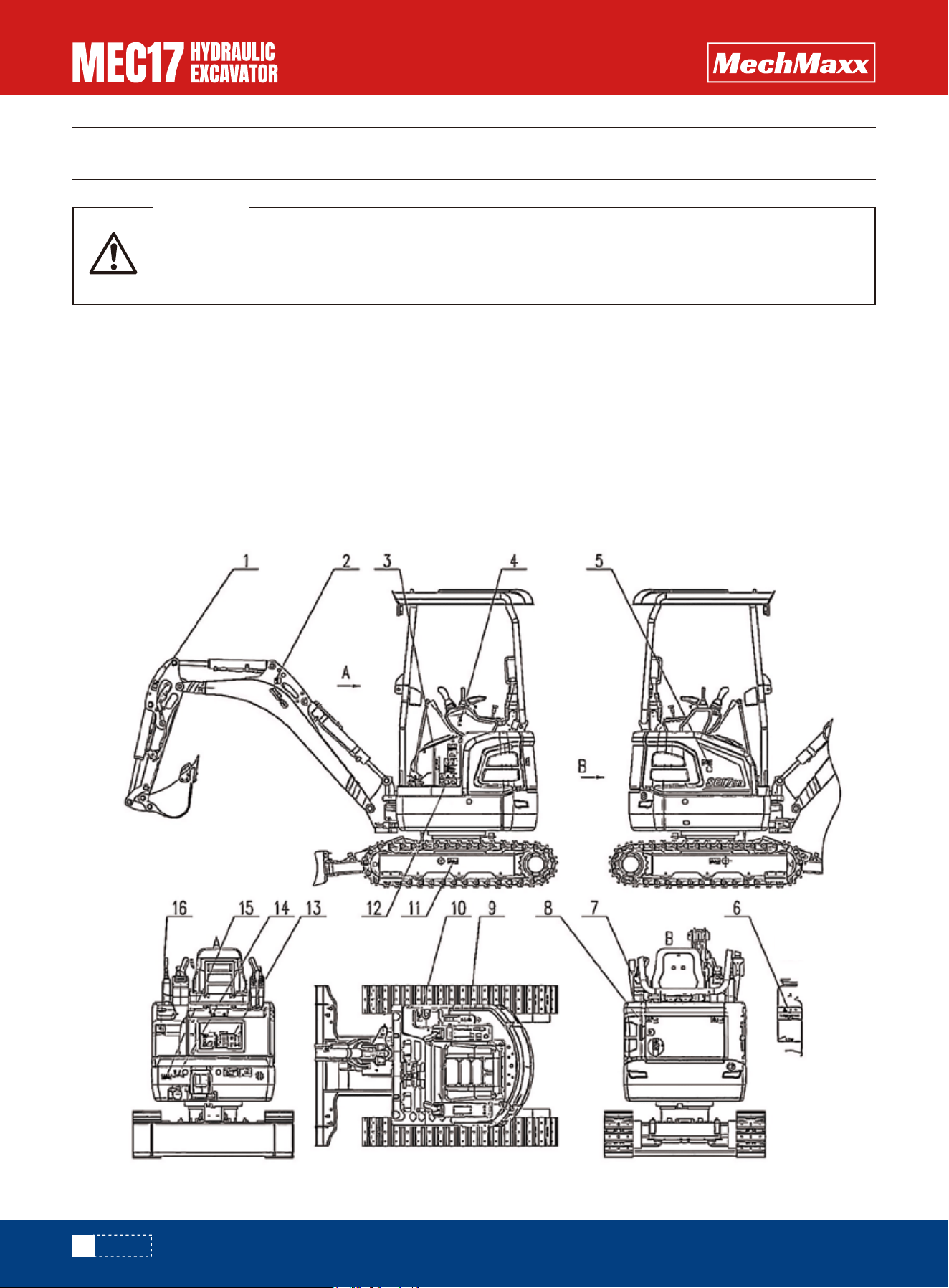
Introduction
Specified Use
The machine is intended to be used under normal conditions for the applications described in this manual. If it is used for
other purposes or in potentially dangerous environments, for example explosive atmosphere, flammable environment or
areas with dust containing asbestos and so on, special safety regulations must be followed and the machine is equipped
for such use.
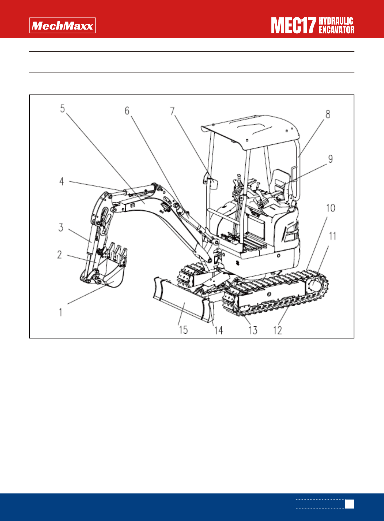
1.Bucket
2.Arm
3.Bucket cylinder
4.Arm cylinder
5.Boom
6.Boom cylinder
7.Water cup holder
8.Driver's shed
9.Seat
10.Track
11.Traveling motor and drive sprocket
12.Support wheels
13.Increase assembly
14.Bulldozer cylinder
15.Bulldozer
6
www.mechmaxx.com
EQUIPMENT OUTLINE
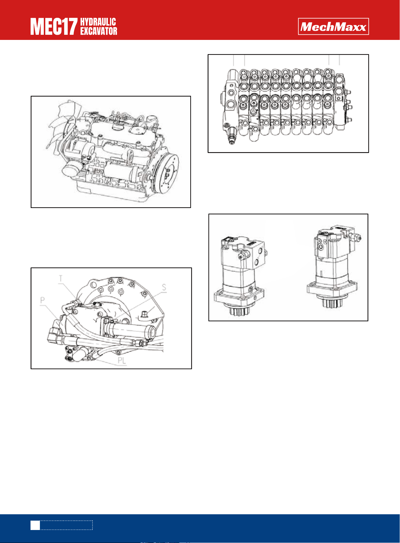
Engine
MEC17 Engine is 3 cylinders, 4 stroke, water-cooling,
0.898L displacement, KUBOTA D902 type, rated power:
11.8kW/2300rpm.
Main Pump
Hydraulic pump is a hydraulic component which converts
mechanical energy into liquid pressure energy. It consists
of a variable ram pump. Constant power plus load sensi-
tive control mode is adopted.
Swing Motor and Reducer
The slewing motor is a orbit motor, including determinant,
vanes, drive shafts, relief valves, one-way valves, etc.
This slewing motor has no reducer, and it outputs large
torque directly through the drive shaft.
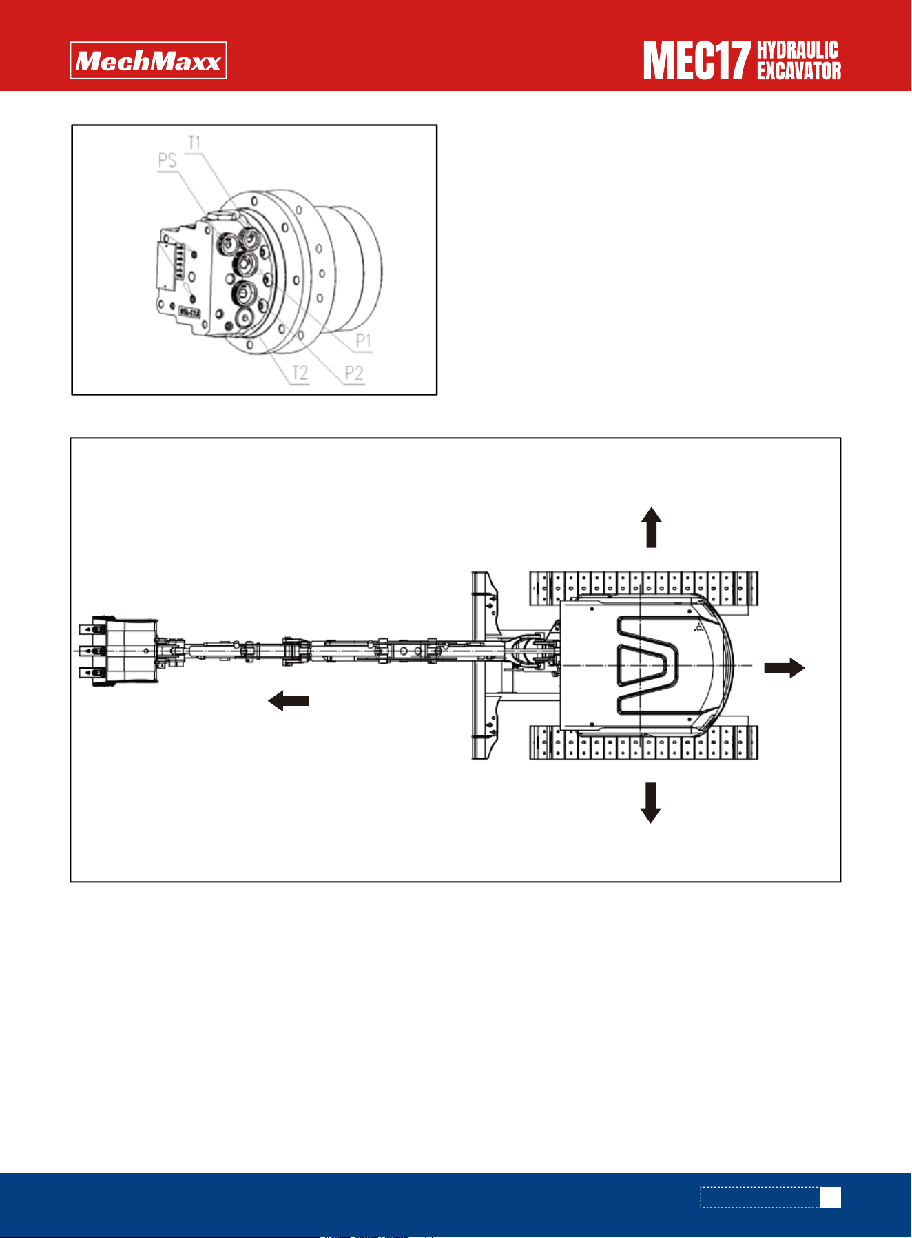
Travel Motor and Reducer
Travel motor and reducer contains the travel motor and
the gear reducer. The travel motor is a swash plate axial
piston motor that also include plunger, inclined plate,
brake valve, balance valve, flow control valve, etc .
The reducer is composed of the sun gear, the planetary
gear, the pinion gear and the gear housing.
The high speed and small torque output from the main
shaft of the walking motor changes into low speed and
large torque after deceleration by the reducer. Two-speed
switching can correspond to different working conditions.
Main Valve
The main valve consists of 11 valve plates. 11 valves
including first coupling valve, stick valve, boom valve,
bucket valve, spare valve, boom deflection, rotary valve,
left travel valve, right travel valve, bulldozing The shovel
valve is connected to the end of the valve. (Please refer
to the actual product for the specific order).
7
www.mechmaxx.com
EQUIPMENT OUTLINE
NOTE
If the above description is inconsistent with the products
sold, it should be based on the substance delivered, not
on this manual as the basis of the product style. If the
product style or configuration changes, no notice will be
given.
In this operator's manual, the state of the machine's traveling direction (front) as seen from the driver's shed is the basic,
which determines the front, rear, left, and right of the machine.
Directions of Machine
A Front B Rear C Left D Right
A
D
C
B
8
www.mechmaxx.com
EQUIPMENT OUTLINE
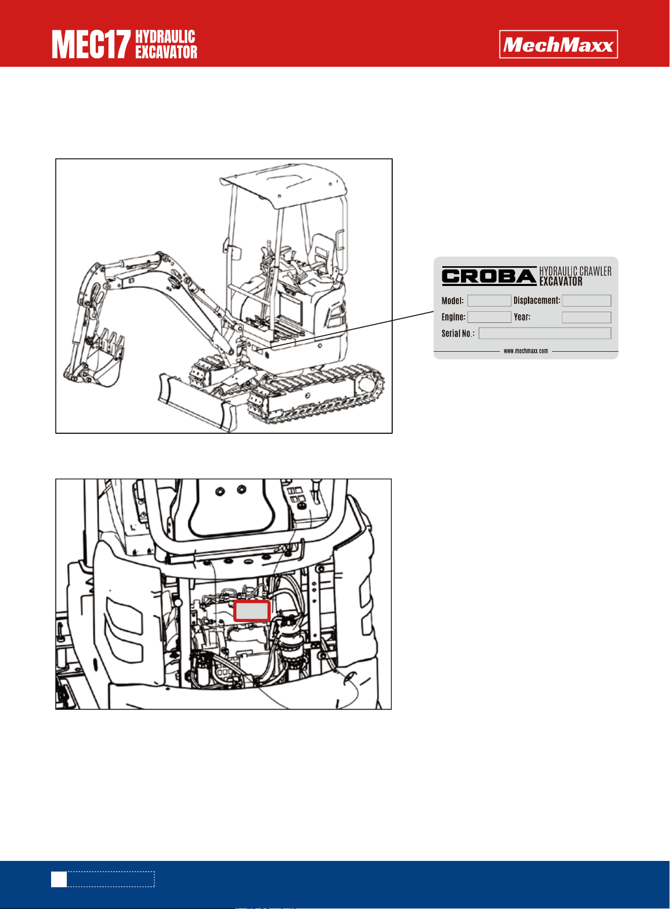
The following instructions and words are the product identification and nameplate on the machine.
When you need to maintain the machine or order parts, please inform Mechmaxx Distributor of the following content.
Located on the left front side of the rack.
On the top of the engine cylinder head cover.
Environmental Information Labels and Product Nameplates
Engine Number Plate
MEC17
2025
Kubota D902
0.898L

9
www.mechmaxx.com
EQUIPMENT OUTLINE
The display frame selects the area, and it automatically displays “working time”.
Service Meter Location
10
www.mechmaxx.com
SAFETY
SAFETY
The following warning ,information, and text instructions are used on this machine.
•Be sure that you fully understand the correct position and content of labels.
•To ensure that the content of labels can be read properly, be sure that they are in the correct place and always keep
them clean.
•There are also other labels in addition to the warning signs and safety labels. Handle those labels in the same way.
•If the labels are damaged, lost, or cannot be read properly, place an order with Mechmaxx.
Warning Signs and Illustrations
Location of Warning Signs and Illustrations
Please read and make sure that you fully understand the precautions described in this manual and
the safety labels on the machine. When operating, maintaining and inspecting the machine, always
follow these precautions strictly.
WARNING
11
www.mechmaxx.com
SAFETY
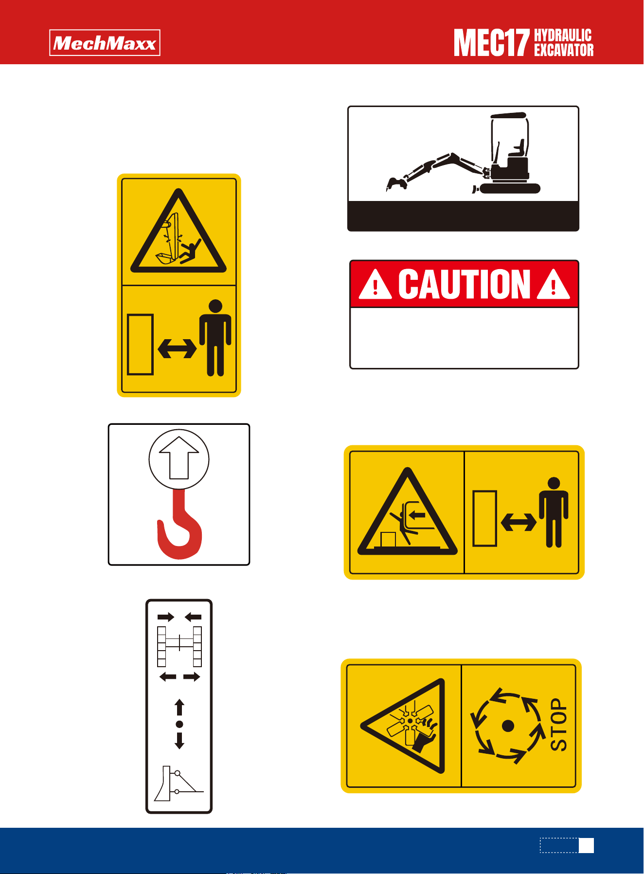
Beware of work equipment
•Sign indicates a hazard of being hit by the working
Device of the machine.
•Keep away from machine during operation.
7. Safety notice sign for turning area
•Do not enter the turning area of the machine when the
upper part of the machine is turning.
•There is a danger of collision when the platform rotates.
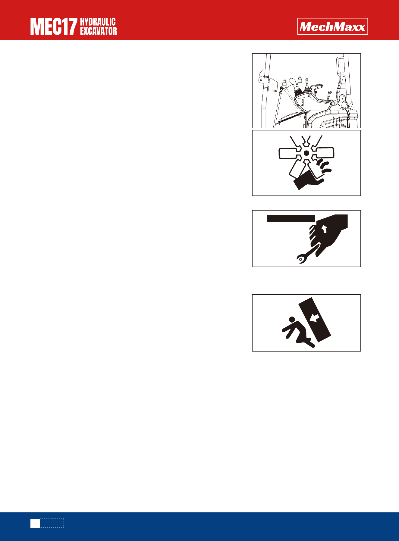
8. Note signs for engine operation
•When the fan is running, it is forbidden to touch or repair
it.
•After stopping the operation, perform maintenance.
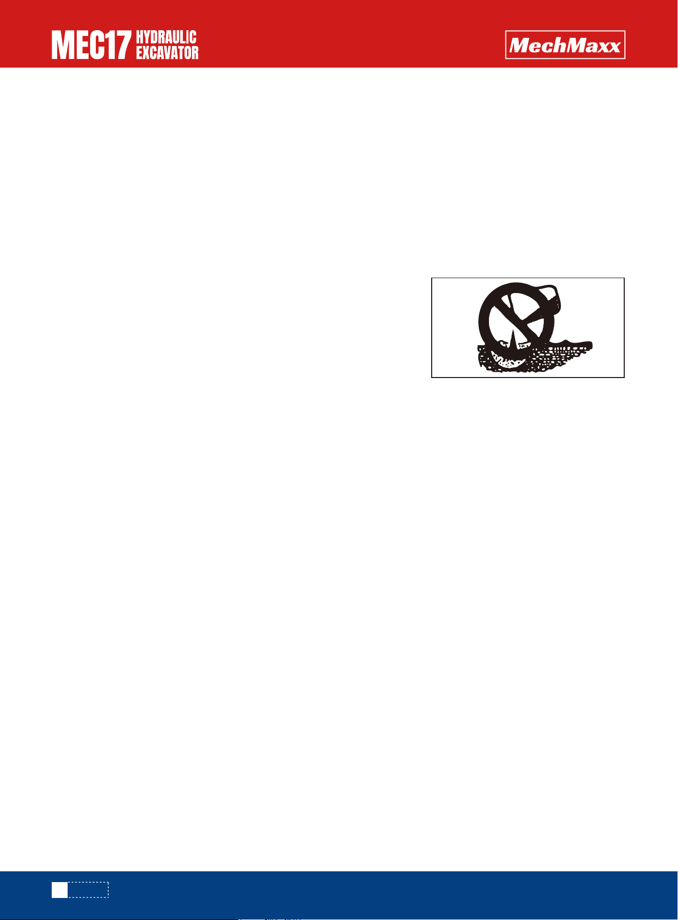
2. Lifting position sign.
3. Bulldozing and telescopic switch signs.
4. Hydraulic oil level check posture sign
5. Coolant pay attention to the label
Safety Labels
Check hydraulic oil level in this posture.
Check the water level in
the tank everyday.
12
www.mechmaxx.com
SAFETY
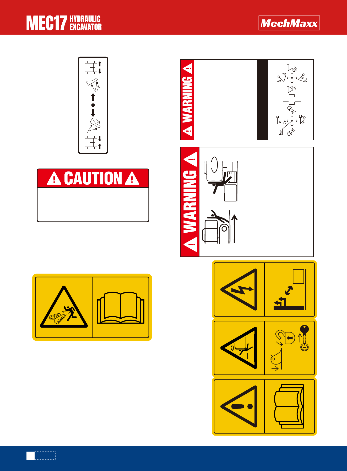
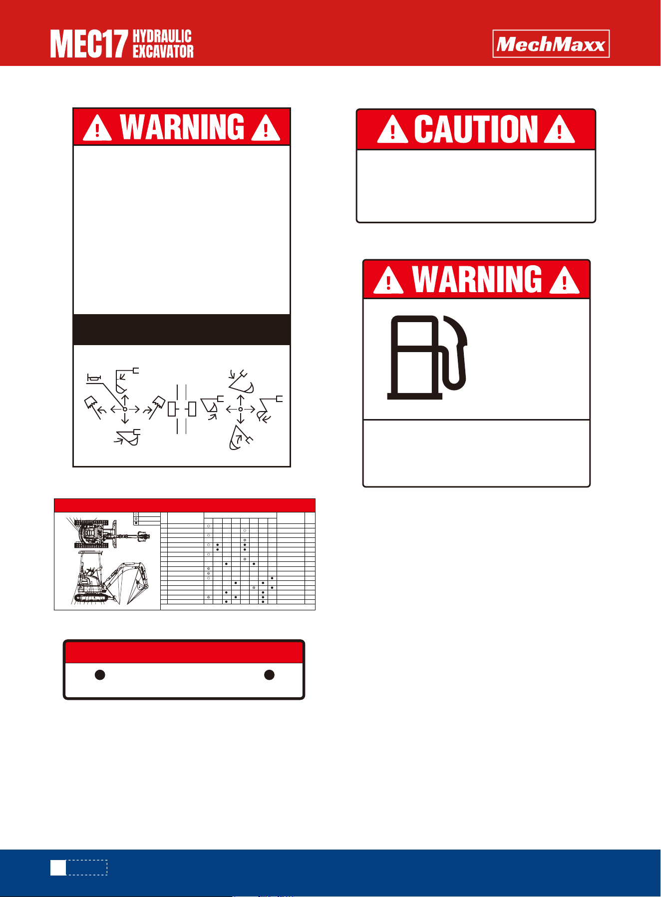
9. Bulldozer and telescopic control sign
10. Fuel tank cap warning sign
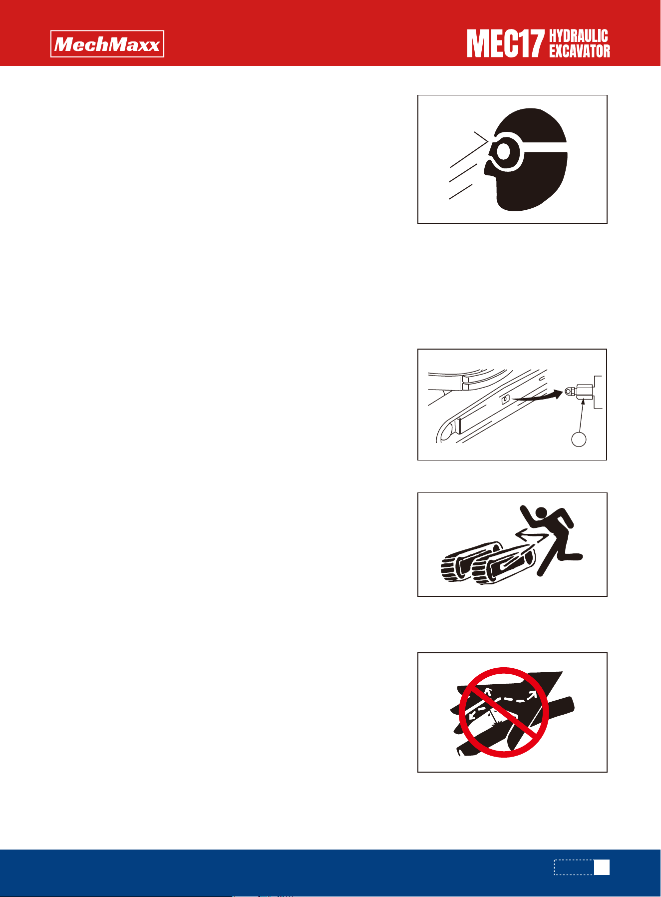
11. Note signs for track adjustment
•The screw plug of the track shoe tension adjustment
device will fly out and cause injury.
•When adjusting the track tension, read this driver's
manual and follow the correct method.
12.
The through hole in the
middle of the fuel tank cover
is the air hole, Which is
forbidden to be blocked.
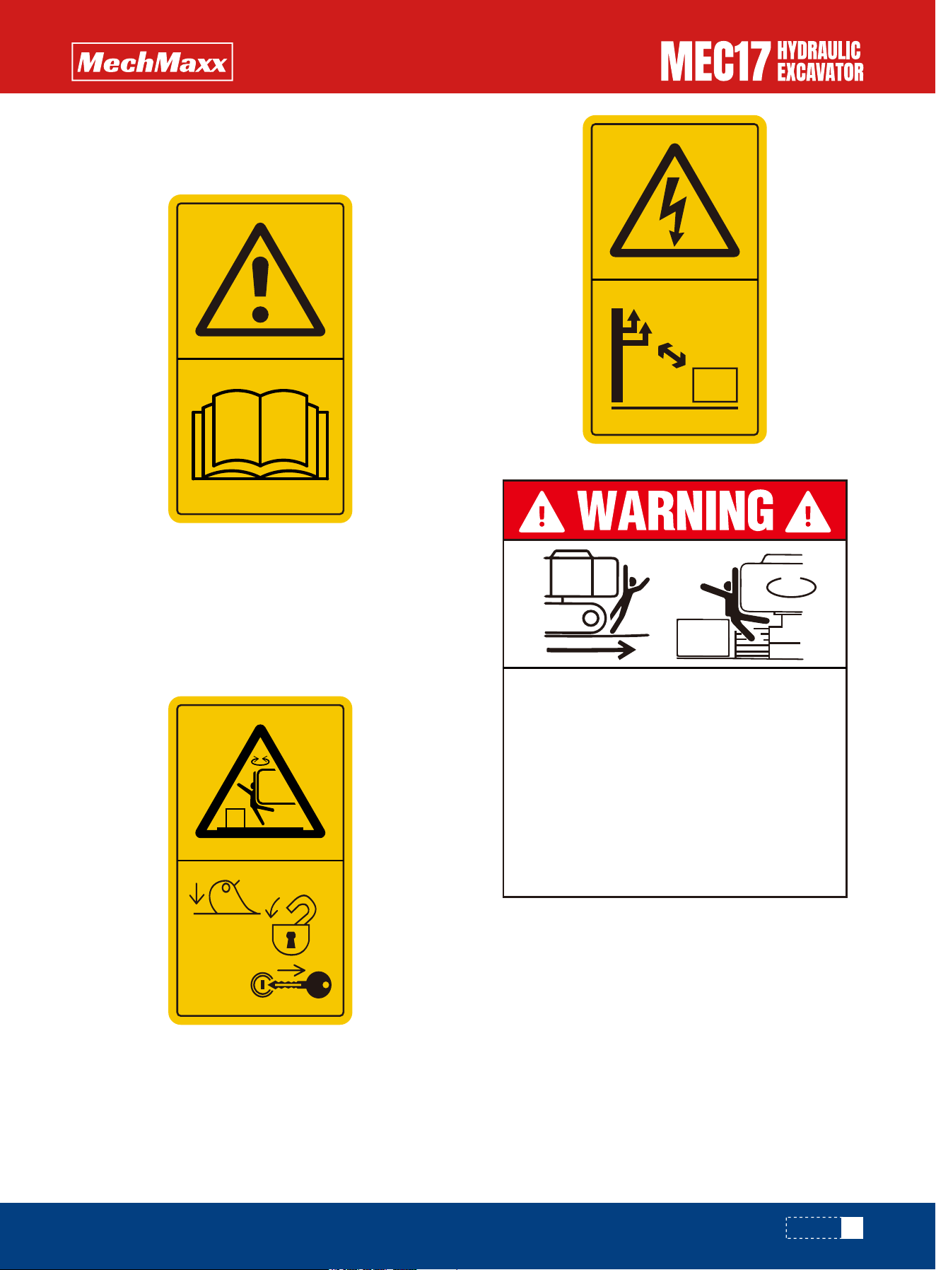
To prevent severe injury or death, do the
following before moving machine or it's
attachments:
• Honk horn to alert people nearby.
• Be sure no one is on or near machine or in
sawing area.
• Rotate cab for full view of travel path if it can
be done safely.
• Use spotter if view is obstructed. Follow
above even if machine equipped with travel
alarm and mirrors.
In order to prevent an accident
resulting in injury or death caused
by error operation, confirm the
machine motion and indicated
operating pattern when operating
machines, pay attention to the
circumference and operate slowly
when confirming the machine
motion.
ISO MODEL
13
www.mechmaxx.com
1) Note signs before operation
•Read the driver's manual before operation, maintenance,
assembly and transportation
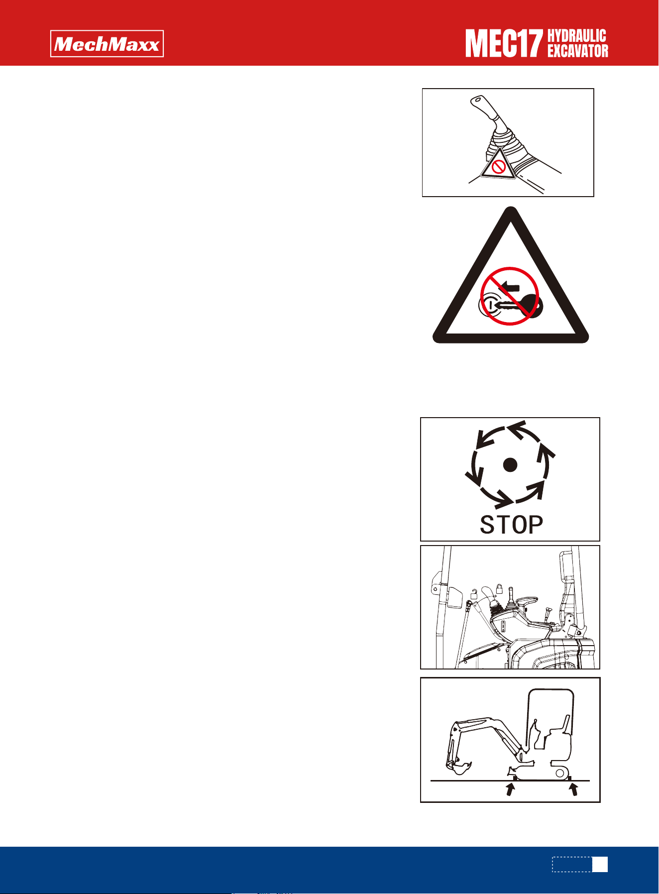
2) Start and stop safety signs
•The sudden movement of the stopped machine may
cause the danger of being caught or run over by the
machine. When leaving the machine, lower the working
device to the ground,
•Move the safety lock lever to the locked position and
remove the engine key.
3) High Voltage Attention Sign
•If the machine is close to high-voltage cables, it may
cause electric shock to the operator.
•Keep a safe distance between the machine and the
cable.
4) Caution signs before reversing.
To prevent severe injury or death, do the
following before moving machine or it's
attachments:
• Honk horn to alert people nearby.
• Be sure no one is on or near machine or in
sawing area.
• Rotate cab for full view of travel path if it can
be done safely.
• Use spotter if view is obstructed. Follow
above even if machine equipped with travel
alarm and mirrors.
SAFETY
14
www.mechmaxx.com
13. Maintenance and replacement table
14. Filling position signs
5) Caution for operating pattern (ISO mode). 15. Lubrication plate of slewing bearing
16. Dangerous signs for fuel filling
In order to prevent an accident
resulting in injury or death caused
by error operation, confirm the
machine motion and indicated
operating pattern when operating
machines, pay attention to the
circumference and operate slowly
when confirming the machine
motion.
ISO MODEL
Swing bearing Swing gear
GREASE INJECTION POINT
Fill grease every 250 hours
(Don't fill frequently)
Stop the engine when filling the
fuel,and keep all the lights and
fire in a safe distance.
FUEL
DIESEL OIL
SAFETY
MAINTENANCE AND REPLACEMENT CHART
No.
1
2
3
4
5
6
7
8
9
10
11
12
13
14
15
16
17
Working Device Pins
Slewing Bearing
Coolant
Radiator
Engine Oil
Engine Oil Filter
Fuel
Water & Sediment in Fuel fork
Fuel Fine Filter
Fuel Coarse Filter
Oil&Water Segregator
Hydraulic Oil
Return Filter
Suction Filter
Travel Drive
Air Filter
Pilot Filter
Maintenance Items
Every
Day
Initial
50h
Initial
500h
Initial
1000h
Every
250h
Every
500h
Every
1000h
Every
2000h
Grease NLG1#2
Grease NLG1#2
-45# Every 3000h
Dustproof Mesh
API CI-4 SAE 15W-40
API CI-5 SAE 85W-90
Main Filter Safety Filter
NOTICE: 1.Stop engine for maintenance and replacement. 2.Please refer to the Operator's Manual for other details.
Filter
S<0.15%
Replace
Check and Clean
Clean and refill
Fine Filter
ISO VG46
Filter
Filter
Filter
5.05L
3.7L
1
19L
1
1
21.5L
1
2x0.3L
Each
1
Hours and Intervals
Materials
QTY
11
4
59101116
87
13142631517 12
15
www.mechmaxx.com
Safety Rules
If Problems are Found
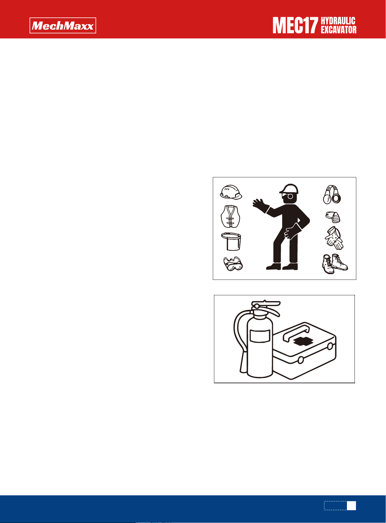
Working Wear and Personal Protective Items
Fire Extinguisher and First Aid Kit
Safety Equipment
Basic Safety Information
•Only trained and authorized personnel can operate and maintain the machine.
•Follow all safety rules, precautions and instructions when operating or performing maintenance on the machine.
•Do not operate the machine if you are in poor physical condition and mental instability, under the influence of drugs
(easily drowsy) or alcohol.
•When working with another operator or configuring a signal person, be sure that all personnel understand all hand
signals that are to be used.
•Do not wear loose clothing and accessories. There is a hazard
that they may catch on control levers or other protruding
parts.
•If you have long hair and it hangs out from your hard hat, there
is a hazard that it may get caught up in the machine, so tie
your hair up and be careful not to let it get caught.
•Always wear a hard hat and safety shoes. If the nature of the
work requires it, wear safety glasses, mask, gloves, ear plugs,
and safety belt when operating or maintaining the machine.
•Check that all protective equipment functions properly before
using it.
Always follow the precautions below to prepare for action if any
injury or fire should occur.
•Be sure that fire extinguishers have been provided and ensure
that you know their use well in emergencies.
•Carry out periodic inspection and maintenance to ensure that
the fire extinguisher can always be used.
•Provide a first aid kit in the storage point. Carry out periodic
checks and add to the contents if necessary.
•Be sure that all guards, covers and rear view mirror are in their proper position. Have guards and covers repaired immedi-
ately if they are damaged.
•Understand the method of use of safety features and use them properly.
•Never remove any safety features. Always keep them in good operating condition.
If you find any problems in the machine during operation or maintenance (noise, vibration, smell, incorrect gauges, smoke,
oil leakage, etc., or any abnormal display on the warning devices or monitor), report to the person in charge and have the
necessary action taken. Do not operate the machine until the problem has been corrected.
SAFETY
16
www.mechmaxx.com
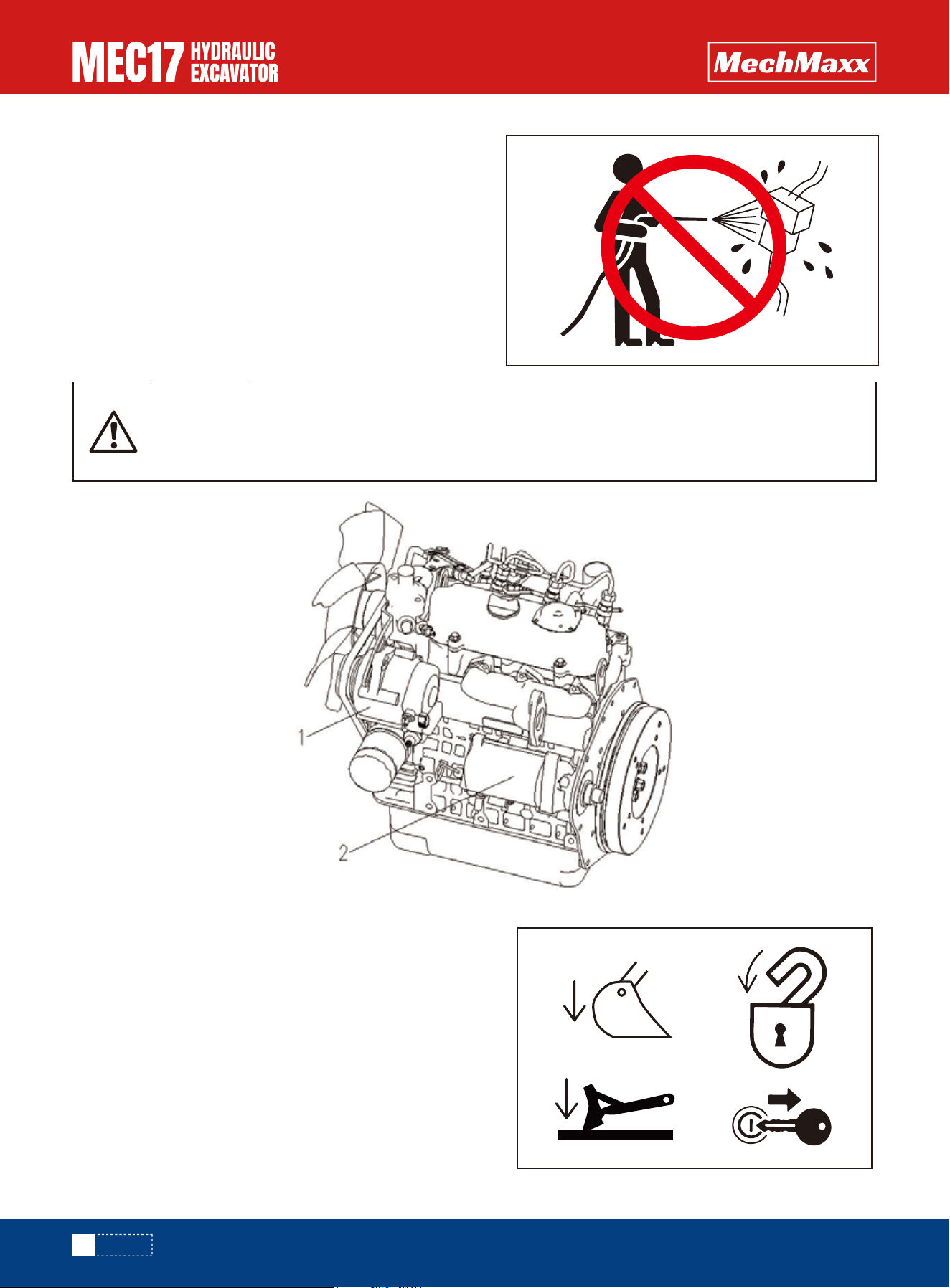
Keep Machine Clean
Precautions of Standing up or Leaving from the Operator's Seat
•If water gets into the electrical system, there is a hazard that
it will cause malfunctions or misoperation. Do not use water
or steam to wash the electrical system (sensors, alternators,
solenoid valves, connectors).
•If inspection and maintenance is carried out when the
machine is still dirty with mud or oil, there is a hazard that you
will slip and fall, or that dirt or mud will get into your eyes.
Always keep the machine clean.
•Before standing up from the seat (for example, when adjust-
ing the seat, etc.), lower the working device to the ground
completely. At the same time, move the lock lever to the
locked position, and then turn off the engine. If you accidental-
ly touch the unlocked joystick, the machine may move
suddenly and cause a serious personal accident.
•When leaving the machine, you must lower the working device
and the bulldozer to the ground, place the lock lever in the
locked position, and stop the engine. In addition, lock all
equipment with a key. Take down the key and put it in the
specified position.
When cleaning the engine around, the following two can not be cleaned and splashed liquid, other-
wise it will cause damage of engine parts.
1. Generator; 2. Starting motor
WARNING
SAFETY
17
www.mechmaxx.com
Use Handrails and Stairs Leaving Operator's Seat
Forbidden to Jump On or Off the Machine
No Persons on Attachments
•To prevent burns from hot water or steam spurting out when checking
or draining the coolant, wait for the water to cool to a temperature
where it is possible to touch the radiator cap by hand before starting
the operation. Even when the coolant has cooled down, loosen the cap
slowly to relieve the pressure inside the radiator before removing the
cap.
To prevent personal injury caused by slipping or falling off the machine, always do as follows:
•To ensure safety, always face the machine and maintain three-point contact (both feet and one hand, or both hands and
one foot) with the handrails and steps (including the track shoe) to ensure that you support yourself.
•Do not grip the control levers or lock lever when getting on or off the machine.
•Never climb on the engine hood or cover that does not have anti-skid devices.
•Before getting on or off the machine, check the handrails and steps (including the track shoe). If there is any oil, grease,
or mud on the handrails or steps (including the track shoe), wipe it off immediately. Always keep these parts clean.
Repair any damage and tighten any loose bolts.
•Do not get on or off the machine while holding tools in your hands.
•Never jump on or off the machine. Never get on or off a moving machine.
•If the machine starts to move when there is no operator on the machine, do not jump on to the machine and try to stop
it.
Never let anyone ride on the work equipment, or other attachments. There is a hazard of falling and suffering serious
injury.
Not to Be Pinched
Due to the action of the connecting rod, the peripheral clearance of the working device will change. If caught, it may cause
a serious personal accident. Personnel are not allowed to approach all rotating and telescopic parts.
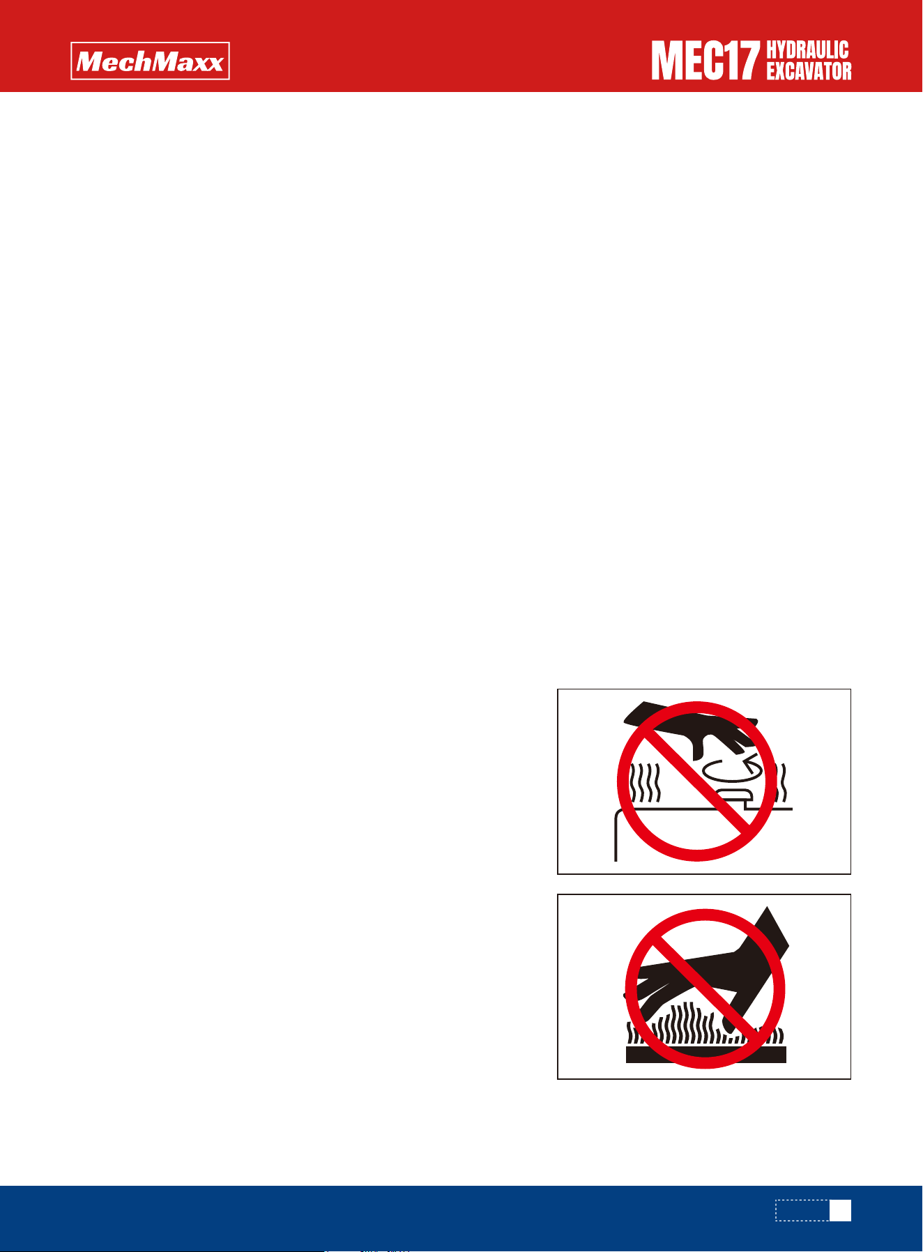
Burn Prevention
Hot coolant
•To prevent burns from hot oil spurting out when checking or draining
the oil, wait for the oil to cool to a temperature where it is possible to
touch the cap or plug by hand before starting the operation. Even
when the oil has cooled down, loosen the cap or plug slowly to relieve
the internal pressure before removing the cap or plug.
Hot oil
Due to the action of the connecting rod, the peripheral clearance of the working device will change. If caught, it may cause
a serious personal accident. Personnel are not allowed to approach all rotating and telescopic parts.
SAFETY
18
www.mechmaxx.com
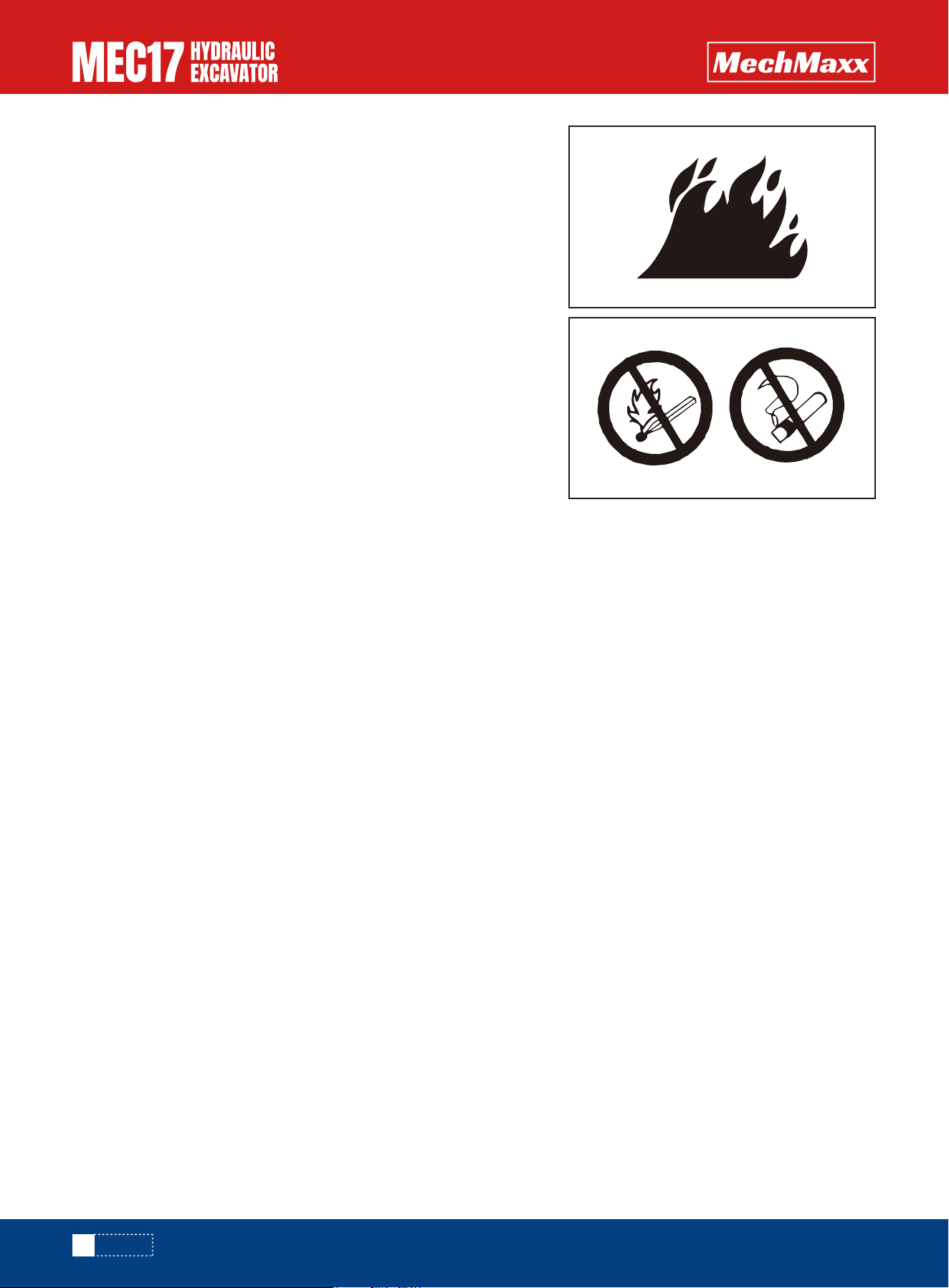
Fire prevention and Explosion Prevention Fire caused by fuel or oil.
Fire Caused by Accumulation of Flammable Material.
Fire coming from electric wiring
Fuel, oil, antifreeze, and window washer liquid are particularly flamma-
ble and can be hazardous. To prevent fire, always observe the following:
•Do not smoke or use any flame near fuel or oil.
•Stop the engine before refueling.
•Do not leave the machine while adding fuel or oil.
•Tighten all fuel and oil caps securely.
•Do not spill fuel on overheated surfaces or on parts of the electrical
system.
•Use well-ventilated areas for adding or storing oil and fuel.
•Keep oil and fuel in the determined place and do not allow unautho-
rized persons to enter.
•After adding fuel or oil, wipe up any spilled fuel or oil.
•When carrying out grinding or welding work on the machine, move any
flammable materials to a safe place before starting.
•When washing parts with oil, use a non-flammable oil. Diesel oil and
gasoline may catch fire, so do not use them.
•Put greasy rags and other flammable materials into a safe container
to maintain safety at the work place.
•Do not weld or use a cutting torch to cut any pipes or tubes that
contain flammable liquids.
Short circuits in the electrical system can cause fire.
•Always keep electric wiring connections clean and securely tightened.
•Check the wiring every day for looseness or damage. Tighten any loose connectors or wiring clamps. Repair or replace
any damaged wiring.
If fire occurs, escape from the machine as follows.
•Turn the start switch OFF to stop the engine.
•Use the handrails and steps to get off the machine.
Fire caused by piping
Check that all hoses and pipe clamps, shields and cushions are firmly fixed in place. If loosened, vibration and friction with
other parts will occur during operation, resulting in damage to hoses, high-pressure oil ejection, fire hazards or personal
accidents.
Explosion Caused by Lighting Equipment
Action in Case of Fire
•When checking fuel, oil, battery electrolyte, window washer fluid, or coolant, always use lighting with anti-explosion
specifications. If such lighting equipment is not used, there is danger of explosion that may cause serious injury.
•When taking the electrical power for the lighting from the machine itself, follow the instructions in this manual.
Remove any dry leaves, chips, pieces of paper, dust, or any other flammable materials accumulated or affixed around the
engine, exhaust manifold, muffler, or battery, or inside of the machine.
SAFETY
19
www.mechmaxx.com
•On jobsite there is a hazard that falling objects, flying objects, or
intruding objects may hit or enter the operator's cab, consider the
operating conditions and install the necessary guards to protect the
operator.
•When carrying out demolition or breaker operation, install a front
guard and use a laminated coating sheet on the front.
•When working in mines or quarries where there is a hazard of falling
rock, install FOPS (Falling Objects Protective Structure) and a front
guard, and use a laminated coating sheet on the front glass.
•When carrying out the above operations, always close the front
window. In addition, always ensure that standers-by are a safe
distance away and are not in hazard from falling or flying objects.
•The above recommendations assume that the conditions are for
standard operations, but it may be necessary to add additional guards
according to the operating conditions on the jobsite. Always contact
your Mechmaxx distributor for advice.
•When installing optional parts or attachments, there may be problems with safety or legal restrictions. Therefore
contact your mechmaxx distributor for advice.
•Any injuries, accidents, or product failures resulting from the use of unauthorized attachments or parts will not be the
responsibility of mechmaxx.
•When installing and using optional attachments, read the instruction manual for the attachment, and the general
information related to attachments in this manual.
Falling Objects, Flying Objects and Intruding Objects Prevention
Attachment Installation
Depending on the type or combination of work equipment, there is a hazard that the work equipment may hit the driving
shed or other parts of the machine.
Before using unfamiliar work equipment, check if there is any hazard of interference, and operate with caution.
Before starting operations, thoroughly check the area for any unusual
conditions that could be dangerous.
•When carrying out operations near combustible materials such as
thatched roofs, dry leaves or dry grass, there is a hazard of fire, so be
careful when operating.
•Check the terrain and condition of the ground at the jobsite, and deter-
mine the safest method of operation. Do not operate where there is a
hazard of landslides or falling rocks.
•If water lines, gas lines, or high-voltage electrical lines may be buried
under the job site, contact each utility and identify their locations. Be
careful not to sever or damage any of these lines.
•Any modification made without authorization from Mechmaxx may create hazards.
•Before making any changes, consult your authorized Mechmaxx distributor.
•Mechmaxx is not responsible for injuries, accidents, product failures, or property damage resulting from unauthorized
modifications.
Attachment Combinations
Unauthorized modifications
Safety on the Job site
SAFETY
20
www.mechmaxx.com
Prevent the machine tipping over
Distance to High Voltage Cables
•Take action to prevent unauthorized people from approaching the job site. When working on public roads, position
flagmen and erect barriers to ensure the safety of passing traffic and pedestrians.
•When traveling or operating in shallow water or on soft ground, check the shape and condition of the bedrock, and the
depth and speed of flow of the water before starting operations.
•Avoid traveling or operating your machine too close to the edge of cliffs, overhangs, and deep ditches. The ground may
be weak in such areas. If the ground should collapse under the weight or vibration of the machine, there is a hazard that
the machine may fall or tip over. Remember that the soil after heavy rain or blasting or after earthquakes is weak in
these areas.
•When working on embankments or near excavated ditches, there is a hazard that the weight and vibration of the
machine will cause the soil to collapse. Before starting operations, take steps to ensure that the ground is safe and to
prevent the machine from rolling over or falling.
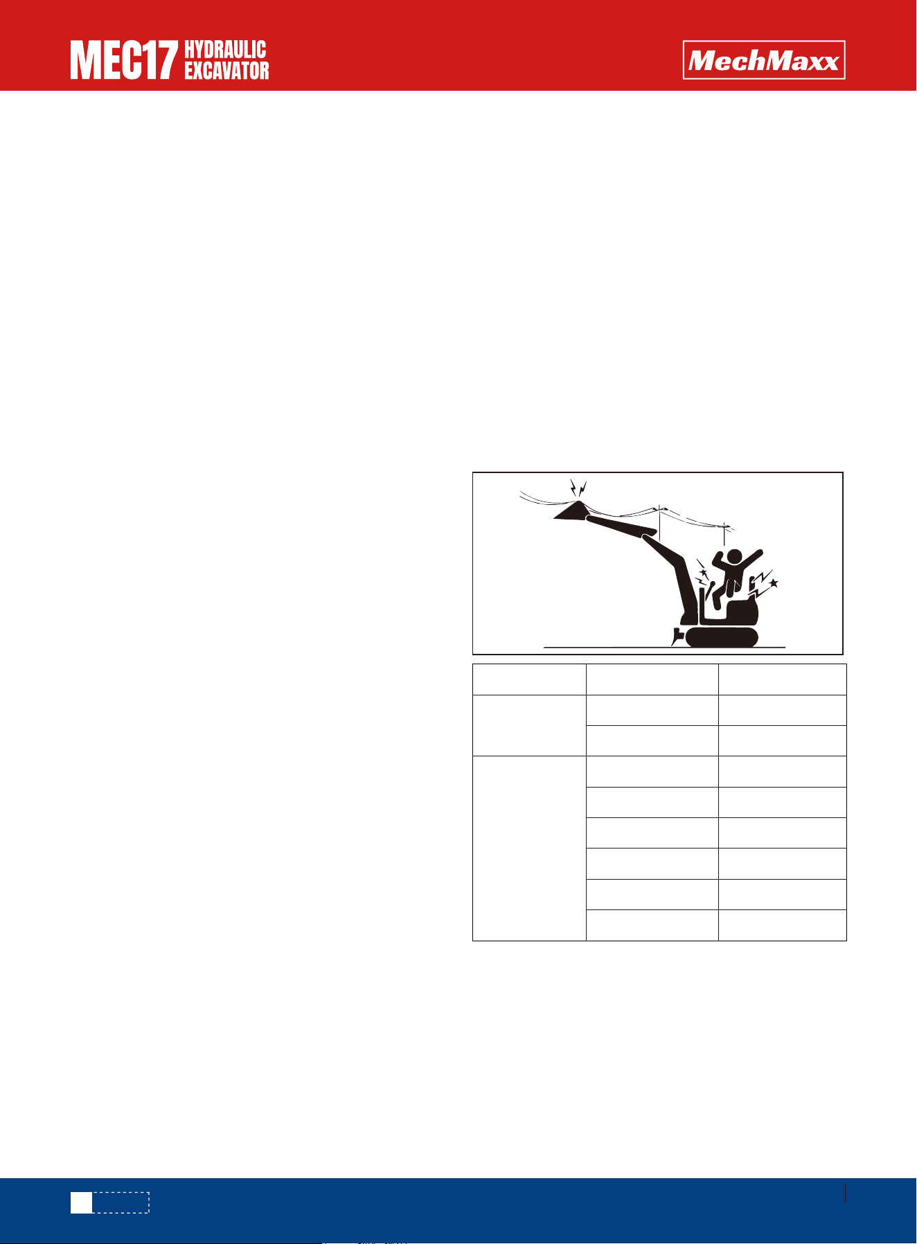
Do not travel or operate the machine near electric cables. There is a hazard of electric shock, which may cause serious
injury or property damage. On jobsites where the machine may go close to electric cables, always do as follows.
Ensure Good Visibility
Check for any persons or obstacles in the area around the machine and check the conditions of the job site to ensure that
operations and travel can be carried out safely. Always do as follows.
•When working in dark places, turn on the working lamp and front lamps installed to the machine, and set up additional
lighting in the work area if necessary.
•Stop operations if the visibility is poor, such as in mist, snow, rain, or dust.
•Before starting work near electric cables, inform the local
power company of the work to be performed, and ask them
to take the necessary action.
•Even going close to high-voltage cables can cause electric
shock. Always maintain a safe distance (see the table)
between the machine and the electric cable. Check with
the local power company about safe operating procedure
before starting operations.
•To prepare for any possible emergencies, wear rubber
shoes and gloves. Lay a rubber sheet on top of the seat,
and be careful not to touch the chassis with any exposed
part of your body.
•Use a signalman to give warning if the machine approaches
too close to the electric cables.
•When carrying out operations near high voltage cables, do
not let anyone near the machine.
•If the machine should come too close or touch the electric
cable, to prevent electric shock, the operator should not
leave the operator's compartment until it has been
confirmed that the electricity has been shut off. Also, do
not let anyone near the machine.
Safety DistanceVoltage of Cables
Low voltage
Extra high
voltage
100 V-200 V
6600 V
22000 V
66000 V
154000 V
187000 V
275000 V
500000 V
Over 2 m (7 ft)
Over 2 m (7 ft)
Over 3 m (10 ft)
Over 4 m (14 ft)
Over 5 m (17 ft)
Over 6 m (20 ft)
Over 7 m (23 ft)
Over 11 m (36 ft)
SAFETY

21
www.mechmaxx.com
Ventilation for Enclosed Area
If it is necessary to start the engine within an enclosed area, or when handling
fuel, flushing oil, or paint, open the doors and windows to ensure that adequate
ventilation is provided to prevent gas poisoning.
Signalman's Signal and Signs
Asbestos Dust Hazard Prevention
•Set up signs to inform of road shoulders and soft ground. If the visibility is not good, position a signalman if necessary.
Operators should pay careful attention to the signs and follow the instructions from the signalman.
•Only one signalman should give signals.
•Make sure that all workers understand the meaning of all signals and signs before starting work.
Asbestos dust in the air can cause lung cancer if it is inhaled. There is danger of
inhaling asbestos when working on job sites handling demolition work or work
handling industrial waste. Always observe the following.
•Spray water to keep down the dust when cleaning. Do not use compressed air for
cleaning.
•If there is danger that there may be asbestos dust in the air, always operate the
machine from an upwind position. All workers should use an approved respirator.
•All personnel should use dust masks.
•Do not allow other persons to approach during the operation.
•Always observe the rules and regulations for the work site and environmental
standards.
•This machine does not use asbestos, but there is a danger that imitation parts
may contain asbestos, so always use genuine mechmaxx parts.
SAFETY

22
www.mechmaxx.com
Safety Machine Operation
Starting Engine
Checks before Starting Engine
Safety rules for Starting Engine
Starting Engine in Cold Weather
If there is a warning tag hanging from the work equipment control lever, do not
start the engine or touch the levers .
Carry out the following checks before starting the engine at the beginning of the day's work.
•Remove all dirt from the surface of the window glass to ensure a good view.
•Remove all dirt from the surface of the lens of the working lamps, and check that they light up correctly.
•Check the coolant level, fuel level, and oil level in engine oil pan, check for clogging of the air cleaner, and check for
damage to the electric wiring.
•Adjust the operator's seat to a position where it is easy to carry out operations, and check that there is no damage or
wear to the seat belt or mounting clamps.
•Check the operation of the instruments and gauges, check the angle of the mirror, and check that the control levers are
all at the Neutral position.
•Before starting the engine, check that lock lever is in LOCK position.
•Check that there are no persons or obstacles above, below, or in the area around the machine.
•Start and operate the machine only while seated.
•Do not attempt to start the engine by short-circuiting the engine starting circuit. Such an act may cause a serious bodily
injury or fire.
•When starting the engine, sound the speaking as a warning.
•Do not allow anyone apart from the operator to ride on the machine.
•Carry out the warming-up operation thoroughly. If the machine is not thoroughly warmed up before the control levers or
control pedals are operated, the reaction of the machine will be slow or the machine may move in a way not expected
by the operator.
•If the battery electrolyte is frozen, do not charge the battery or start the engine with a different power source. There is
a hazard that this will ignite the battery and cause the battery to explode.
•Before charging or starting the engine with a different power source, melt the battery electrolyte and check that there
is no leakage of electrolyte before starting.
SAFETY
23
www.mechmaxx.com
Operation
Checks before Operation
Safety Rules for Changing Machine Directions
Safety Rules for Traveling
When carrying out the checks, move the machine to a wide area where there are no obstructions, and operate slowly. Do
not allow anyone near the machine.
•Always fasten your seat belt.
•Check that the movement of the machine matches the display on the control pattern card. If it does not match, replace
it immediately with the correct control pattern card.
•Check the operation of the gauges and equipment, and check the operation of the bucket, arm, boom, travel system,
swing system, and steering system.
•Check for any problem in the sound of the machine, vibration, heat, smell, or gauges; check that whether there is
leakage of oil or fuel or not.
•If any problem is found, carry out repairs immediately.
Before traveling, set the machine so that sprocket ① is behind the operator's
seat. If sprocket ① is in front of the operator's seat, the machine is in the opposite
direction from the operation of the lever(front and rear travel is reversed, left and
right steering is reversed). Be extremely careful when operating the machine in this
situation.
•Before traveling, check again that there is no one in the surrounding area, and that
there are no obstacles.
•Before traveling, sound the speaker to warn people in the area.
•Always operate the machine only when seated.
•Do not allow anyone apart from the operator to ride on the machine.
•If there is an area to the rear of the machine which cannot be seen, position a
signal person. Take special care so as not to hit other machines or people when
turning or swinging the machine.
•Check that the travel alarm (optional) works properly.
Always be sure to carry out the above precautions even when the machine is
equipped with mirrors.
•Do not operate the machine at excessive speed, or start, stop, or turn suddenly.
•On flat ground, keep the work equipment 1.57–1.97 in (40–50 mm) above the
ground.
•On rough ground, travel slowly and avoid sudden steering. Sudden movements
may cause the machine to tip over, strike the ground, or damage nearby struc-
tures.
•Avoid traveling over obstacles whenever possible. If crossing is unavoidable, keep
the work
1
1.57-1.97 in
SAFETY
Operations on Slopes
Prohibited Operations
•When working on slopes, there is a hazard that the machine
may lose its balance and turn over when the swing or work
equipment are operated. This may lead to serious injury or
property damage, so always provide a stable place when carry-
ing out these operations, and operate carefully.
•Do not swing the work equipment from the uphill side to the
downhill side when the bucket is loaded. This operation is
dangerous, and may cause the machine to tip over.
•If the machine has to be used on a slope, pile the soil to make
a platform (A) that will keep the machine as horizontal as
possible.
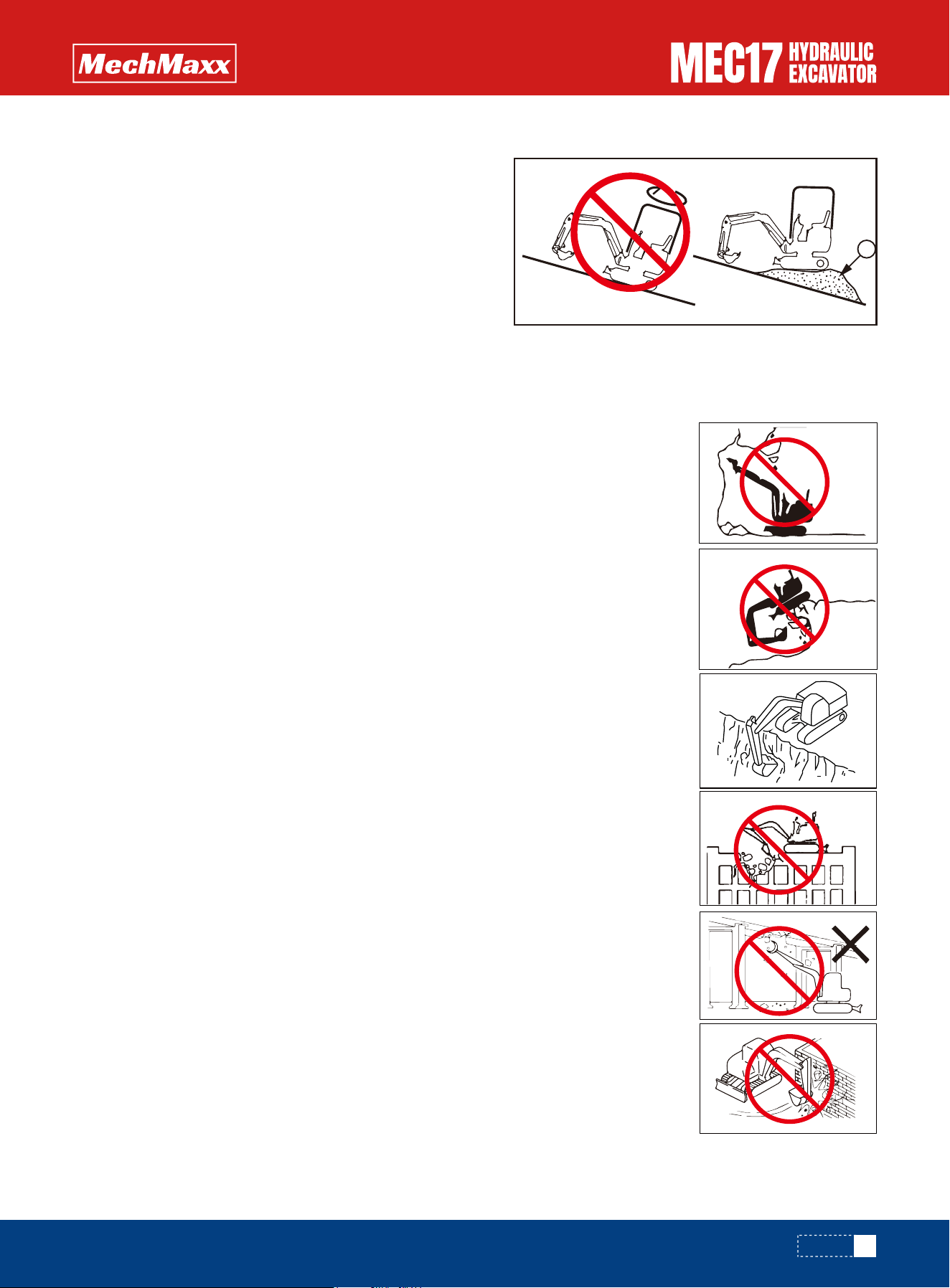
•Never dig the work face under an overhang. There is a hazard that rocks may fall or that the
overhang may collapse and fall on top of the machine.
•Do not excavate too deeply under the front of the machine. The ground under the machine
may collapse and cause the machine to fall.
•To make it easier to escape if there is any problem, set the tracks at right angles to the
road shoulder or cliff with the sprocket at the rear when carrying out operations.
•Do not carry out demolition work under the machine. There is a hazard that the machine
may become unstable and tip over.
•When working on or from the top of buildings or other structures, check the strength and
the structure before starting operations. There is a hazard of the building collapsing and
causing serious injury or damage.
•When carrying out demolition work, do not carry out demolition above your head. There is a
hazard of broken parts falling or of the building collapsing and causing serious injury or
property damage.
•Do not use the impact force of the work equipment for breaking work. There is a hazard of
damage to the work equipment, or a hazard of serious personal injury being caused by
flying pieces of broken materials, or of the machine tipping over due to reaction from the
impact.
•Generally speaking, the machine is more liable to overturn when the work equipment is at
the side than when it is at the front or rear.
•When using a breaker or other heavy work equipment, there is a hazard of the machine
losing its balance and tipping over. When operating on flat ground as well as on slopes.
•Do not suddenly lower, swing, or stop the work equipment.
•Do not suddenly extend or retract the boom cylinder. There is a hazard that impact will
cause the machine to tip over.
•Do not pass the bucket over the head of other workers or over the operator's seat of dump
trucks or other hauling equipment. The load may spill or the bucket may hit the dump truck
and cause serious injury or property damage.
25
www.mechmaxx.com
A
SAFETY
24
www.mechmaxx.com
Traveling on Slopes
•When traveling or carrying out operations, always keep a safe distance from
people, structures, or other machines to avoid coming into contact with them.
•When crossing bridges or structures, first confirm that they are strong enough to
support the machine’s weight.
•When traveling on public roads or highways, contact the relevant authorities in
advance and follow their instructions.
•When operating in tunnels, under bridges, under electric wires, or other places
where the height is limited, operate slowly and be extremely careful not to let the
work equipment hit anything.
•Do not let the machine or working device touch anything.
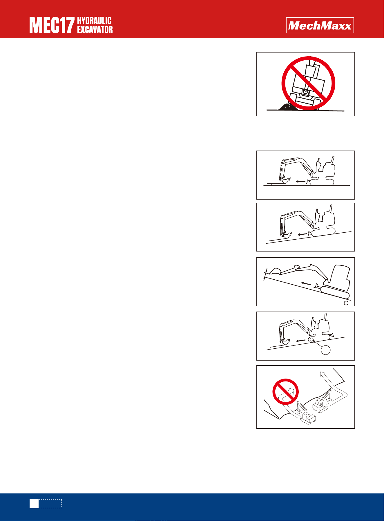
To prevent the machine from tipping over or slipping to the side, always do as
follows.
•Keep the work equipment approx. 0.7 to 1.1 in above the ground. In case of emer-
gency, lower the work equipment to the ground immediately to help stop the
machine.
•When traveling up slopes, set the driver's shed facing uphill, when travel down
slopes, set the driver's shed facing downhill. Always check the firmness of the
ground under the front of the machine when traveling.
•When traveling up a steep slope, extend the work equipment to the front to
improve the balance, keep the work equipment approximately 0.7 to 1.1 in above
the ground, and travel at low speed.
•When traveling downhill, lower the engine speed, keep the travel lever close to the
neutral position, and travel at low speed.When walking downhill on a slope with a
slope of 15°or more, as shown in the right figure, place the driving wheel ① on
the downhill side, reduce the engine speed and walk.
•Always travel straight up or down a slope. Traveling at an angle or across the
slope is extremely dangerous.
•Do not turn on slopes or travel across slopes. Always go down to a flat place to
change the position of the machine, then travel on to the slope again.
•Travel on grass, fallen leaves, or wet steel plates with low speed. Even with slight
slopes there is a hazard that the machine may slip.
•If the engine stops when the machine is traveling on a slope, move the control
levers immediately to the neutral position and start the engine again.
0.7 to 1.1 in
0.7 to 1.1 in
0.7 to 1.1 in
0.7 to 1.1 in
1
SAFETY
Operations on Snow
Parking Machine
•Snow-covered or frozen surfaces are slippery, so be extremely careful when traveling or operating the machine, and do
not operate the levers suddenly. Even a slight slope may cause the machine to slip, so be particularly careful when work-
ing on slopes.
•With frozen ground surfaces, the ground becomes soft when the temperature rises, and this may cause the machine to
tip over.
•If the machine enters deep snow, there is a hazard that it may tip over or become buried in the snow. Be careful not to
leave the road shoulder or to get trapped in a snow drift.
•When clearing snow, the road shoulder and objects placed beside the road are buried in the snow and cannot be seen.
There is a hazard of the machine tipping over or hitting covered objects, so always carry out operations carefully.
•Park the machine on firm, level ground.
•Select a place where there is no hazard of falling rocks or landslides, or of
flooding if the land is low.
•Lower the work equipment completely to the ground.
•When leaving the machine, set lock lever to the LOCK position, then stop
the engine.
•Always close the operator's cab door, and use the key to lock all the equip-
ment in order to prevent any unauthorized person from moving the machine.
Always remove the key, take it with you, and leave it in the specified place.
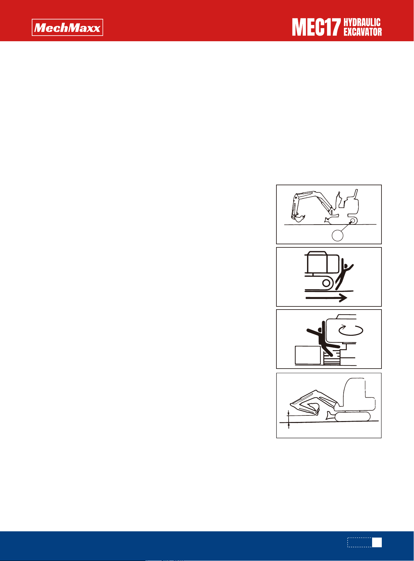
•If it is necessary to park the machine on a slope, always do as follows.
• Set the bucket on the downhill side, then dig it into the ground.
• Put blocks under the tracks to prevent the machine from moving.
26
www.mechmaxx.com
120°
SAFETY
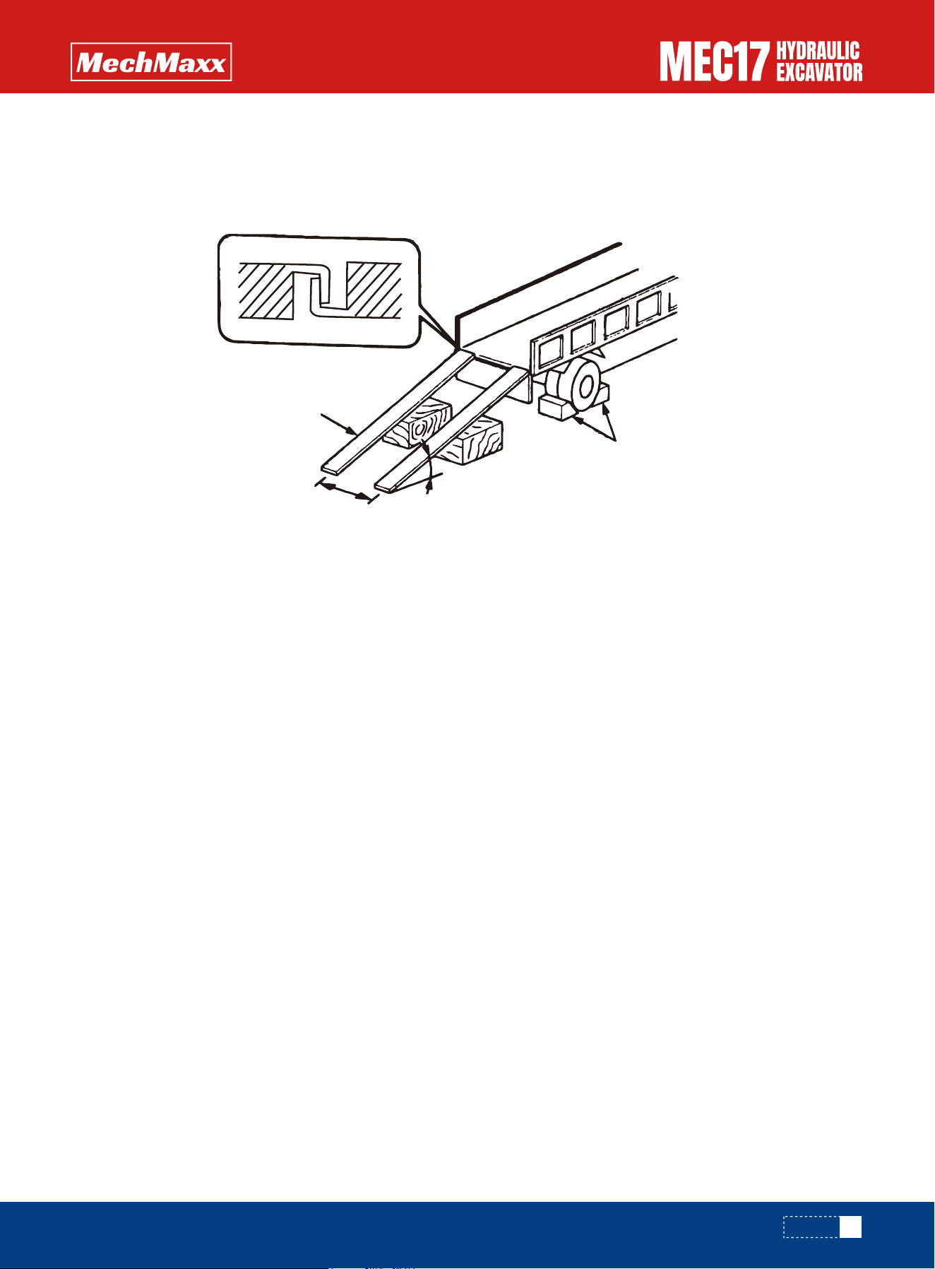
Loading and Unloading
Shipping the Machine
When loading or unloading the machine, mistaken operation may bring the hazard of the machine tipping over or falling,
so particular care is necessary. Always do as follows.
•Choose a solid and flat ground and keep a safe distance from the shoulders and edges of the road. Never use working
devices to load and unload machines. Otherwise, there is a danger of the machine tipping or falling.
•Always use ramps of adequate strength. Be sure that the ramps are wide, long, and thick enough to provide a safe
loading slope. Take suitable steps to prevent the ramps from moving out of position or coming off. Be sure the ramp
surface is clean and free of grease, oil, ice and loose materials. Remove dirt from machine-tracks. On a rainy day, in
particular, be extremely careful since the ramp surface is slippery.
•Run the engine at low speed and travel slowly.
•Never correct your steering on the ramps. If necessary, drive off the ramps, correct the direction, then enter the ramps
again.
•When on the ramps, do not operate any lever except for the travel lever.
•The center of gravity of the machine will change suddenly at the joint between the ramps and the track or trailer, and
there is danger of the machine losing its balance. Travel slowly over this point.
•When loading or unloading to an embankment or platform, make sure that it has suitable width, strength, and grade.
•When swinging the upper structure on the trailer, the trailer is unstable, so pull in the work equipment and swing slowly.
•Refer to “Transportation”.
When transporting the machine on a trailer, follow these instructions:
•The machine’s weight, transport height, and overall length vary depending on the work equipment installed. Always
confirm the actual dimensions before transport.
•When crossing bridges or structures on private property, first ensure that they are strong enough to support the
machine’s weight.
•When traveling on public roads, consult the relevant authorities in advance and follow their instructions.
•For detailed transport procedures, refer to the “Transportation” section.
①Stoppers ②Ramp ③Spacing of ramp ④The ramp angle is under 15° ⑤Blocks
27
www.mechmaxx.com
Transport
1
2
3
4
5
SAFETY
Battery
Put the Battery cut-off Switch OFF (closed)
Battery Safety Operation
For the following occasions, puts starting switch OFF (closed) position, put the battery cut-off switch OFF (closed)
position. Otherwise may cause electric shock and other major accidents.
•Long term storage machine (more than one month);
•When repairing the electrical system;
•When welding;
•When handling the battery;
•When replacing fuses and other parts.
Electricity
•When battery positive and negative electrodes on both ends of a column by metal conductor (such as: metal tools,
metal wire, metal parts, etc.) accident nipple, namely external battery short circuit, can produce arc melting polar
column, and cause the molten lead alloy splash, serious when the combustion caused a lot of heat.
•Prevention: battery assembly fault diagnosis using metal tools or use metal wire, avoid direct short circuit battery is
negative column.
•Protection: wear protective glasses and gloves.
•Emergency treatment: when burning, use live wrench or other tools, external short-circuit metal conductor, immediately
disconnect the battery don't contact with, and use the extinguishing fire materials.
Sulfuric Acid
•Filling battery or a battery charging, resulting in shell burst, from sulphuric acid
may break out or spills.
•Prevention: careful handling. Vertical placement; According to the supplementa-
ry electrical program to supplement the electricity.
•Protection: wear protective glasses and acid proof clothes.
•Emergency treatment: when skin contact with sulfuric acid, immediately flush
skin with plenty of clean flowing water surface, and remove contaminated
clothes; When the eyes contact with sulfuric acid, rinse immediately with clean
water for at least 10 minutes; When due to accidentally splashed acid in the
mouth, can drink lots of water or milk. To find a doctor when necessary.
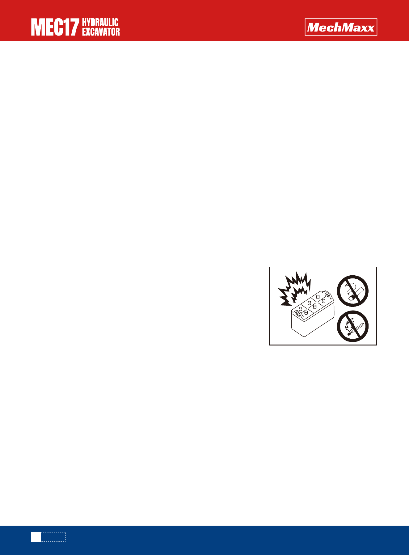
Emissions of Gases
•In rechargeable battery, test process, the mixture of hydrogen and oxygen from the induction in vent. If more than 4%
hydrogen concentration in the environment, have open flame, sparks or high fever will be an explosion.
•Prevention: charging keep ventilation. Smoking is prohibited, to prevent sparks and open flame. Battery wire connection
order: first the positive line connection, after connect the cathode lines; Disconnect the battery cable order: first to
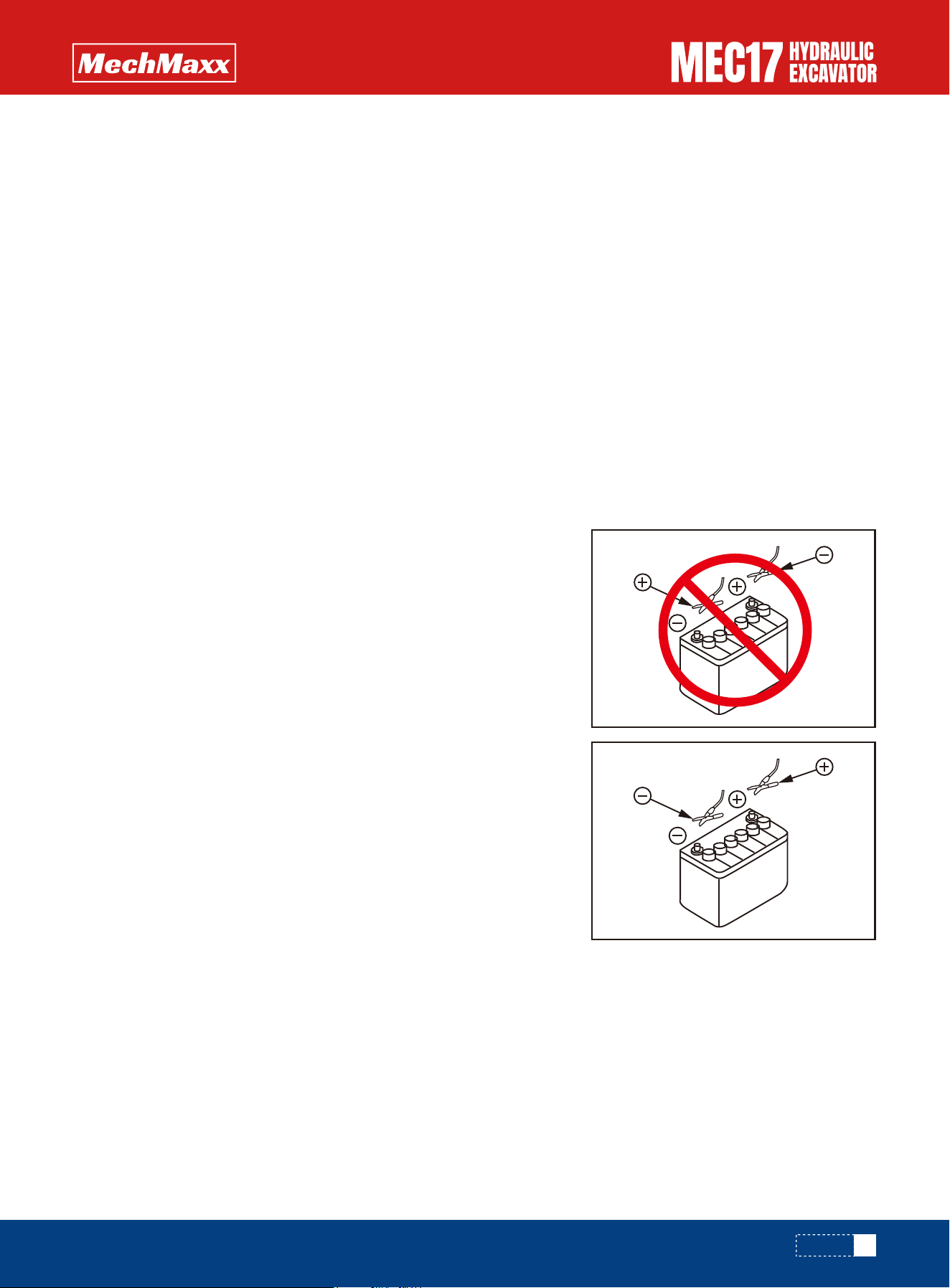
disconnect the battery negative electrode wire, and then disconnect the battery positive electrode line.
•Protection: wear protective glasses and acid proof clothes.
•Emergency treatment: battery burst, a large number of spills, sulfate operator should immediately flush sulfuric acid
splash down; When necessary, will be ablation of sulfate personnel immediately to a hospital treatment.
28
www.mechmaxx.com
SAFETY
Additional Electric Battery
Staring Engine with Booster Cables
Before cars started, the car with electric start time is too long and abnormal use, because of leakage and long car stops,
the vehicle or the vehicle charging generator failure, the battery can't normal charging battery loss caused by electricity,
battery electric eye blackened, even can't start the car. The battery need to supplement by electricity.
Check that the open circuit voltage of the battery terminal is lower than 12.45V, and the battery should be supplemented
immediately.
If any mistake is made in the method of connecting the booster cables, it may cause the battery to explode, so always do
as follows.
•When starting with a booster cable, carry out the starting operation with
two workers (one worker sitting in the operator's seat and the other work-
ing with the battery).
•When starting from another machine, do not allow the two machines to
touch.
•When connecting the booster cables, turn the starting switch OFF for both
the normal machine and problem machine. There is a hazard that the
machine will move when the power is connected.
•Be sure to connect the positive (+) cable first when installing the booster
cables. Disconnect the negative (-) cable (ground side) first when remov-
ing them.
•When connecting the auxiliary cable, set the start switch of the faulty
machine, the battery disconnect switch and the start switch of the normal
machine to the OFF (closed) position. For details, please refer to the item
"Battery disconnect switch". When the power is connected, the machine
may start and cause danger.
•When removing the booster cables, be careful not to let the booster cable
clips touch each other or to let the clips touch the machine.
•Always wear safety goggles and rubber gloves when starting the engine
with booster cables.
•When connecting a normal machine to a problem machine with booster
cables, always use a normal machine with the same battery voltage as the
problem machine.
•For details of the starting procedure when using booster cables, see
“Starting Engine with Booster Cables” in the OPERATION section.
When charging the battery we must know
•Wearing glasses.
•Maintain environmental ventilation when charging, charging under normal temperature.
•No smoking when charging, and to avoid the introduction of the flame.
•After charging connection, first connect the positive attachment; Take out stitches before charging, disconnect the
cathode attachment first.
Battery supplement electricity at action part “Battery Discharges and Charges”.
29
www.mechmaxx.com
SAFETY
Towing and Being Towed
Lifting Work
Safety Rules for Towing and Being Towed
Safety Rules for Lifting Objects
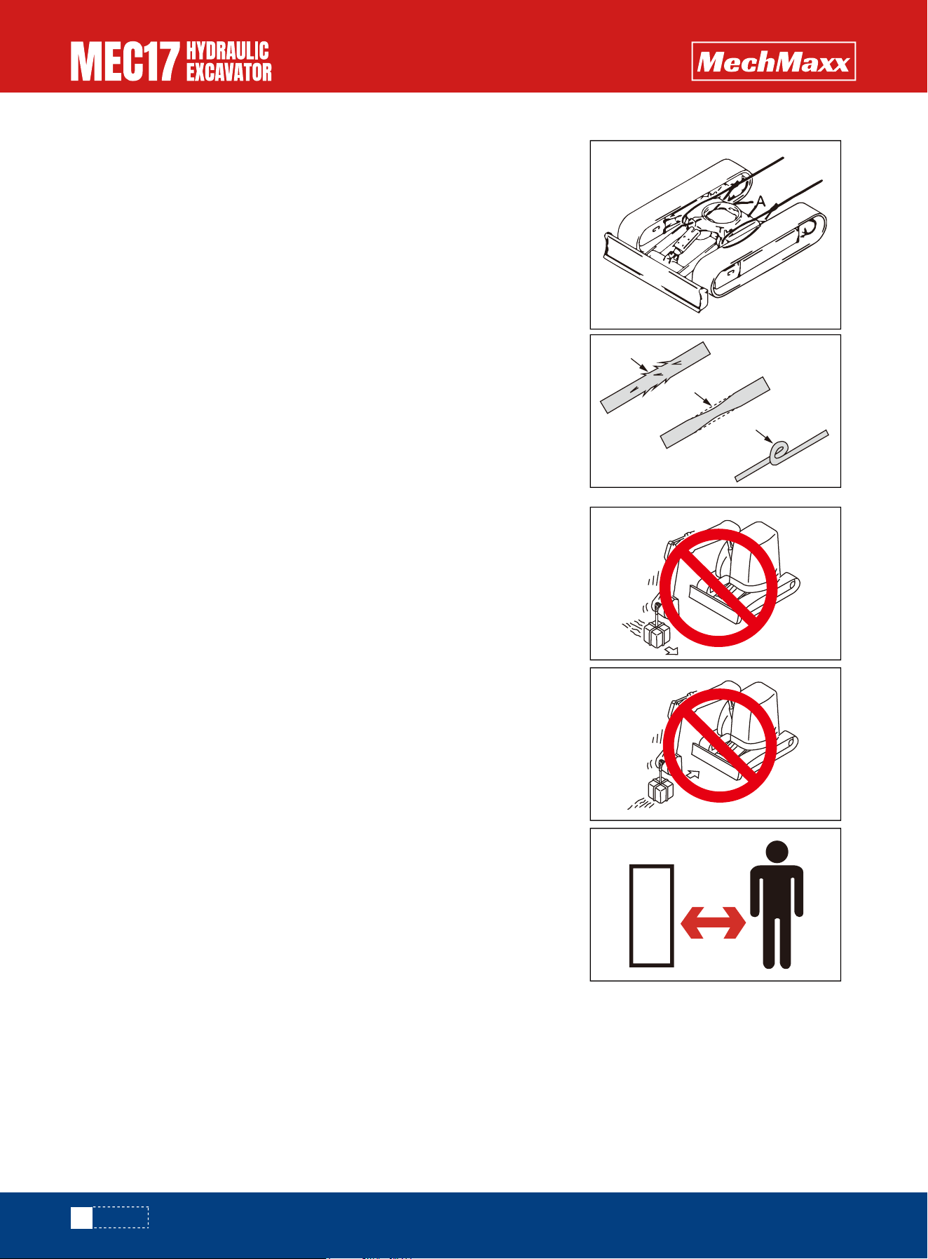
Serious injury or death could result if a disabled machine is towed incorrectly
or if there is a mistake in the selection or inspection of the wire rope. For
towing, see “Towing the Machine” in the OPERATION section.
•Always wear leather gloves when handling wire rope.
•Fix the wire rope to the frame of the crawler frame (allow two holes at A for
traction)
•During the towing operation, never stand between the towing machine and
the machine being towed.
•Never tow a machine on a slope.
•Never use a wire rope which has cut strands (A), reduced diameter (B), or
kinks (C). There is danger that the rope may break during the towing opera-
tion.
•Do not carry out lifting work on slopes, soft ground, or other places where the
machine is not stable.
•Use wire rope that conforms to the specified standard.
•Do not exceed the specified lifting load.
•For details of the maximum lifting load permitted for this machine, see
“Bucket with hook”.
•It is dangerous if the load hits any worker or structure. Always check carefully
that the surrounding area is safe before swinging or turning the machine.
•Do not start, swing, or stop the machine suddenly. There is a hazard that the
lifted load will swing.
•Don't use two machines together to lift, it is very dangerous.
•Do not use the work equipment or swing to pull the load in any direction. There
is danger that the hook may break and the load come off, causing the work
equipment to move suddenly and cause personal injury.
•Do not leave the operator's seat when there is a raised load.
•Do not pull pile.
30
www.mechmaxx.com
A
B
C
SAFETY
Safety Maintenance Information
Warning Tag
Keep Work Place Clean and Tidy
•Always attach the "DO NOT OPERATE" warning tag to the work equipment
control lever. Attach additional warning tags around the machine if neces-
sary.
•Keep this warning tag in the tool box while it is not used. If there is not the
tool box, keep the tag in the operation manual pocket.
•If others start the engine, or touch or operate the work equipment control
lever while you are performing service or maintenance, you could suffer
serious injury or property damage.
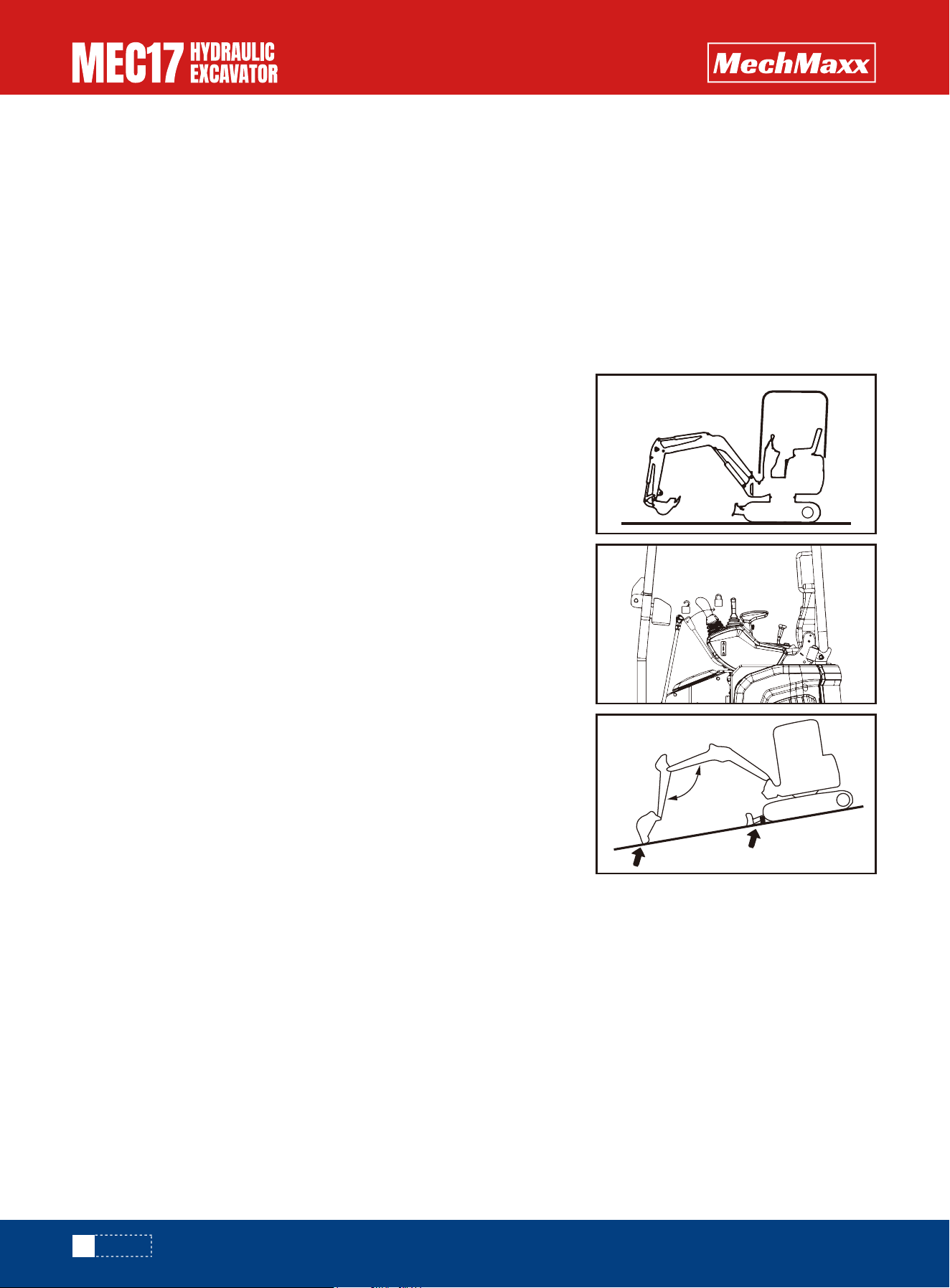
•Choose a flat and solid place.
•Choose a place where there is no danger of landslides, falling rocks or
being flooded.
•Make the working device and the bulldozer fully contact the ground.
•Park the machine on firm, level ground.
•Select a place where there is no hazard of falling rocks or landslides, or of
flooding if the land is low.
•Lower the work equipment and Bulldozer completely to the ground.
•Check that the battery relay is off and main power is not conducted. (Wait for
approx one minute after turning off the engine starting switch key and press
the horn switch. If the horn does not sound, it is not activated.)
•Push up the work equipment control lever to middle position and push up lock
lever to the LOCK position, then turn off the engine.
•Put blocks under the track to prevent the machine from moving.
Appoint Leader When Working with Others
Turn off the Engine before Checking and Maintenance
When repairing the machine or when removing and installing the work equipment, appoint a leader and follow his instruc-
tions during the operation.
When working with other people, if the meaning is conveyed incorrectly between the workers, it will cause accidents.
31
www.mechmaxx.com
SAFETY
Two workers for maintenance when engine is running
Proper tools
To prevent injury, do not carry out maintenance with the engine running. If
maintenance must be carried out with the engine running, carry out the
operation with at least two workers and do as follows.
•One worker must always sit in the operator's seat and be ready to stop the
engine at any time. All workers must maintain contact with the other
workers.
•Set lock lever to the LOCK position (L).
•When carrying out operations near the fan, fan belt, or other rotating parts,
there is a hazard of being caught in the parts, so be careful not to come
close.
•Do not touch any control levers. If any control lever must be operated, give
a signal to the other workers to warn them to move to a safe place.
•Never drop or insert tools or other objects into the fan or fan belt. Parts
may break or be sent flying.
Use only tools suited to the task and be sure to use the tools correctly.
Using damaged, low quality, faulty, makeshift tools or improper use of the
tools could cause serious personal injury.
Personnel
Only authorized personnel can service and repair the machine. Do not allow unauthorized personnel into the area. If neces-
sary, employ an observer.
Attachment
•Appoint a leader before starting removal or installation operations for
attachments.
•Place attachments that have been removed from the machine in a stable
condition so that they do not fall. And take steps to prevent unauthorized
persons from entering the storage area.
Work under the machine
Noise
•If you must go under the work equipment or machine for service or maintenance, always support them securely with
blocks and stands strong enough to bear their weight.
•Never rely on the work equipment alone for support. If the track shoes are off the ground and the machine is supported
only by the work equipment, accidental movement of the control levers or hydraulic failure may cause it to drop suddenly.
•Never work under unsupported equipment or the machine—this is extremely dangerous and may result in serious injury
or death.
When carrying out maintenance of the engine and you are exposed to noise for long periods of time, wear ear covers or
ear plugs while working. If the noise from the machine is too loud, it may cause temporary or permanent hearing problems.
32
www.mechmaxx.com
SAFETY
Hammer
When striking hard metal parts such as pins, bucket teeth, cutting edges, or
bearings, metal fragments may scatter and cause serious injury.
•Always wear protective equipment such as goggles and gloves.
•Ensure no one is in the surrounding area before striking pins or bucket teeth
to prevent injury from flying fragments.
•Do not strike pins with excessive force. Overstriking may cause the pin to fly
out and injure people nearby.
Welding works
Welding operations must always be carried out by a qualified welder and in a place equipped with proper equipment. There
is a hazard of gas, fire, or electrocution when carrying out welding, so never allow any unqualified personnel to carry out
welding.
Removing battery terminals
When repairing the electrical system or when carrying out electrical welding, remove the negative (-) terminal of the
battery to prevent the flow of current.
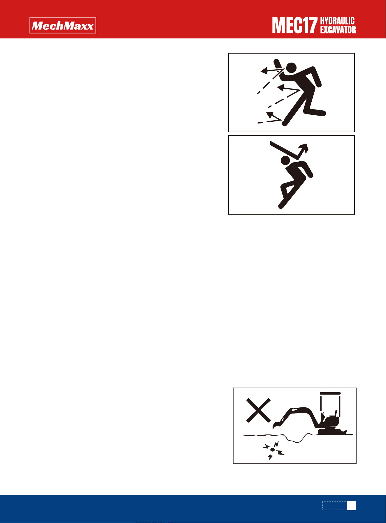
Safety first when using high-pressure grease to adjust track tension
Do not disassemble recoil springs
•Grease is pumped into the track tension adjustment system under high
pressure. If the specified procedure for maintenance is not followed when
making adjustment, grease drain plug (1) may fly out and cause serious injury
or property damage.
•When loosening grease drain plug (1) to loosen the track tension, never
loosen it more than one turn. Loosen the grease drain plug slowly.
•Do not place the face, hands, feet or other parts of the body close to the
grease drain plug①.
Never attempt to disassemble the recoils spring assembly. It contains a spring
under high pressure which serves as a shock absorber for the idler. If it is
disassembled by mistake, the spring will fly out and cause serious injury. When
it becomes necessary to disassemble it, ask your mechmaxx distributor to do
the work.
High pressure oil
Hydraulic system is stressful .When inspecting or replacing the pipe or hose, be sure to check the pressure inside the
hydraulic circuit has been released, otherwise, it will cause major accidents. So do as the following provisions:
•Release the pressure. When the hydraulic system has pressure, don't inspect
and replace the operation.
•If there are any pipe or hose leaks, or its surrounding area is wet, check
whether the pipe or hose burst, and whether the hose expansion. Wear
protective equipment such as goggles and leather gloves, when check.
•High pressure oil from the hole leakage will penetrate into the skin, if it
contact with eyes direction, you will be at the risk of blindness. If skin or eyes
was hit by a high pressure oil, Rinse with clean water and contact the doctor
immediately.
33
www.mechmaxx.com
1
SAFETY
If high pressure hose or pipeline leak, it will cause a fire or the operation failure, lead to major accidents. If you find the
hose leaks or the installation of piping parts loose, stop working and tighten the installation site to specified torque
again. If there is any damage on hose or piping or deformation, contact with the mechmaxx distributor.
Operation of the pipeline and high pressure hose
Waste materials
The hose should be replaced, if existence as follows:
•Hose damage, pipe joint deformation, o-ring damage.
•Cladding torn or broken, or reinforcing steel wire exposed.
•Clad inflation in some places.
•Movable part of the hose distorted or signs of a crush.
•Cladding with foreign matter.
To prevent pollution, pay careful attention to the method of disposing of waste
materials.
•Always put oil drained from your machine in containers. Never drain oil directly
onto the ground or dump into the sewage system, rivers, the sea, or lakes.
•Obey appropriate laws and regulations when disposing of harmful objects
such as oil, fuel, coolant, solvent, filters, and batteries.
Compressed air
•When carrying out cleaning with compressed air, there is a hazard of serious injury caused by flying particles.
•When using compressed air to clean elements or the radiator, always wear safety goggles, dust mask, gloves, and other
protective equipment.
Periodic replacement of safety critical parts
•For using the machine safely for an extended period of time, replace safety-critical parts like hoses and seat belts
periodically. Replacement of safety-critical parts: See “Safety Critical Parts”.
•The material of these components naturally changes over time, and repeated use causes deterioration, wear, and
fatigue. As a result, there is a hazard that these components may fail and cause serious injury or death. It is difficult to
judge the remaining life of these components from external inspection or the feeling when operating, so always replace
them at the specified interval.
•Replace or repair safety-critical parts if any defect is found, even when they have not reached the time specified interval.
34
www.mechmaxx.com
SAFETY
OPERATION
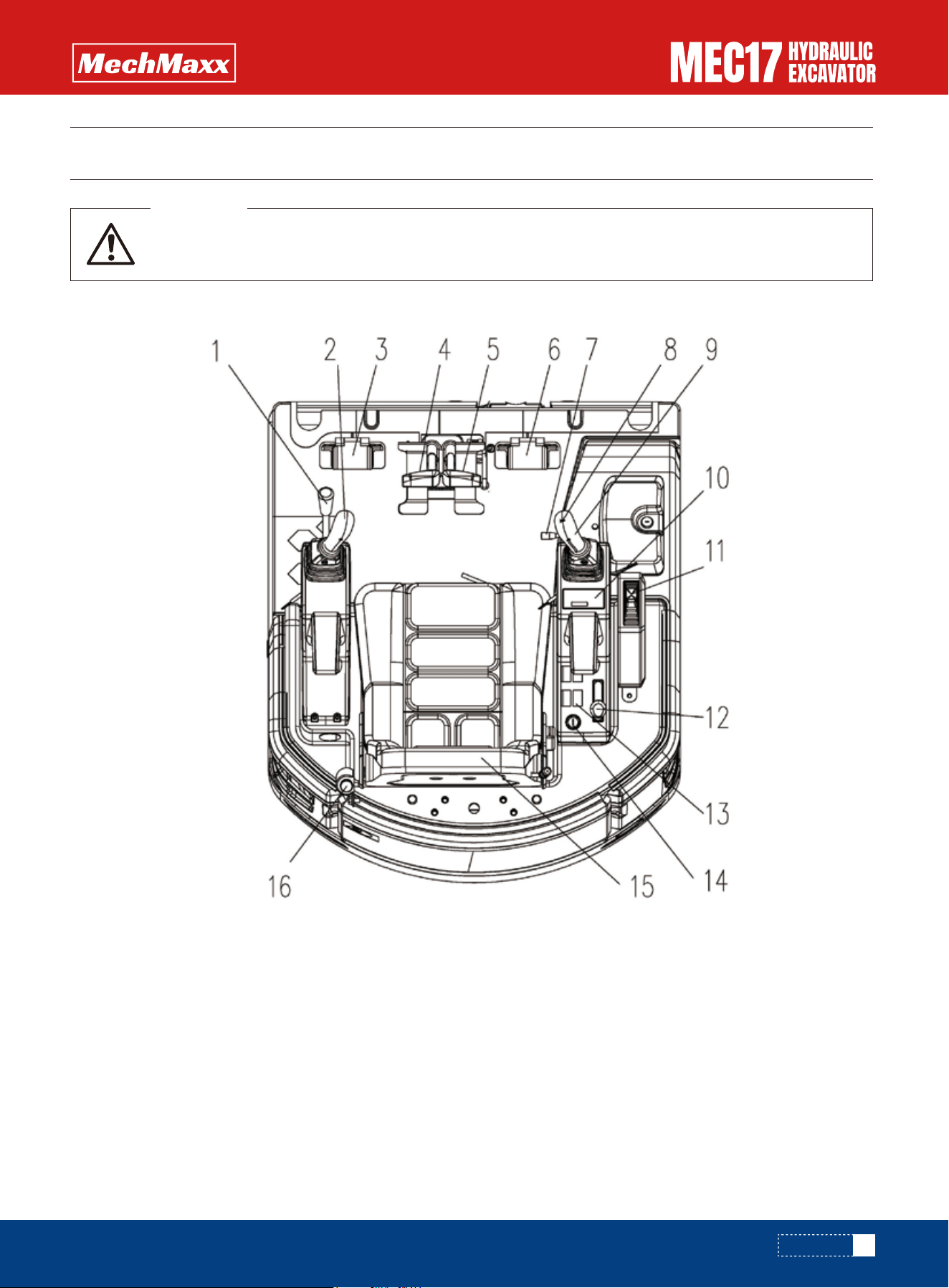
General Drawing of Control Device
1. Security lock lever
2. Left working device joystick
3. Auxiliary pipeline control
4. Left walking joystick
5. Right walking joystick
6. Boom side swing control
7. Bulldozing and under frame luffing switching operation
8. Speaker switche specified interval.
9. Right working device joystick
10.Monitor
11.Bulldozer control handle
12.Throttle joystick
13.Shift switch
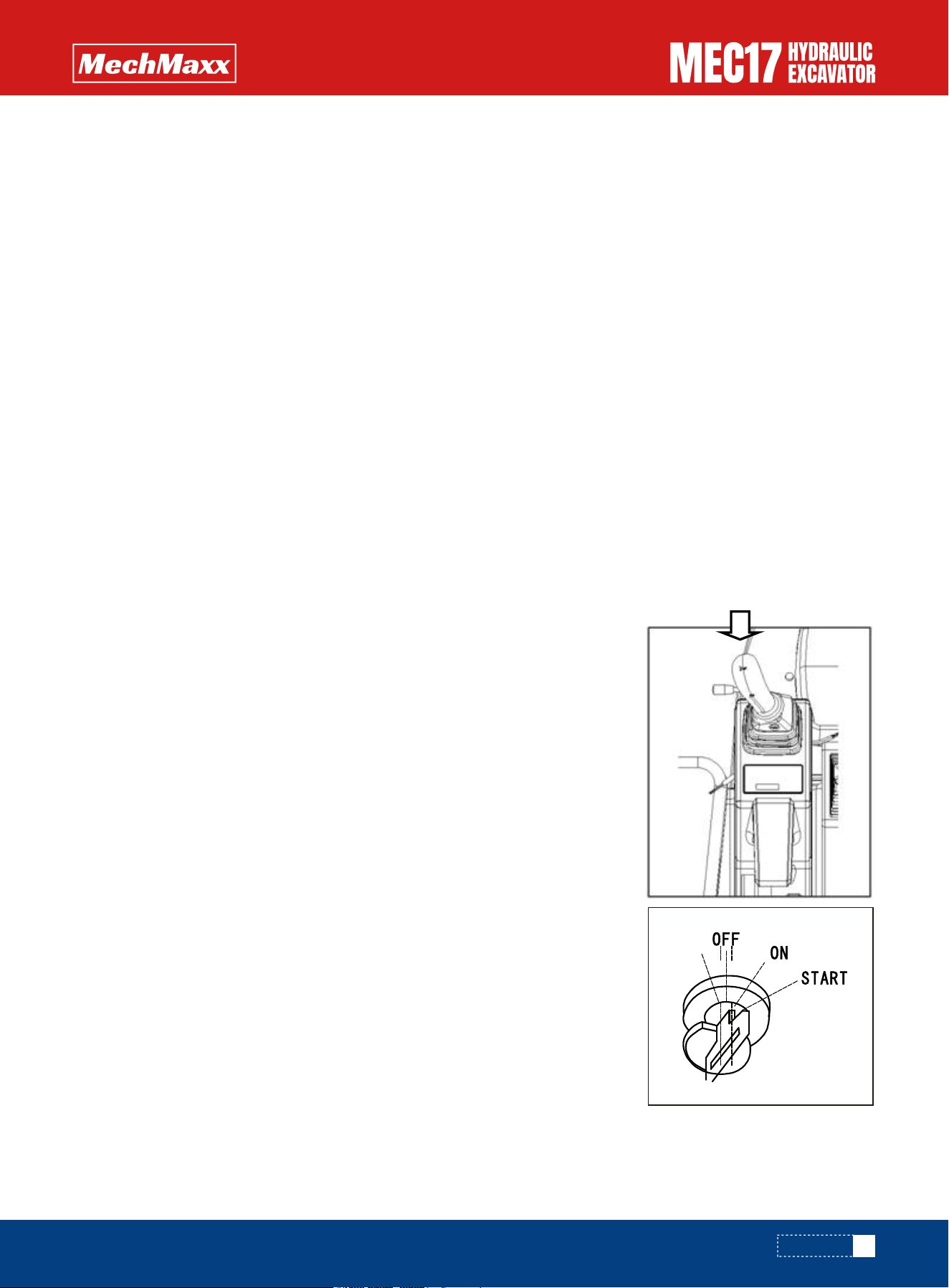
14.Electric lock
15.Seat
16.Seat belt
Before reading this chapter, please read and understand the security component.
WARNING
35
www.mechmaxx.com
OPERATION

Description of Instrument and Control Device
Monitor
Home Screen
The followings are the descriptions of how to operate the devices on the machine. In order to operate the devices correct-
ly and safety, you shall understand the operation method and the meaning of the display.
The main interface displays the working status, alarm signals, operation tips, etc. The display interface is a black back-
groud with different icons, and when special function alarm occurs, the icon will be highlighted.
Please strictly follow the above mentioned requirement to ensure the normally operation of the machine.
When the instrument is powered on, it will show the following logo for 3 seconds, then enter into the user log-in interface
or main interface:
Monitor Specification
Power On:
1.Voltage: 24V DC ( 6~30V DC)
2.Operating Temperature: -30~+75℃ (-22~167℉)
3.Storage Temperature: -40~+85℃ (-40~332.6℉)
4.RH Humidity: 30%~90%
5.Atmospheric Pressure: 86~106 kpa
6.Protection level: IP65
36
www.mechmaxx.com
OPERATION

User Log in Interface:
Main Interface:
When the identity authentication is enabled, the instrument will automatically enter the user login interface(as shown in
the figure below) for identity authentication. This function can be turned on or off in ‘Main Menu-Operator Settings- Identi-
ty Authentication’. The login password can be modified in ‘Main Menu- Operator Settings- Password Modification(default
login password is 0000).
System Voltage:
Indicates the current system voltage value, range from 6~30V.
Beijing Time:
Indicates the current date and Beijing time.
Pilot Switch Indication:
Indicates the pilot switch status.
Water Temperature Pointer Dial:
Indicates the current engine water temperature. When the temperature is higher
than the alarm point, the icon on the main interface is always on, and the text will prompt ‘The cooling water is too
high, please check!’ with buzzer sounds.
Warm Up Indication:
Indicates the current preheating status.
Oil Level Pointer Dial:
When the fuel level value is lower than the alarm point and lasts for 20 seconds, the iconon the
main interface will be always on, and text prompts ‘The fuel level is low, please check’ with the buzzer sounds.
Engine Speed:
Indicates the current engine speed, range from 0~3000rpm.
Tex Alarm:
When the text alarm occurs, the specific text alarms will be displayed in this area, and if there are multiple
text alarms, each text alarm will be displayed in turn.
Working Hour Meter:
Indicates the current working hour. When the engine speed is ≥650rpm or the charging signal
line AMP34-21 is suspended or connected to a high level, the hour meter starts timing.
Menu Button:
Pressure this button to enter the main menu interface.
37
www.mechmaxx.com
System Voltage
Beijing Time
Pilot Switch Indication
Water Temperature
Warm Up Indication
Oil Level Pointer
Engine Speed
Tex Alarm
Working Hour
Menu Button
Air Filter Alarm
High/Low Speed
Charging Indication
Boom Light Button
Oil Pressure
Mute Button
OPERATION
Main Interface Main Menu
Operating Parameters
Machine Information
Instrument Information
Identity Authentication
Password Modification
Preheating Function
Preheating Time
Clock Setting
Language Setting
Brightness Setting
Key Sound Setting
Alarm Parameter Setting
Machine Information Setting
Set Hour Meter Manually
Factory Initialization (Not Currently Open to User)
Recover Default Parameter(Password:8888)
Machine Information
Operator Setting
(Password:8888)
Preheating Setting
User Setting
System Setting
(Password:8888)
Instrument Setting
(Password:1234)
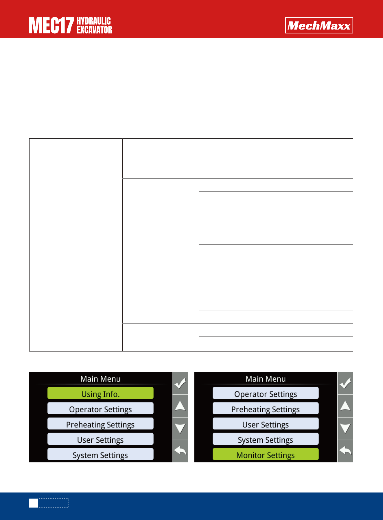
Menu Interface:
Main Menu Renderings:
Air Filter Alarm Indication:
Reserved function to indicate when air filter is blocked.
High/Low Speed Button:
Press this button to switch between ‘High Speed Mode’ and ‘Low Speed Mode’.
Charging Indication:
Indicates the current engine charging status.
Boom Light Button:
Press this button to turn on or turn off the boom light.
Oil Pressure Indication:
Indicates the current oil pressure.
Mute Button:
When there is a buzzer, you can use this button to mute the sound. When the buzzer is in the mute
status, you can cancel the mute by pressing this button.
38
www.mechmaxx.com
OPERATION

Running Parameters: Display the parameters or status of current system, viewing by pressing the button.
Machine Information: Indicates the machine serial number and the service number.
Monitor Information: Indicates Monitor diagram number, Monitor serial number and the software version.
39
www.mechmaxx.com
OPERATION
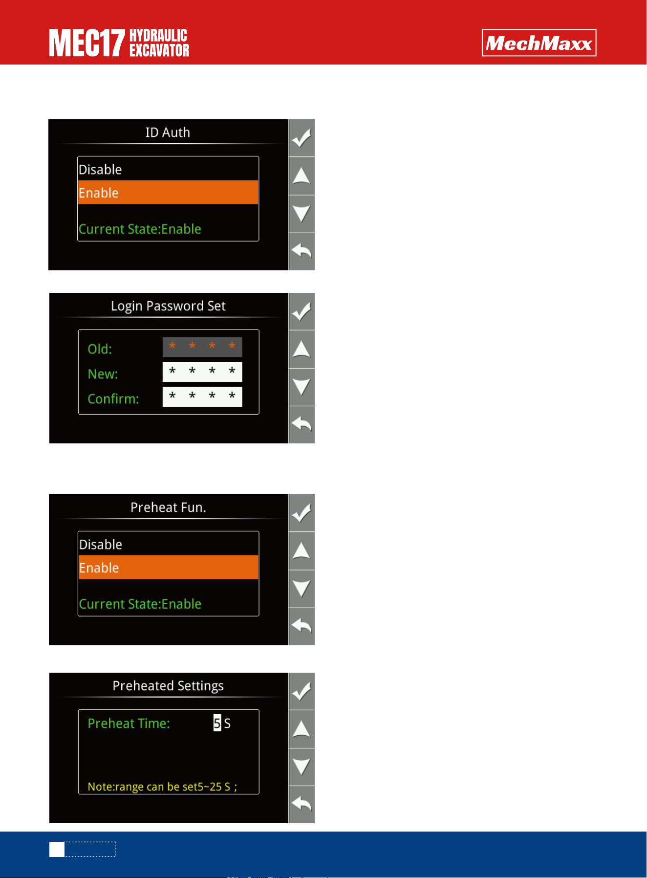
Identity Authentication: You can set the authentication function on or off. When the function is enabled, it will enter the
user login interface every time when the power is on. When the function is off.
Login Password Set: Modify the user login password.( The default login password is 0000).
Preheat Function: You can set the preheat function to be on or off. When the preheat function is on, and the engine
temperature is less than or equal to 40°C, the monitor will automatically preheat once when the power is on. When the
preheat function is off, the automatic preheating will not be performed.
Preheat Time: You can sent the automatically preheat time.
40
www.mechmaxx.com
OPERATION

Adjust Clock: You can set the current date and the time.
41
www.mechmaxx.com
Brightness Setting: You can set the brightness of the screen.
Key Sound Setting: You can set the key sound, the factory default is Enable.
Alarm Date Setting: You can set the low oil level alarm point and the high water temperature alarm point. The factory
default low oil level point is 10% and the high water temperature alarm point is 102℃.
OPERATION
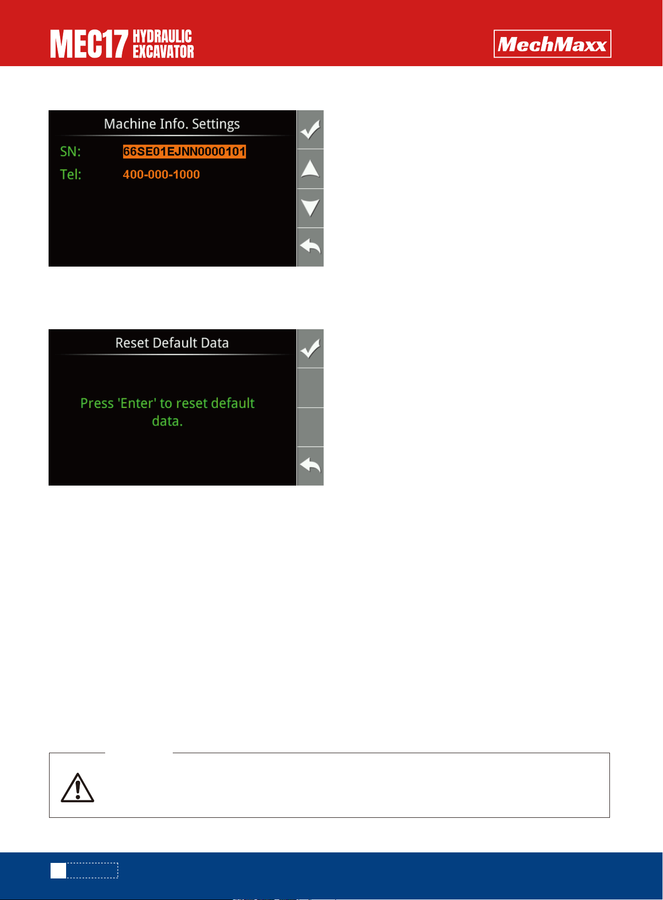
Machine Information Setting: You can set the serial number and service phone number
Factory Initialization: Not open to the user.
Reset Default Data: After performing ‘Reset Default Data’. the low oil level alarm point will be restored to 10%, and the
high water temperature alarm point will be restored to 102℃, and the user login password will be restored to 0000.ser.
While displaying the working status, the monitor can also monitior the working satus of the engine’s lubrication system,
cooling system, intake system, and engine system.
1.High coolant temperature alarm: Indicates that coolant temper ature is higher than the set value. In the event of a
coolant temperature alarm, check in time whether the cooling system is short of coolant and whether there is cool ant
leakage, check whether the actual temperature of the water the coolant temperature sensor circuit is short.
2.Low oil pressure alarm: mainly from the following three aspects of troubleshooting
•Is the engine oil filter dirty?
•Is the engine oil pump working properly?
•Is there a lack of engine oil?
3.High hydraulic oil pressure alarm (only for models equipped with hydraulic oil pressure sensor): The pressure of the main
pump of the hydraulic system is higher than the set pressure, and it is mainly checked from the following aspects:
•Check whether the main relief valve on the main valve is normal;
•Otherwise, please contact your nearest dealer for assistance.
Alarm Fault Handling and Troubleshooting
As soon as this alarm signal is displayed, it should be stopped immediately for inspection, other-
wise the system will qutomatically reduce the engine speed to idle after the set time and record the
failure time.
WARNING
42
www.mechmaxx.com
OPERATION
Low coolant level alarm: indicates that the liquid level of coolant in the cooling system is lower that the safe value, and
should be checked at this time:
•Is the coolant in the auxiliary water tank below low?
•Whether the radiator is short of coolant, and whether there is a leakage in the radiator and the seals of each pipe.
Low fuel level alarm: indicates that the actual oil storage in the mailbox, at this time, check the fuel level in the fuel tank
and fill up the fuel in time.
Air filter blockage alarm: indicates that the main filter element of the air filter is dirty, and the filter element of the air
filter should be cleaned or replaced at this time.
Abnormal battery voltage: Low battery voltage: indicates that the battery voltage is below the set lower limit. At this
point, try starting the engine once and determine the fault based on the actual situation:
•If the battery can start normally and the alarm disappears after ten minutes of machine operation, it belongs to a slight
power loss and can be charged for a long time to solve the problem.
•If it can start normally and still alarm after ten minutes of machine operation, it is necessary to check whether the
generator and charging circuit are normal and whether the battery is damaged.
•If the battery cannot start normally, it is considered to be severely depleted or damaged, and the battery should be
repaired or replaced.
Battery voltage too high: indicates that the battery voltage is higher than the upper limit of the set value. At this time,
the actual voltage of the battery should be measured (the working voltage should be 9V-16V when the engine is running
normally). If the measured voltage is greater than 16V, the generator is faulty and should be repaired or replaced.
Other Control Devices
Speaker switch
When press the button on the top of the left control level, the speaker will sound.
Speaker function-check
1. Turn the key switch to the ON position.
2. Confirm that the speaker will sound when the speaker button on the right handle
is pressed. If the speaker does not work, please contact mechmaxx dealer for repair.
Start switch
The switch is used to start or shut down the engine.
•OFF position
The key can be inserted or removed. All switches of the electrical system are closed
and the engine is stopped.
•ON position
Current flows in the charging and lamp circuits. When the engine is running, keep the
starter key in the ON position.
•START position
This is the engine start position. When starting the engine, keep the key in this
position. After the engine starts, release the key immediately and it will automati-
cally return to the ON position.
•HEAT (preheat) position
When starting the engine in winter, you must first turn the key to this position. The
preheating time does not exceed 15s, and the preheating will be automatically
disconnected if it exceeds 15s. After preheating, release the key immediately and it
will automatically return to the OFF position.
43
www.mechmaxx.com
HEAT
OPERATION
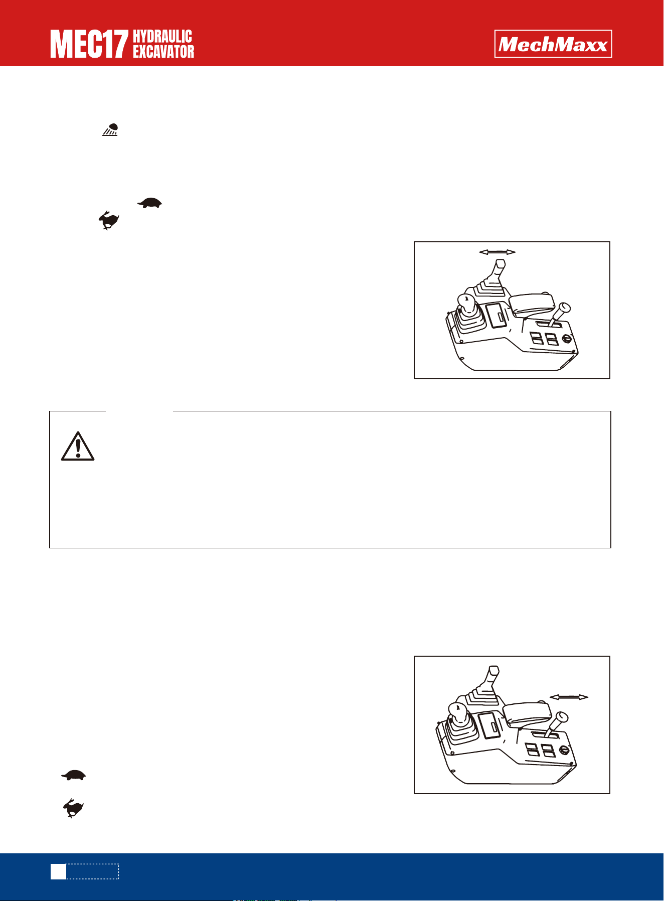
Work light switch
Control the switch of the boom work light
•Press ON position: The light is ON.
•Press blank position: The light is OFF.
Two-speed switch
This switch is used to select low or high speed.
•Press to blank or position: walking at low speed.
•Press to position: walking at high speed.
•When using a bulldozer to excavate continuously for more than 1 hour, pay
attention to the rise in water temperature during this period. Used to
control the lifting and falling of the bulldozer.
•Rear: The bulldozer is lifted, (after the function handle is switched) the
chassis is retracted.
•Front: The bulldozer drops, (after the function handle is switched) the
chassis extends.
•LOCK position: The engine can be safely started or the operation can be stopped.
•FREE position: The excavator is allowed to operate normally.
This knob is used to control engine speed and output power.
• For the low speed position: push forward to reduce engine speed
and power.
• For the high speed position: Pull back to increase engine speed and
power.
•When the lock lever is at the LOCK position, allow to start the engine only,
otherwise it can not work.
•The lock lever is at the FREE position, if the engine stops, set the lock
lever to the LOCK position, then start the engine again.
Notice:
This lock lever is of hydraulic lock type. Accordingly, when it is in the lock position, the control levers or control
pedals move but the machine does not move.
Notice
This lever is a device to lock the work equipment, swing, travel, and attachment (if equipped) control levers.
Bulldoze (chassis telescopic) joystick
Lock lever
Throttle knob
Notice
• When leaving the operator's seat, set the lock lever securely to the LOCK position. If the lock lever
is not at the lock position, and the control levers are touched by mistake, it may lead to serious
personal injury.
• If the lock lever is not securely at the LOCK position, the lock lever may be moved, it may lead to
serious accident or injury.
• When pulling the lock lever up, be careful not to touch the work equipment control lever.
• When pushing the lock lever down, be careful not to touch the work equipment control lever.
WARNING
44
www.mechmaxx.com
OPERATION
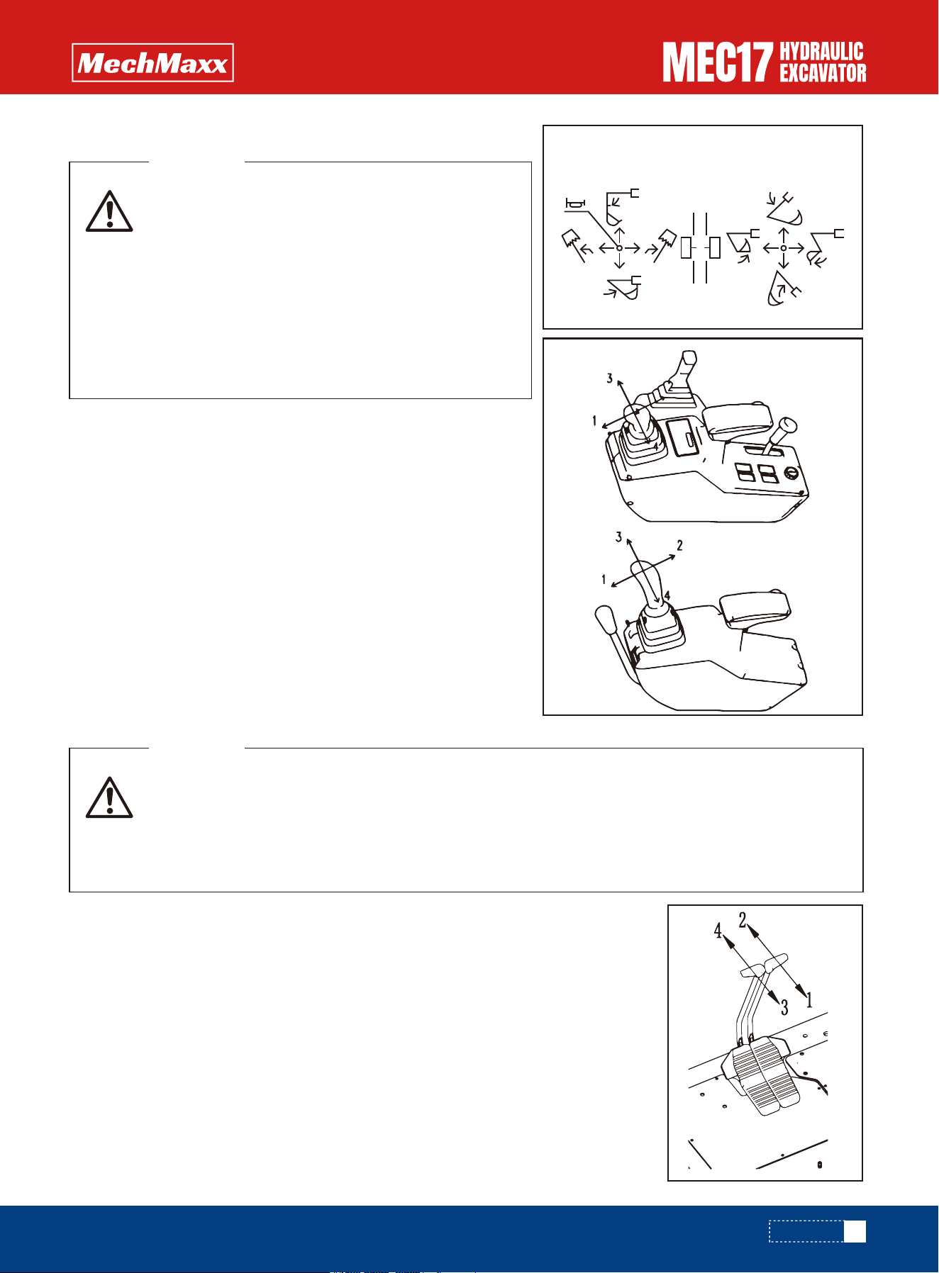
Working device control handle
Travel levers
Left work equipment control lever is used to turn and operate the arm.
•1 Arm OUT
•2 Arm IN
•3 Swing to LEFT
•4 Swing to RIGHT
Right work equipment control lever is used to operate the boom and
bucket.
•1 Boom LOWER
•2 Boom RAISE
•3 Bucket DUMP
•4 Bucket CURL
Middle: The upper body and stick, boom and bucket remain in place.
This lever is used to change the direction of travel between forward and reverse.
•Operating 1,3 simultaneously: retrogression.
•Operating 2,4 simultaneously: forward.
•Separate operation 4 or1: turn right
•Separate operation 2or3: turn left
•Operating1 or 4 simultaneously: turn right around
•Operating2 or 3 simultaneously: turn left around
When the lever return to the middle position, the machine stops.
• Operation mode is set to standard mode(ISO
mode)
• When you need to change the mode of operation,
please contact the dealer.
• When changing the mode of operation, please
replace operation signs to ensure consistent with
the operation of the machine.
• The sticking position is locked on the right side of
the seat.
WARNING
• Do not rest your foot on the pedal during operations.
• When operating the walking handle/pedal (Optional), determine the walking direction of the crawl-
er.
• The following description is for when the driving wheel is at the rear and the driving wheel is at the
front, the walking operation sequence is reversed.
WARNING
45
www.mechmaxx.com
ISO MODEL
OPERATION
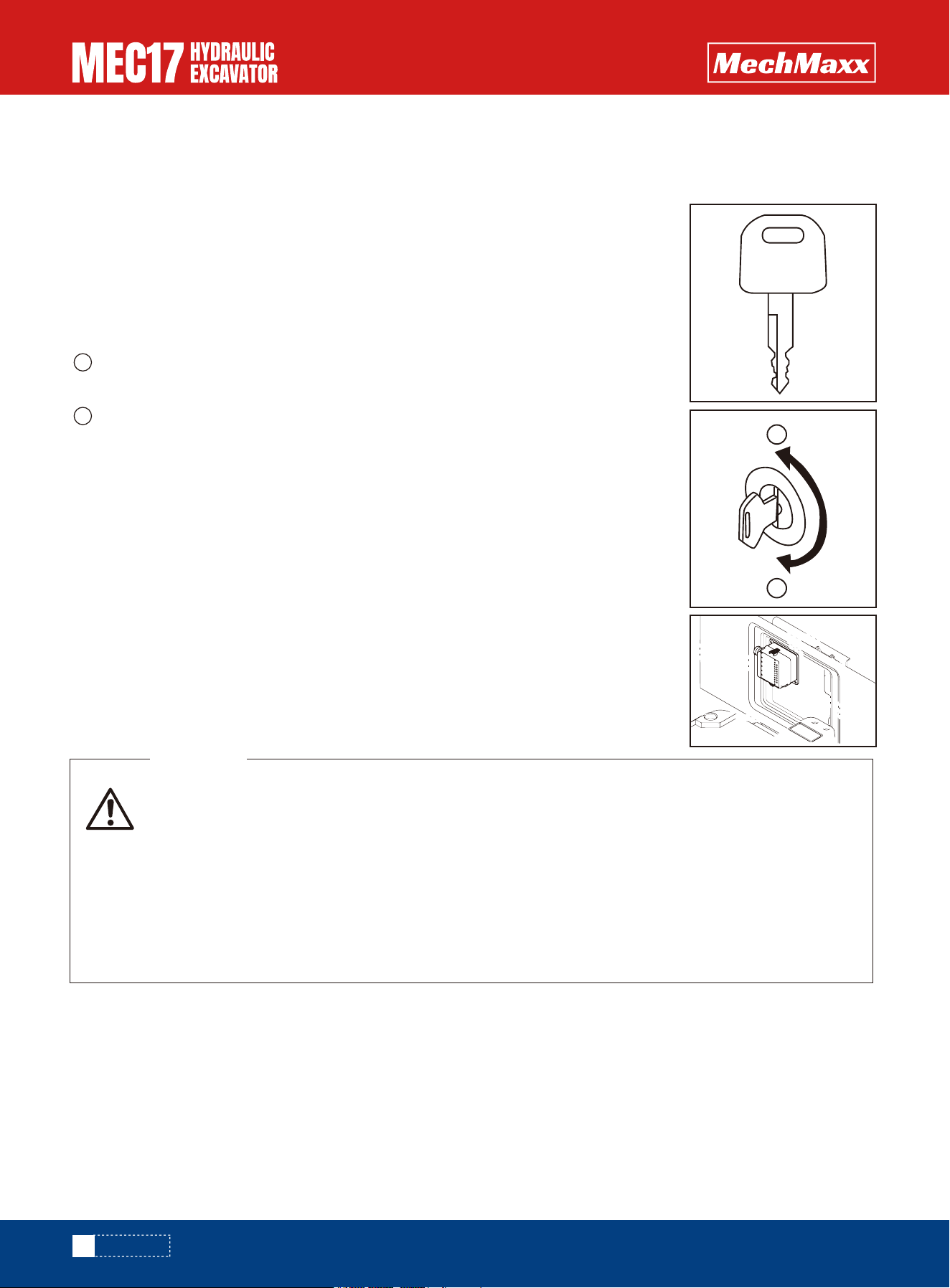
Equipment Lock
Both the fuel tank filler opening and the engine cover are equipped with locks. A key is required to open and lock these
locks.For the location of the device lock, see the item "Locked".
There are three positions of the lock here. When the key is turned or released later, the key
will automatically spring back to the middle position following the lock cylinder.
B Opening the Lock
Insert the key into the key slot. Turn the key clockwise, then open the lock.
A Locking the Lock
Insert the key into the key slot. Turn the key anticlockwise, then lock it.
Insert the key the end, then turn the key clockwise. If the key is turned before it is inserted
all the way, it may break.
Notice
The machine is equipped with a central controller, which is installed under the
seat. The internal fuse can prevent electrical equipment and wires from burning
out. If the fuse box fuse is corroded or white powder can be seen, or the fuse is
loose in the fuse holder, replace the fuse.
Fuse
Fuel tank filling port and engine hood lock
• Before replacing a fuse, be sure to turn off the starting switch.
• Do not install the fuse that is specified on the label, otherwise there is a risk of damage to the
circuit board or fire.
• Fuse burn off, must identify the cause of the fault, the party can be replaced.
• After the fuse is blown out, the fuse must be replaced with the same standard.
• When the fuse is corroded, the surface appears white powder or fuse is loose, should check and
timely.
• The fused fuse can not be repaired, and should be replaced in a timely manner.
WARNING
46
www.mechmaxx.com
A
B
OPERATION
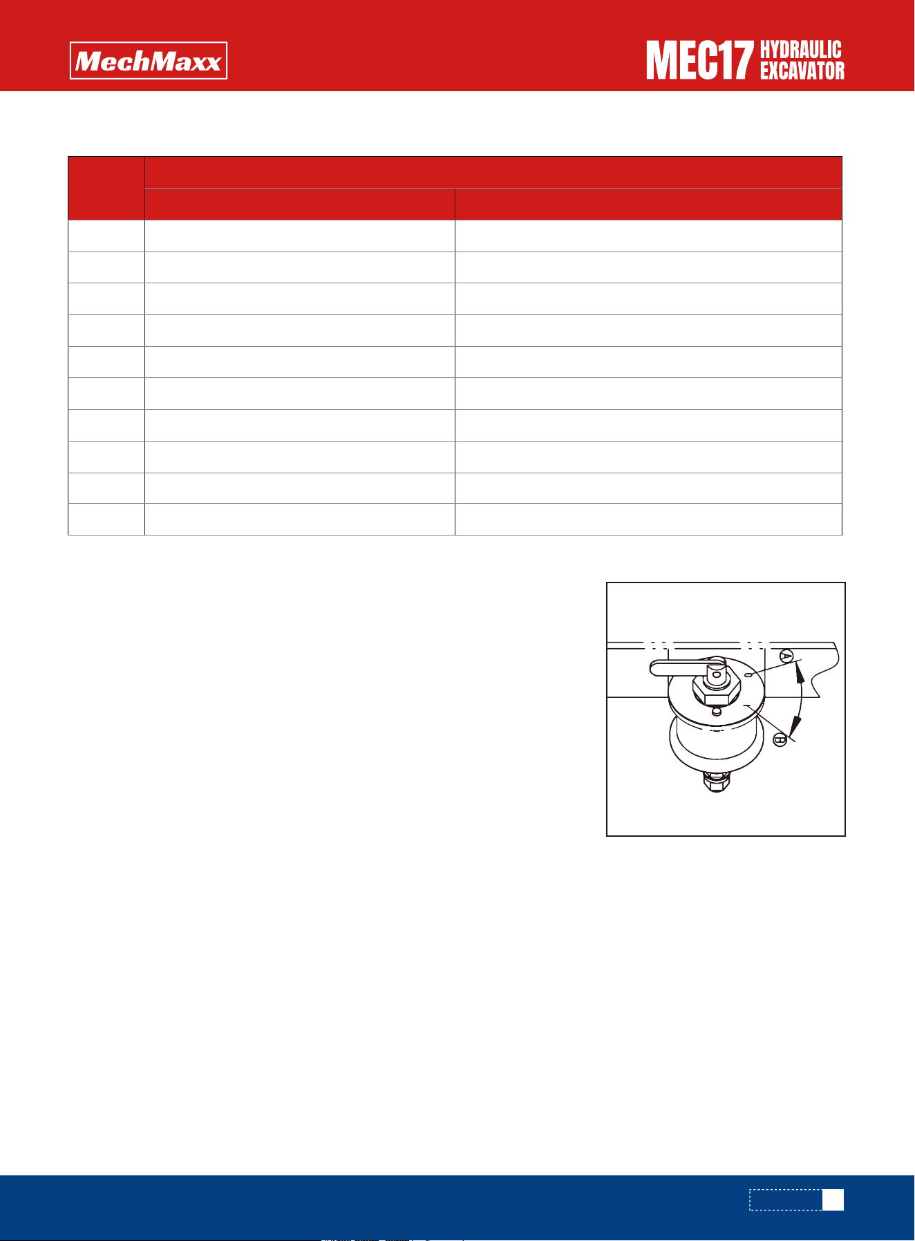
1
2
3
4
5
6
7
8
9
10
20A
20A
15A
15A
5A
10A
5A
10A
20A
20A
Start loop
Charging loop
Fuel pump
Instrument
Pilot circuit
working lamp
High and low speed
trumpet
spare
spare
fuse capacity electrical name
Number
MEC17
Battery Disconnect Switch
Fuse capacity and electrical name (from left to right, from top to bottom)
In addition to the following cases, this switch should be in the I (electrify)
position,.
•Long term storage machine (more than one month)
•When repairing the electrical system
•When welding
•When handling the battery
•When replacing fuses and other parts
If you switch to the O (OFF) position, all electrical systems are switched off. This
switch is used to cut off the current from the battery. Located in the machine right
cover, you can see it when open the foot pad.
A: O, (Off) position
B: I, (Electrify) position
Before operating the machine, always place the switch in position I.
IMPORTANT
47
www.mechmaxx.com
OPERATION
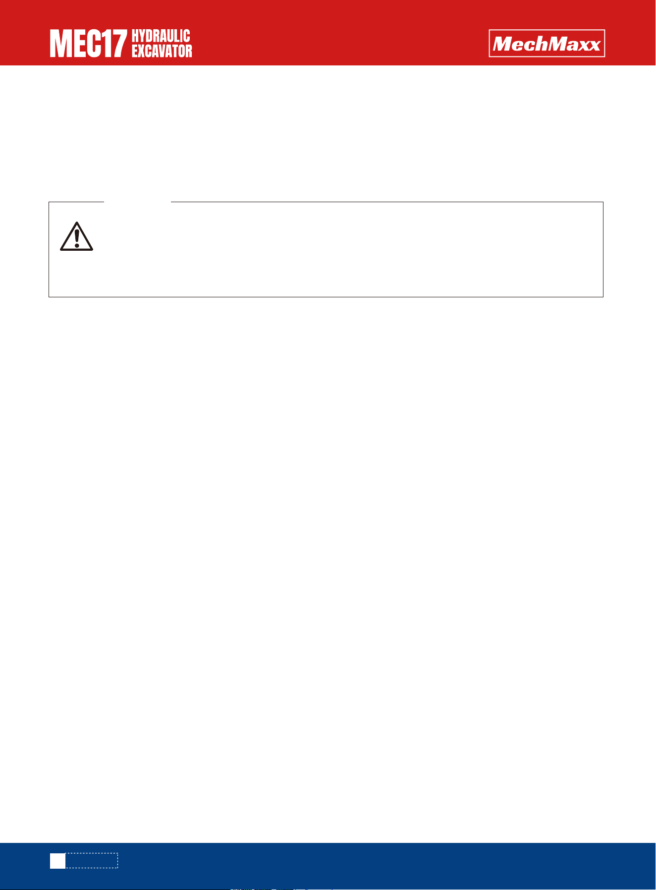
Machine Operations and Controls
Checks before Starting
Before Starting Engine
Walk-around checks
Before starting the engine, look around the machine and under the machine to check for loose nuts or bolts, or leakage of
oil, fuel, or coolant, and check the condition of the work equipment and hydraulic system.
Check also for loose wiring, play, and accumulation of dust at places, which reach high temperatures.
During the inspection, if the machine is tilted, make it level before proceeding with the inspection. Before starting the
engine every day, check the following items in this section.
1.Check whether the working device, cylinder, connecting rod, hose are damaged, worn or have gaps
Check the working device, cylinder, connecting rod or hose for cracks, excessive wear or gaps. If any problem is found,
repair it.
2.Remove dirt and debris from around the engine, battery, and radiator.
Check for dirt accumulated around the engine and radiator. Also check for flammable material (dry leaves, twigs, etc.)
around the battery, engine muffler, turbocharger, or other high temperature engine parts. If any dirt or flammable materials
are found, remove them.
3.Check for coolant and oil leakage around the engine.
Check for oil leakage from the engine and coolant leaks from the cooling system. If any problem is found, repair it.
4.Check for oil leakage from hydraulic equipment, hydraulic tank, hoses, and joints
Check for oil leakage.
If any problem is found, repair the area where oil is leaking.
5.Check whether the grease pipeline leaks grease.
If any problem is found, repair it.
6.Check whether the monitor is damaged and whether the bolts are loose.
The monitor should be undamaged. If an abnormality is found, replace the parts. Remove foreign objects on the surface.
7.Seat belt and mounting clamps
Check for damage or wear to the seat belt and mounting clamps. If there is any damage, replace with new parts.
8.Check bucket with hook (if equipped) for damage.
Check for damage to the hook, guide, and hook mount. If any problem is found, contact your mechmaxx distributor for
repairs.
Always check the items in this section before starting the engine each day.
• Before inspection and maintenance, the rear engine cover, side door and right front cover must be
opened and fixed.
• Clean the flammable materials around the battery, engine muffler or other high-temperature
engine parts. Fuel or oil leakage can cause the machine to catch fire. Check carefully and repair
any abnormalities or contact the dealer.
WARNING
48
www.mechmaxx.com
OPERATION
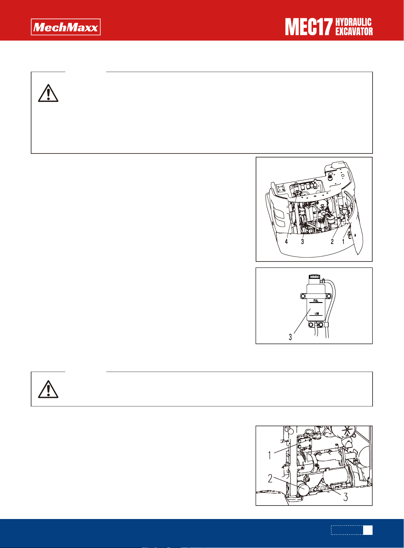
Check and add the machine at the level of the place.
Check the coolant level before starting every day.
1.Open the rear hood (1), and ensure that the support rod (2) falls into the
slot to lock, so as to avoid the side door collision.
2.Check the coolant level of sub-tank (3).
•If the coolant level is between the FULL and LOW marks means normal.
•If the coolant level is low, add coolant to the FULL level through the filler
port of sub-tank (3).
•If the sub-tank (3) is empty, there is probably leakage of coolant. After
inspecting, repair any problem immediately.
3.At the same time of press the radiator cap (4), unscrew the cove until it
comes into contact with the brake and remove the cover. Check the coolant
level of the radiator, if lacking of coolant, then add coolant and check wheth-
er there is any leakage on line.
4.Check the rubber hoses and pipe clamps for damage, cracks and loose-
ness, and tighten them immediately if they are loose. If damaged, the hose or
pipe clamp must be replaced immediately, otherwise the engine is not
allowed to start.
Pipe clamp tightening torque of 5.9±0.49N·m(60±5kg·cm)
When performing inspection and maintenance inside the hood, the hood must be fully opened and locked with struts.
1. Open the hood and lock it with a strut.
2. Remove dipstick (3), and wipe the oil off with a clean cloth.
3. Fully insert dipstick (3) into filler pipe, then remove it.
• Do not open the radiator cap unless necessary. Wait for the engine to cool down before checking
the coolant in the sub-tank.
• Immediately after the engine is stopped, the coolant is at a high temperature and the radiator is
under high internal pressure.
• If the cap is removed to check the coolant level in this condition, there is a hazard of burns. Wait
for the temperature to go down, then turn the cap slowly to release the pressure before removing
it.
WARNING
Parts and oil are at high temperature immediately after the engine is stopped and may cause
serious burns. Wait for the oil temperature to go down before performing this operation.
WARNING
49
www.mechmaxx.com
Coolant Level: Check or Add
Oil Level in Engine: Check or Add
OPERATION
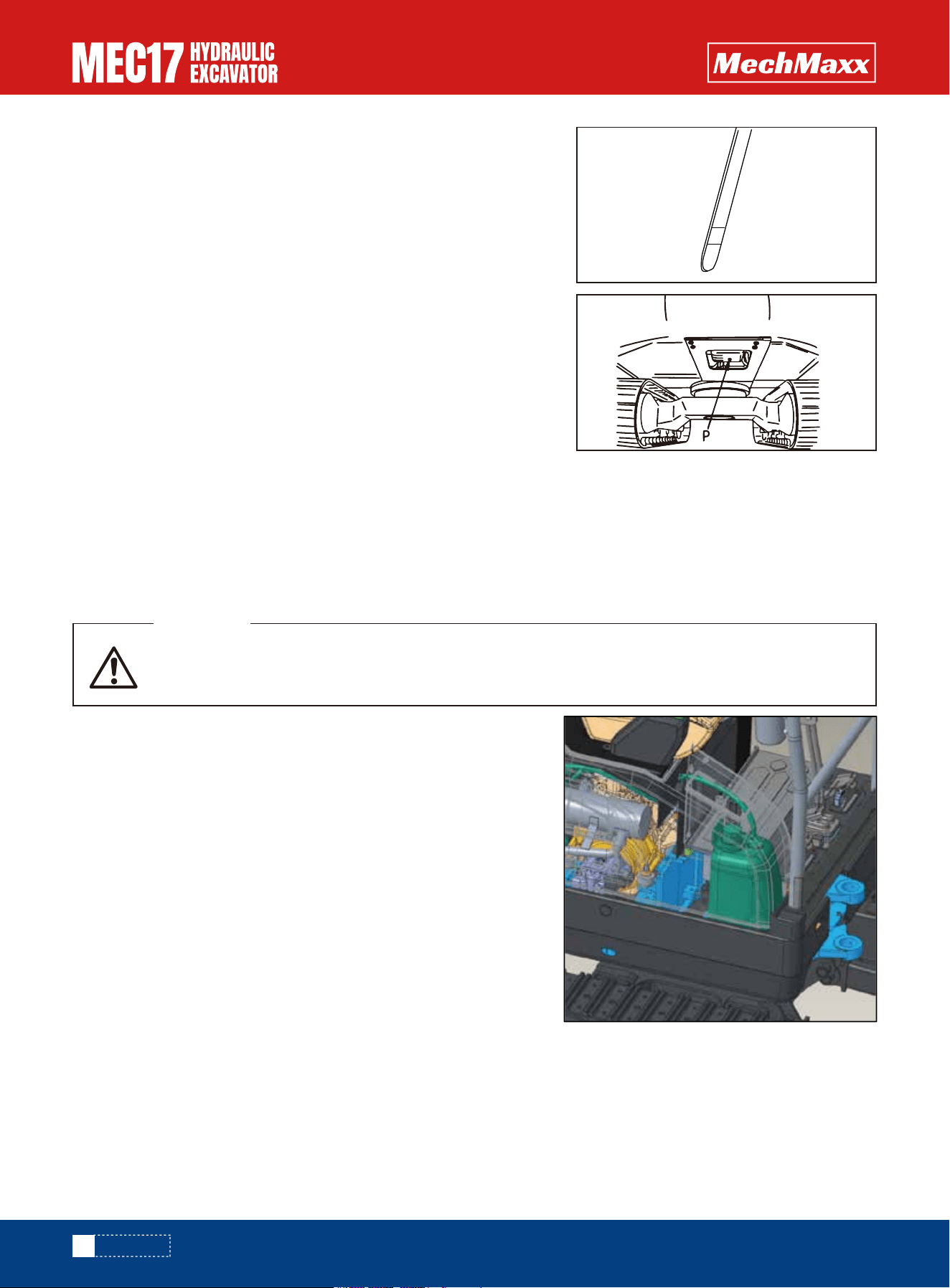
4. The oil level should be between the H and L marks on dipstick (3).If
the oil level is below the L mark, add engine oil through oil filler (1).
5. If the oil is above the H line, open drain valve (P) at the bottom of the
engine oil pan, drain the excess engine oil, then check the oil level
again.
6. If oil level is correct, securely tighten the oil filler cap and close the
engine hood.
NOTICE
•When checking the oil level after the engine has been operated, wait for at least 15 minutes after stopping the engine
before checking.
•If the machine is Inclined, make it to a horizontal position before checking.
•The position of dipstick and discharge plug may be different for different models.
2.If the fuel level is within the red scale of the oil level, add fuel
through the injection port (F).
Fuel tank capacity: 19 liters
3. Tighten the cover and locked after refueling.
1. According to the fuel oil level on the monitor to check the amount of
oil in tank.
When adding fuel, never let the fuel overflow. This may cause a fire. If any fuel is spilled, wipe it up
completely. Never bring flames near fuel because it is highly flammable and dangerous.
WARNING
50
www.mechmaxx.com
Fuel Level: Check or Add
H
L
OPERATION
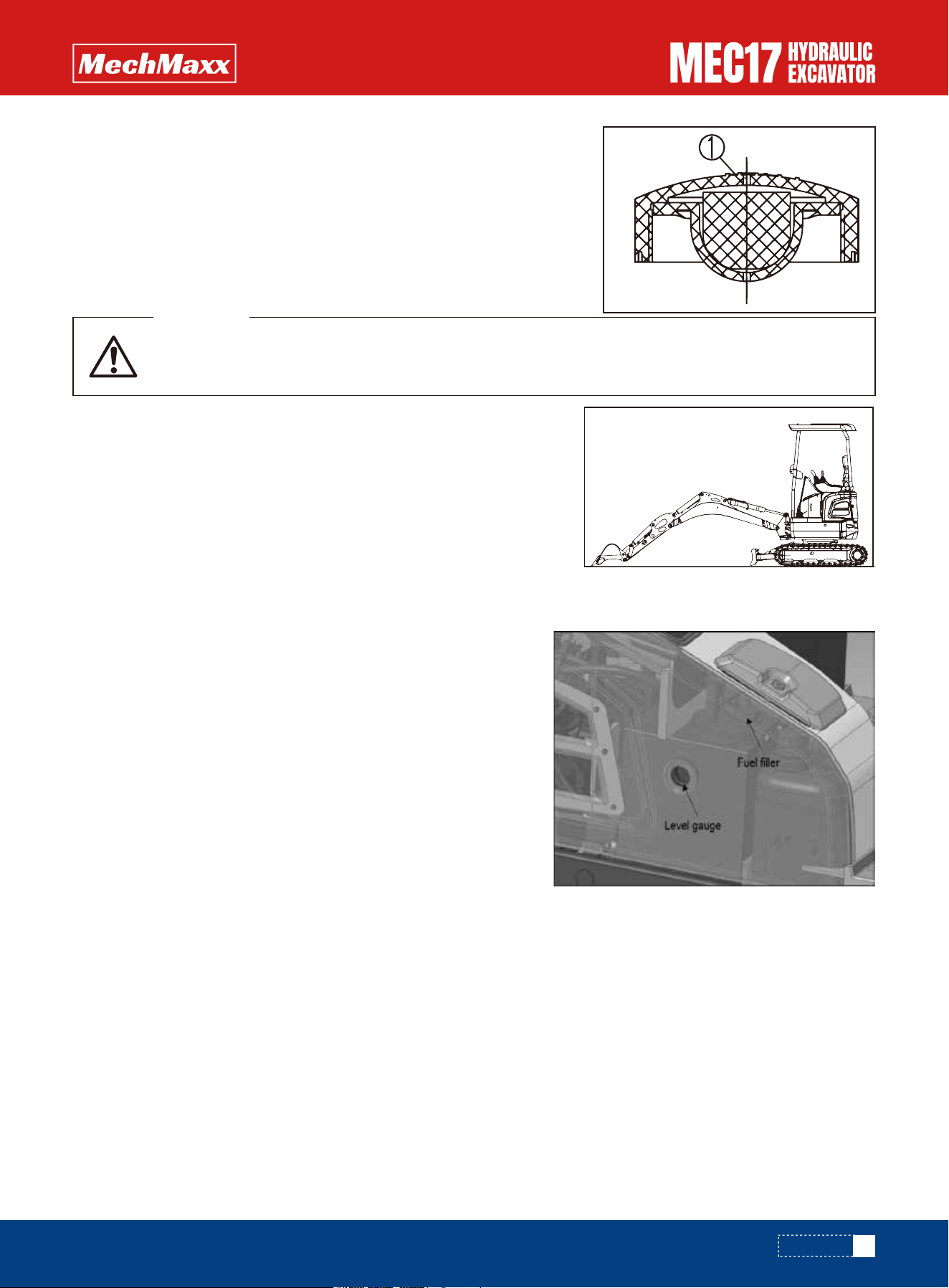
REMARK
•If breather hole ① in the cap is clogged, the pressure in the tank will drop and
fuel will not flow.
•Clean the hole from time to time.
The refueling steps are as follows:
1. Use the key to open the fuel cap lock;
2. Unscrew the fuel filler bolt;
3. Add hydraulic oil and check the level gauge again;
4. Tighten the fuel filler bolt and lock the fuel filler lock.
If the working device is not in the state shown in the figure on the
right, start the engine and run the engine at a low idle speed. Fully
retract the arm and bucket cylinder rod, then lower the boom, adjust
the bucket teeth to the ground contact position, and turn off the
engine.
Check the level gauge on the hydraulic oil tank. The oil level must be
between the marks on the level gauge, otherwise hydraulic oil needs
to be filled.
Within 15 seconds after turning off the engine, turn the safety lock switch to the ON position, and operate the joystick
(working device, walking) in each direction to release the internal pressure.
After stopping the engine, the parts and hydraulic oil are still at high temperature, which may cause
burns. Therefore, wait until the temperature drops before starting work.
WARNING
51
www.mechmaxx.com
Oil Level of Hydraulic :Check or Add
OPERATION
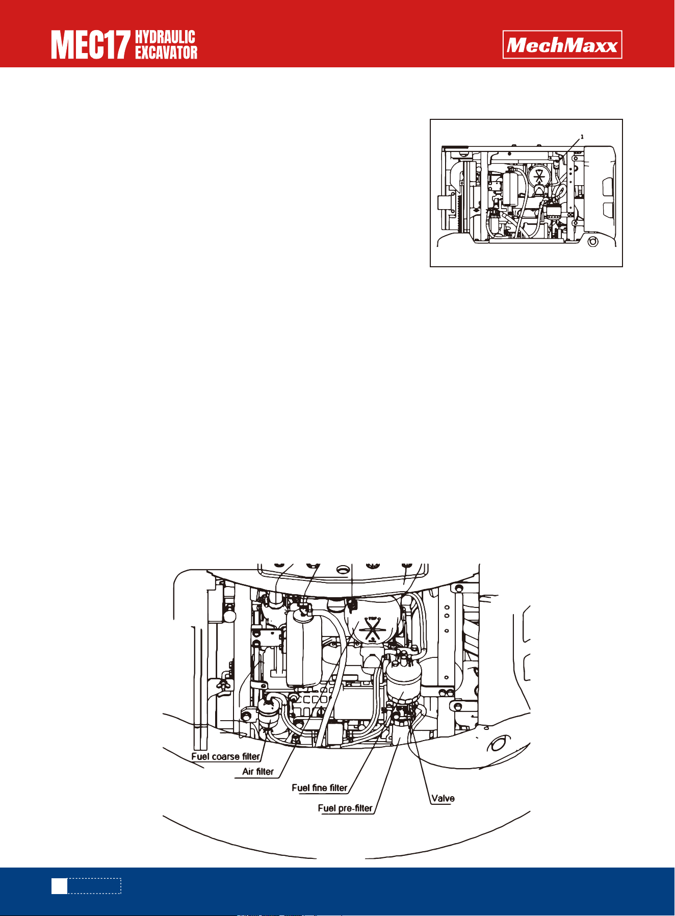
IMPORTANCE
IMPORTANCE
Fuel pre-filter: check or drain or clean
•Only when the pressure difference indicator (1) pops out and the red mark is
visible. The air filter needs to be cleaned, otherwise there is no need to clean
the air filter element.
•If the air filter element is cleaned frequently before the pressure difference
indicator has not warned, The performance of the air filter will not be fully
exerted, and its filtering effect will be deteriorated.
•In addition, the dirt attached to the filter element during cleaning will
frequently fall to the inner filter element side and be sucked into the engine,
causing engine wear.
The fuel pre-filter is inspected and drained, and cleaned if necessary:
1. Open the rear hood of the engine and lock it with a strut.
2. Observe the water cup. If there are impurities inside the water cup, close the valve, place a cloth outside the water
cup, use the filter element wrench to turn left to remove the water cup, and clean the water cup with clean diesel.
3. After the water cup is cleaned, use the filter element wrench to turn clockwise to install the water cup back.
4. Open the valve, loosen the strut, and close the rear hood of the engine.
•The collector cup need to emissions, should not until the pre-filter separator alarm after discharge set the water in the
glass, once the fuel oil mixed with water, will cause harm to the engine.
•When the water cup has impurities, need to clean the collector cup immediately, or else impurities into the engine block,
or engine early wear.
•The location of the fuel prefilter may be different for different models.
When the pressure difference indicator (1) pops up and shows red, clean or replace the filter element immediately.
For details about cleaning the filter element, see "Air Filter-Inspection/Cleaning/Replacement" in Inspection and Mainte-
nance.
52
www.mechmaxx.com
Air Cleaner Dust Indicator (optional): Check
OPERATION
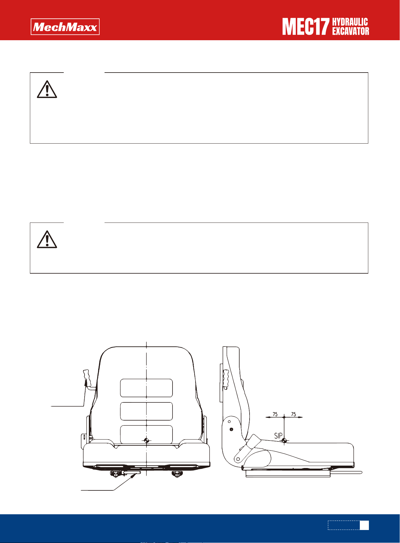
IMPORTANCE
In order to obtain the best possible comfort, it is important to adjust the seat in the correct way.
Statement: Assemble different types of seats and seat adjustment methods are different, please operate according to
the actual situation.
Check whether the fuse is damaged and the capacity of the fuse used is appropriate. Check the circuit for signs of open
circuit or short circuit, and check whether the terminals are loose. Tighten the loose terminal.
Pay particular attention to the electric wiring when checking the battery, engine starting motor and alternator.
Also check that there is no inflammable material accumulated around the engine. If present, remove it as soon as possi-
ble.
For inquiries about the causes and corrective suggestions, please contact your mechmaxx distributors.
• If the fuses frequently blow or if there are traces of short circuits in the electrical wiring, locate the
cause and immediately perform repairs, or contact your mechmaxx distributor for repairs.
• Be sure to check that there is no inflammable material accumulated around the battery. If present,
remove it as soon as possible.
• Keep the top surface of the battery clean and check the breather hole in the battery cap. If it is
clogged with dirt or dust, wash the battery cap to clean the breather hole.
WARNING
• Adjust the operator's seat, control box and rear view mirror before starting each operation or when
the operators change shift.
• Adjust the operator's seat so control levers and switches can be operated freely and easily with the
operator's back against the backrest.
WARNING
53
www.mechmaxx.com
Electric Wiring: Check
Adjustment
Seat Adjustment
Weight
adjustment handle
Fre-and-aft
adjustment handle
OPERATION
If the seat belt is worn or damaged or accidentally deformed, replace the seat belt.
If the seat belt needs cleaning, it must be:
Fasten and unfasten the seat belt
1.Sitting in a seat on the seat, allow the operator back against the seat back of a chair, in order to work.
2.Hold grip and pull the belt out from wind-in device, check that the belt is not twisted, then insert tongue into buckle
securely.
3.Remove the seat belt, should carry handle with front end, to remove your seat belt.
•Use neutral soap liquid.
•Before the belt is rolled up, allow it to dry in the sufficiently stretched condition.
REMARK
Adjust the fixed card buckle the length of the side, make against the body and avoid kink belt.
Weight adjustment
According to the operator's own weight, rotate the weight adjustment handle, adjust to the appropriate position. There
are three levels of adjustment gears.
Fore-and-aft adjustment
Lift up the seat lever to adjust the entire seat forward or backward. The maximum seat adjustment is 75mm. (This adjust-
ment is the adjustment of the seat rod itself, does not include the adjustment of the slide plate)
Backrest angle adjustment
The seat back can be adjusted forward or backward by a total of 15°.
Seat belt
• Before fitting the seat belt, check that there is no problem in the belt mount bracket or mounting
belt. If it is worn or damaged, replace the seat belt.
• Even if no problem can be seen in the belt, replace the seat belt every 2 years.
• To adjust seat before operation.
• Always wear the seat belt during operations.
• Fit the seat belt so that it is not twisted.
WARNING
• When starting the engine, check that the lock lever is securely at the LOCK position.
• If the lock lever is not locked securely and the control levers or control pedal are touched when the
engine is started, the machine may move unexpectedly, and this may lead to serious personal
injury.
• When standing up from the seat, be sure to set the lock lever at the LOCK position, regardless of
whether the engine is running.
WARNING
54
www.mechmaxx.com
Operations before Starting Engine
OPERATION
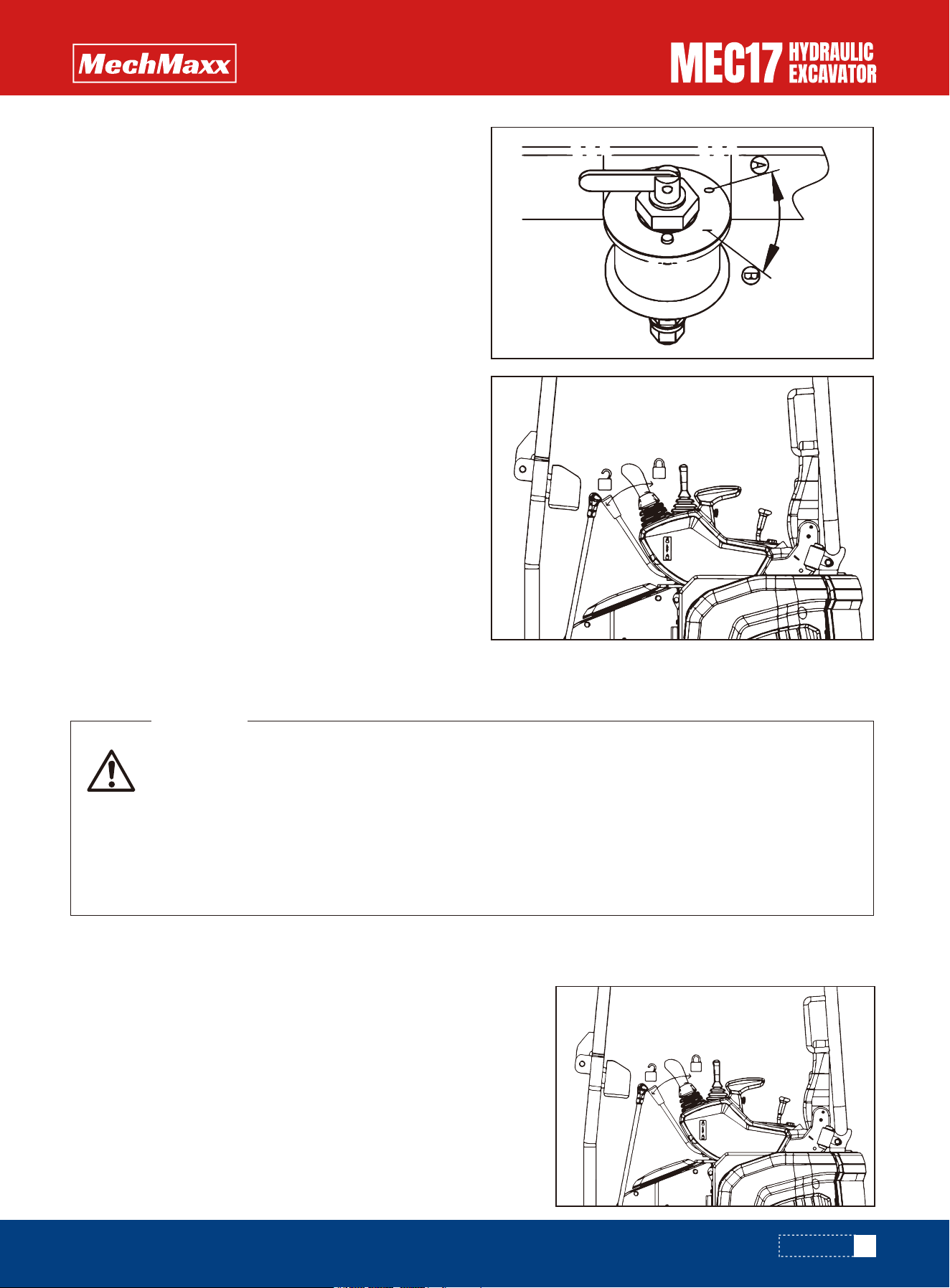
1. Confirm the battery cut-off switch in position I (electrify).
2.Check if the lock lever is at the LOCK position.
If lock lever is not at the LOCK position, do not starting
engine..
Do not crank the starting motor continuously for more than 20 seconds. If the engine does not start, wait for at least 2
minutes be fore trying again.
1.To ensure the safety lock handle in the locked position, if the safety
lock lever is not in the locked position, don't start the engine.
3.Check the position of each lever.
Normal Starting
IMPORTANCE
• Start the engine only after sitting down in the operator's seat.
• Do not attempt to start the engine by short-circuiting the engine starting circuit. Such an act may
cause a serious bodily injury or fire.
• Check that there are no persons or obstacles in the surrounding area, then sound the speaker and
start the engine.
• Exhaust gas is toxic. When starting the engine in confined spaces, be particularly careful to ensure
good ventilation.
WARNING
55
www.mechmaxx.com
Starting Engine
OPERATION
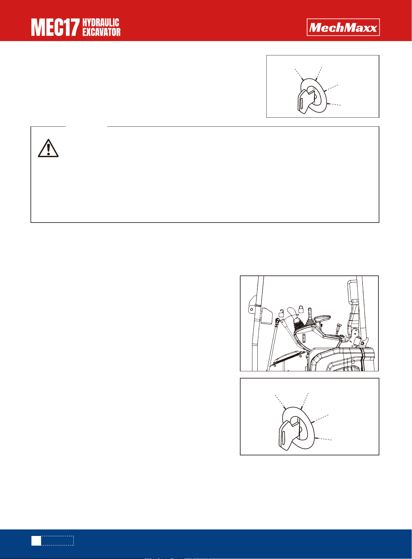
1.To ensure the safety lock handle in the locked position if the safety
lock lever is not in the locked position, don't start the engine.
2.Keep the start switch key at the HEAT (preheat) position, the
preheating time does not exceed 15s, and it will automatically cut off
preheating if it exceeds 15s. After preheating, release the key immedi-
ately and it will automatically return to the OFF position.
3.Turn the key in starting switch to the START position to start the engine.
4.After the engine starts, release the key in starting switch. The key will automatically return to the ON position.
2.Turn the key in starting switch to the START position. The engine will start.
3.After the engine starts, release the key in starting switch. The key will
automatically return to the ON position .
Do not crank the starting motor continuously for more than 20 seconds. If the engine does not start, wait for at least 2
minutes before trying again.
When starting in low temperatures, do as follows (Machine with warm-up function performs this operation).
IMPORTANCE
• Start the engine only after sitting down in the operator's seat.
• Do not attempt to start the engine by short-circuiting the engine starting circuit. Such an act may
cause a serious bodily injury or fire.
• Check that there are no persons or obstacles in the surrounding area, then sound the horn and
start the engine.
• Never use starter aids to start the engine, as they can cause an explosion.
• Exhaust gas is toxic. When starting the engine in confined spaces, be particularly careful to ensure
good ventilation.
WARNING
56
www.mechmaxx.com
Starting Engine in Cold Weather
OFF
ON
START
HEAT
OFF
ON
START
HEAT
OPERATION
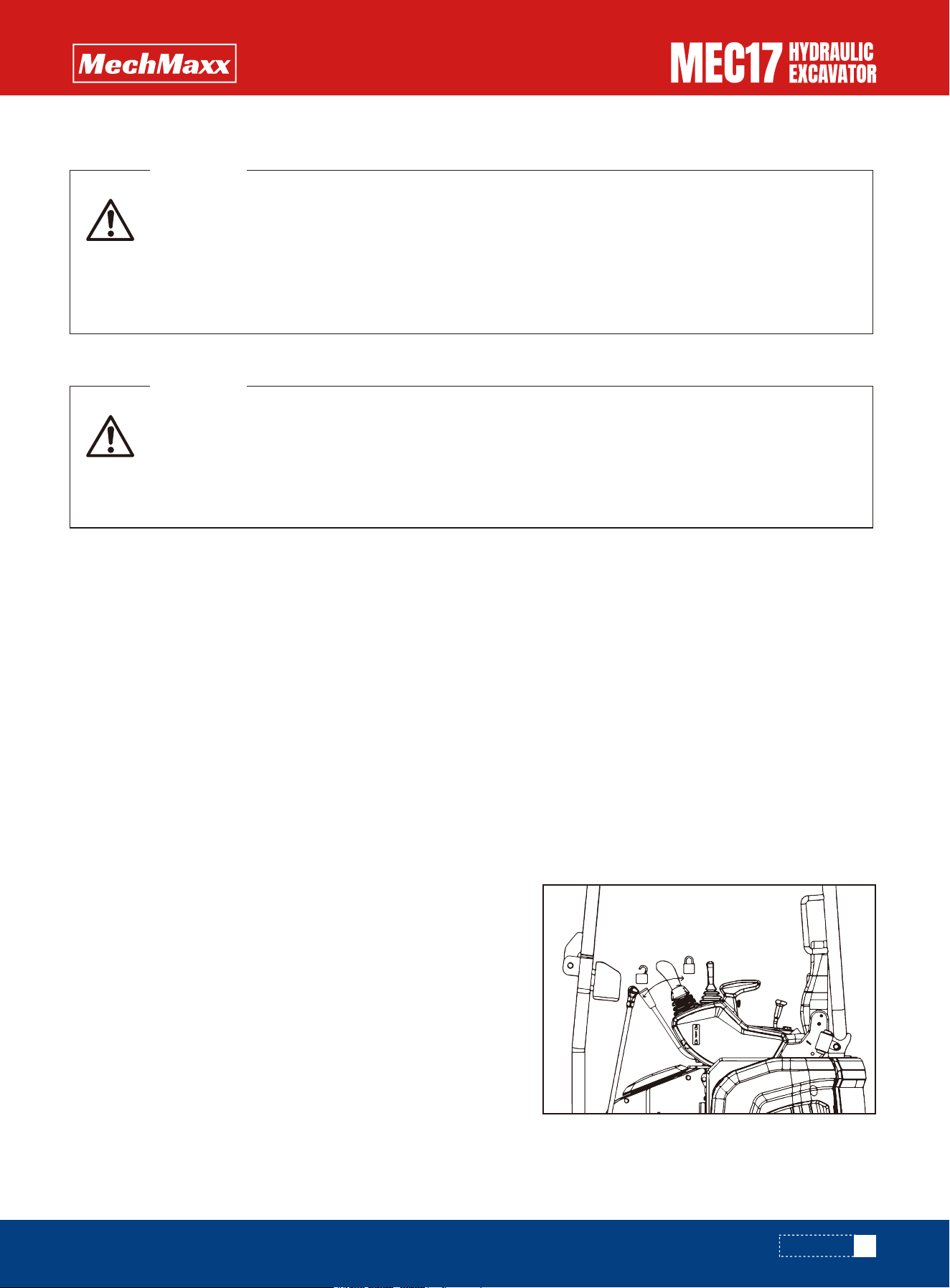
Do not start operation immediately after starting the engine. First, perform the following operations and checks.
•No operation or sudden operation of the joystick is allowed under the condition of low temperature of hydraulic oil.
Warm-up operation must be carried out first to prolong the service life of the machine.
•After starting the engine, don't make the engine accelerate suddenly until the warm-up operation is completed. Espe-
cially in cold weather, if the engine accelerates suddenly, it will emit white smoke, but this does not mean abnormal.
•Do not run the engine continuously at low or high idle speeds for more than 20 minutes.
•If it is necessary to run the engine continuously at idle speed, the engine should be loaded from time to time or run at
medium speed.
1. Turn fuel control dial to center position between the low idle and
high idle positions and run the engine at a mid-range speed about 5
minutes.
When the temperature is lower than 32°F, turn the throttle knob to
the middle and low speed position for warm-up operation.
2. Place the safety lock lever in the unlock position and raise the
bucket from the ground.
3. Slowly operate the left and right joysticks to move the bucket
cylinder and stick cylinder to the end of the stroke
IMPORTANCE
REMARK
•Run the engine at idle for 5 minutes after starting it.
•Avoid operation with heavy loads or at high speeds.
•Avoid sudden starts, sudden acceleration, unnecessary sudden stops, and sudden changes in direction.
• Emergency stop If any trouble occurs, turn the starting switch to the OFF position.
• If the work equipment is operated without carrying out the warming-up operation properly, the
reaction of the work equipment to the operation of the control lever will be slow and the work
equipment may not move as the operator intends. To prevent such problems, always be sure to
carry out the warming-up operation fully. In cold weather particularly, be extremely careful to carry
out the warming-up operation fully.
WARNING
The machine has been thoroughly adjusted and tested before shipment from the factory. However,
operating the machine under full load before breaking the machine in can adversely affect the
performance and shorten the machine life.
Be sure to break in the machine for the initial 100 hours (as indicated on the service meter).
During the running-in operation, observe the precautions required in this manual.
WARNING
57
www.mechmaxx.com
After Starting Engine
Breaking in the New Machine
Warming up operation
OPERATION
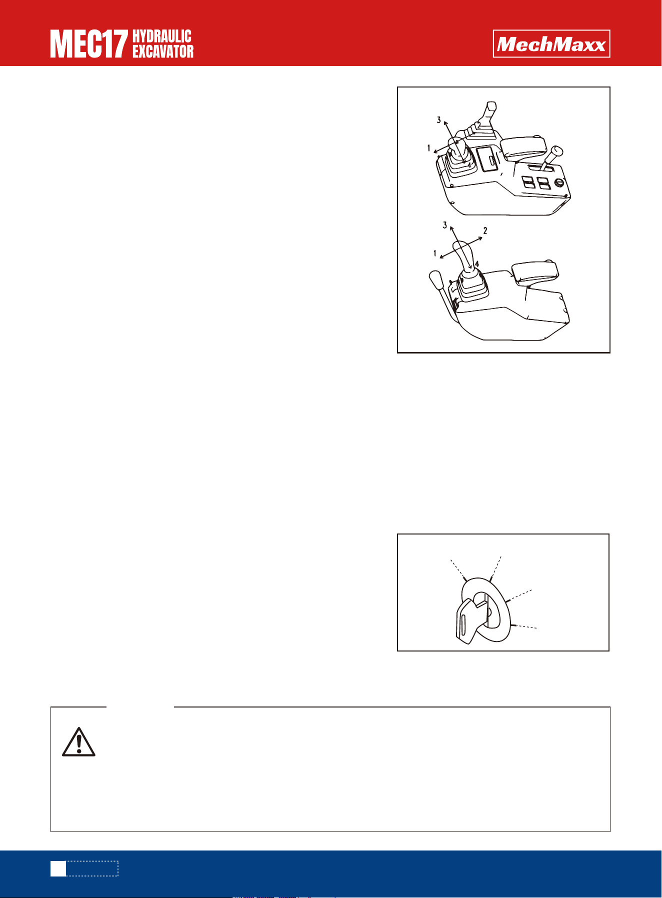
When the work equipment is retracted, take care that it does not inter-
fere with the machine body or ground.
4. Operate the bucket and the arm in turn fully for 5 minutes. (Left handle
1,2 and right handle3,4).
5. After performing the warming-up operation, check and be sure all the
gauges on machine monitor and the caution lamps are in the following
conditions:
•Fuel level monitor in the green range;
•Coolant temperature monitor in the green range;
•No alarm icon is displayed in the central area of the interface.
6. Check for abnormal exhaust gas color, noise, or vibration. If any
problem is found, contact your mechmaxx distributor.
7. Set lock lever slowly and securely to LOCK position, and make sure
that the left and right control levels are not operated for turning and
operating devices.
If the engine is stopped abruptly, service life of component parts of the engine may be considerably reduced. Do not stop
the engine abruptly except in an emergency.
If the engine has overheated, do not try to stop it abruptly but run it at medium speed to allow it to cool down gradually,
and then stop it.
1. Run the engine at low idle speed for about 5 minutes to cool down gradually.
2. Turn the key in starting switch to the OFF position and stop the engine.
3. Remove the key from starting switch.
1. Walk around the machine and check the work equipment, machine
exterior, and undercarriage, also check for any leakage of oil or coolant.
If any problems are found, repair them.
2. Fill the fuel tank.
3. Check the engine compartment for paper and debris. Clean out any
paper and debris to avoid a fire hazard.
4. Remove any mud affixed to the undercarriage.
IMPORTANCE
Matters Need Attention of Moving the Machine
IMPORTANCE
• Before operating the control lever, check the direction of the track frame. If the sprocket is at the
front, the machine moves in the opposite direction from the operation of the travel lever.
• Before starting the machine, check that the area around the machine is safe and sound the speaker.
• Do not allow anyone to enter the area around the machine.
• Clear any obstacles from the travel path.
• Here is a blind spot at the rear of the machine, so be particularly careful when traveling in reverse.
WARNING
58
www.mechmaxx.com
Stopping the Engine
Check after Shut off Engine
Machine Operation: Move and Stop
OFF
ON
START
HEAT
OPERATION
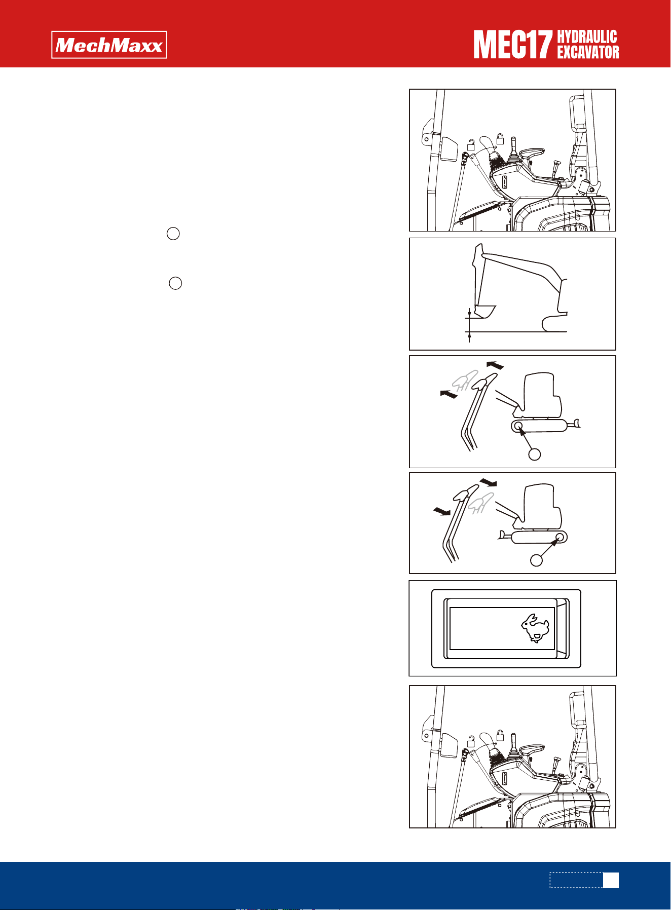
3. Operate the walking joystick according to the following steps.
Preparation before the machine moves
Pull the throttle lever back to increase the engine speed.
1. Open the safety lock lever, put away the working device and lift it
1.57-1.97 in from the ground.
2. Pull the blade control lever backward to raise the blade.
•When the driving wheel is at the back of the machine, slowly push
the left and right walking joysticks forward to move the machine.
•When the driving wheel is at the front of the machine, slowly pull
the left and right walking joysticks back to move the machine
4. Follow the steps below to switch the walking speed.
Press the walking speed switch to the high-end "rabbit gear" to switch
from low-speed walking to high-speed walking.
Press the walking speed switch to low gear to switch from high speed
to low speed.
1.Raise the safety lock lever, put away the working device and lift it
40-50cm from the ground.
2.Pull the dozer lever backward to raise the dozer.
Moving Forward
59
www.mechmaxx.com
Moving Machine Backward
A
A
1.57-1.97 in
A
A
OPERATION
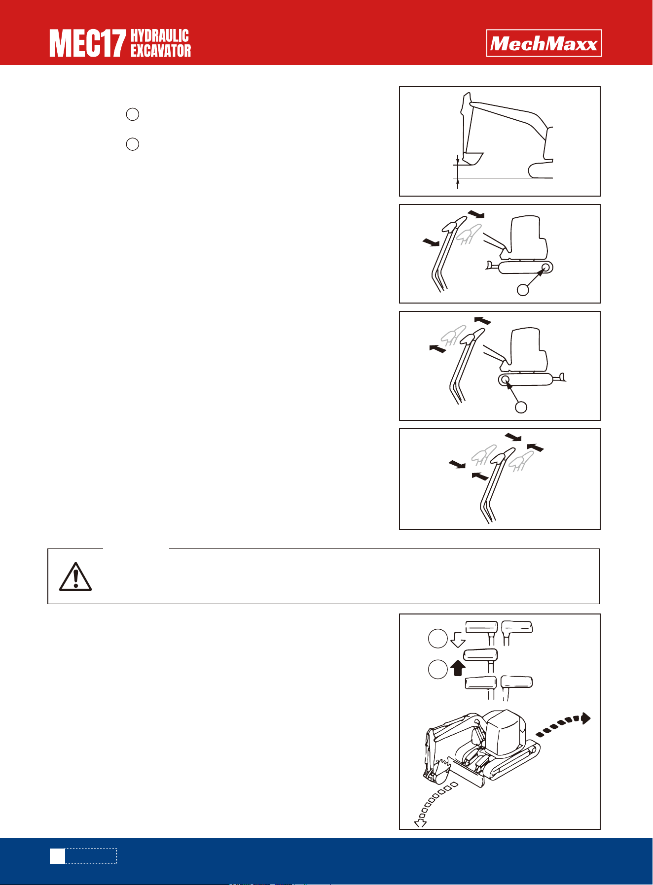
3.Operate the travel levers as follows:
•When sprocket is at the rear of the machine:
Slowly pull the joystick back to move the machine.
•When sprocket is at the front of the machine:
Slowly push the joystick forward to move the machine.
Avoid stopping suddenly. Give yourself ample room when stopping.
Put the left and right travel levers in the neutral position, then stop the
machine.
Use the travel levers to change direction.
Avoid sudden changes of direction as much as possible. Especially when
performing counter-rotation (spin turn), stop the machine before turning.
Operate two travel levers as follows.
When turning to the left, Push the right travel lever forward to turn to the
left when traveling forward; and pull it back to turn left when traveling in
reverse.
(A): Forward left turn
(B): Reverse left turn
When turning to the right, operate the left travel lever in the same way.
4.The walking speed switching mode is consistent with the "speed
forward" method.
Before operating the travel levers, check the direction of the track frame. If the sprocket is at the
rear, the machine moves in the reverse direction to the operation of the travel levers.
WARNING
60
www.mechmaxx.com
Stopping Machine
Steering the Machine
Steering
Steering the machine when stopped
REMARK
A
A
1.57-1.97 in
A
A
A
B
OPERATION
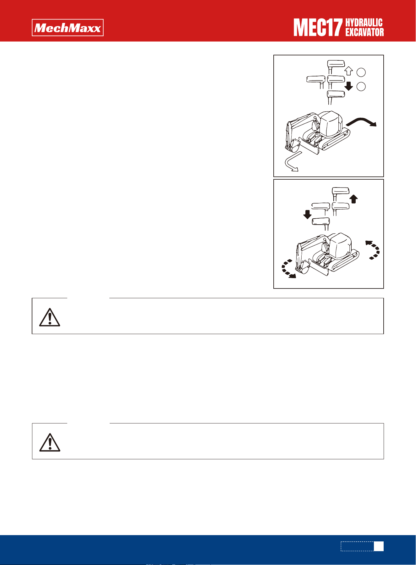
Changing direction of the machine when moving straight
When turning to the left:
If the left travel lever is returned to the neutral position, the machine will turn to
the left.
(A): Forward left turn
(B): Reverse left turn
Before operating the swing, check that the area around the machine is safe.
WARNING
This operation is only for the standard operation mode (ISO mode). For other operation modes,
please contact your dealer.
WARNING
When turning to the right, operate the right travel lever in the same way.
REMARK
•When swinging on the ramp, you should operate the engine at a low speed and operate the swing control lever at a micro
operation
•Especially in the bucket load state, should avoid sudden operation.
•When the bucket is on load, the brake of the parking brake can be released by operating the left work equipment control
lever. There will be an instant return, but this is not unusual.
Use the control levers to operate the work equipment
When the levers are released, they return to the middle position and the work equipment is held in that position.
REMARK
When using counter-rotation to turn right, pull the right travel lever back and
push the left travel lever forward.
REMARK
When rotating to the left, pull the left walking joystick back and push the
right walking joystick forward.
Counter-rotation turn (spin turn)
Swinging
Work Equipment Controls and Operations
61
www.mechmaxx.com
A
B
OPERATION
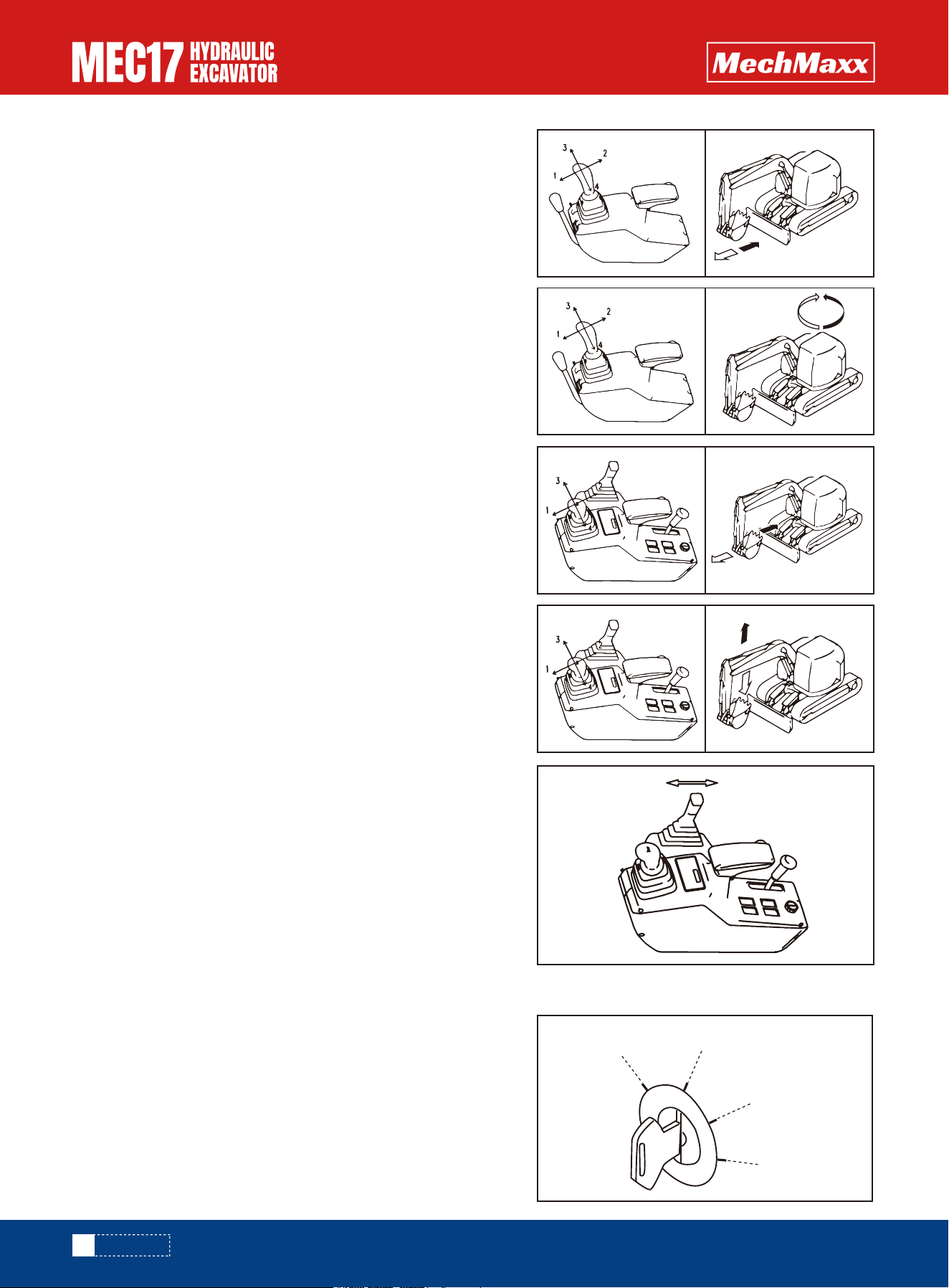
•Arm operation
Operate the left control lever forward (1) or backward (2) to control
the arm.
•Swing operation
Operate the left control lever to the left (3) or right (4) to swing the
upper structure.
•Boom operation
Operate the right control lever forward (1) or backward (2) to
operate the boom.
•Bucket operation
Operate the right control lever to the right (3) or left (4) to operate
the bucket.
•Blade operation
Move the blade lever forward or backward to operate the blade.
When the engine stops, if necessary, lower the working device to the ground or release the residual pressure in the
hydraulic circuit and do this as follows.
1.Turn the key to the ON position, lift the safety lock lever to
position.
2.Operate the required action, at this time the working device will
operate in accordance with the control handle slowly. Move the
handle back and forth a few times to release the internal pressure
fully.
3.Turn the key to the OFF position, put down the safety lock lever.
REMARK
62
www.mechmaxx.com
OFF
ON
START
HEAT
OPERATION
When carrying out hydraulic system maintenance (joint hose disassembly and replacement, etc.)
must release pressure, otherwise it will cause serious injury.
WARNING
Precautions for Lifting
•The control action requires the ability to descend under the action
of its own gravity.
•Generally the action can be able to control including a bucket arm
eversion, boom down, dozer down.
•Do not exceed the specified lifting load.
•Use wire rope that conforms to the specified standard.
•Do not carry out lifting work on slopes, soft ground, or other places where the
machine is not stable.
•It is dangerous if the raised load is too heavy and shakes. Slow down the engine
speed and operate the operating handle slowly.
•Do not start, swing, or stop the machine suddenly. There is a hazard that the
lifted load will swing.
•Do not use the work equipment or swing to pull the load in any direction. There
is danger that the hook may break and the load come off, causing the work
equipment to move suddenly and cause personal injury.
•Do not use two machines together to enhance operations, it is very dangerous.
•Do not leave the operator's seat when there is a raised load.
•Prohibited for pulling pile operation.
•It is dangerous if the raised load hits any person or structure. When swinging or
operating the work equipment, check carefully that the surrounding area is
safe.
•Do not run the machine while lifting.
•Depending on the work posture, the wire rope and rings may fall off the hook. In
order to prevent this, should pay special attention to the angle of the hook.
REMARK
Operation with Hook Bucket
63
www.mechmaxx.com
OPERATION
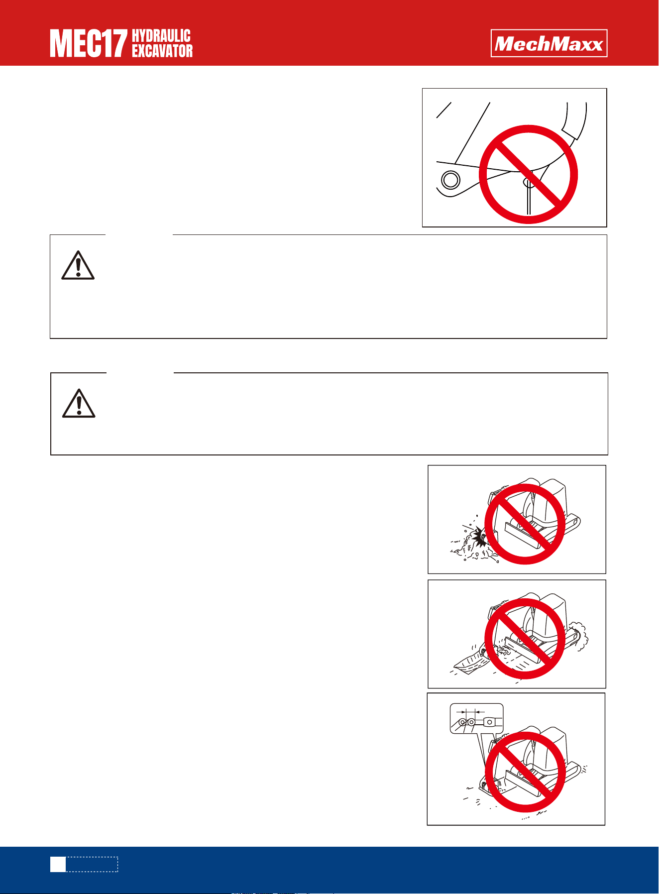
This machine bucket with hooks for auxiliary construction use, non-special lifting hooks, Profes-
sional lifting hooks must be equipped with anti-off hooks.
Any problems caused by using the machine with its own non-special hook for lifting operation have
nothing to do with our company!
If you need special hoisting hook, please contact mechmaxx Distributor.
WARNING
• If it is necessary to operate the working device while the machine is walking, be especially careful
when operating.
• If you operate any joystick when the deceleration is in effect, the engine speed will suddenly
increase, so be careful when operating.
WARNING
Please do not enter the area under the lifting weight and its surrounding.
Do not use rotational force to compact the ground or broken objects. And
during the turning process, do not dig the bucket teeth into the ground.
Doing so will damage the working device.
•When turning the bucket with a hook, be careful to avoid interference with
the boom and the body during bucket unloading.
NOTICE
Prohibited Operations
Operations Using Swing Force
Do not dig the bucket into the ground and use the travel force to carry out
excavation. This will damage the machine or work equipment.
If the work equipment is used with the cylinder rod operated to its stroke
end, and given impact by some external force, the hydraulic cylinders will
be damaged, causing personal injury. Avoid operations with the hydraulic
cylinder fully retracted or fully extended.
Operations Using Travel Force
Operations Using Stroke Ends of Hydraulic Cylinders
64
www.mechmaxx.com
OPERATION
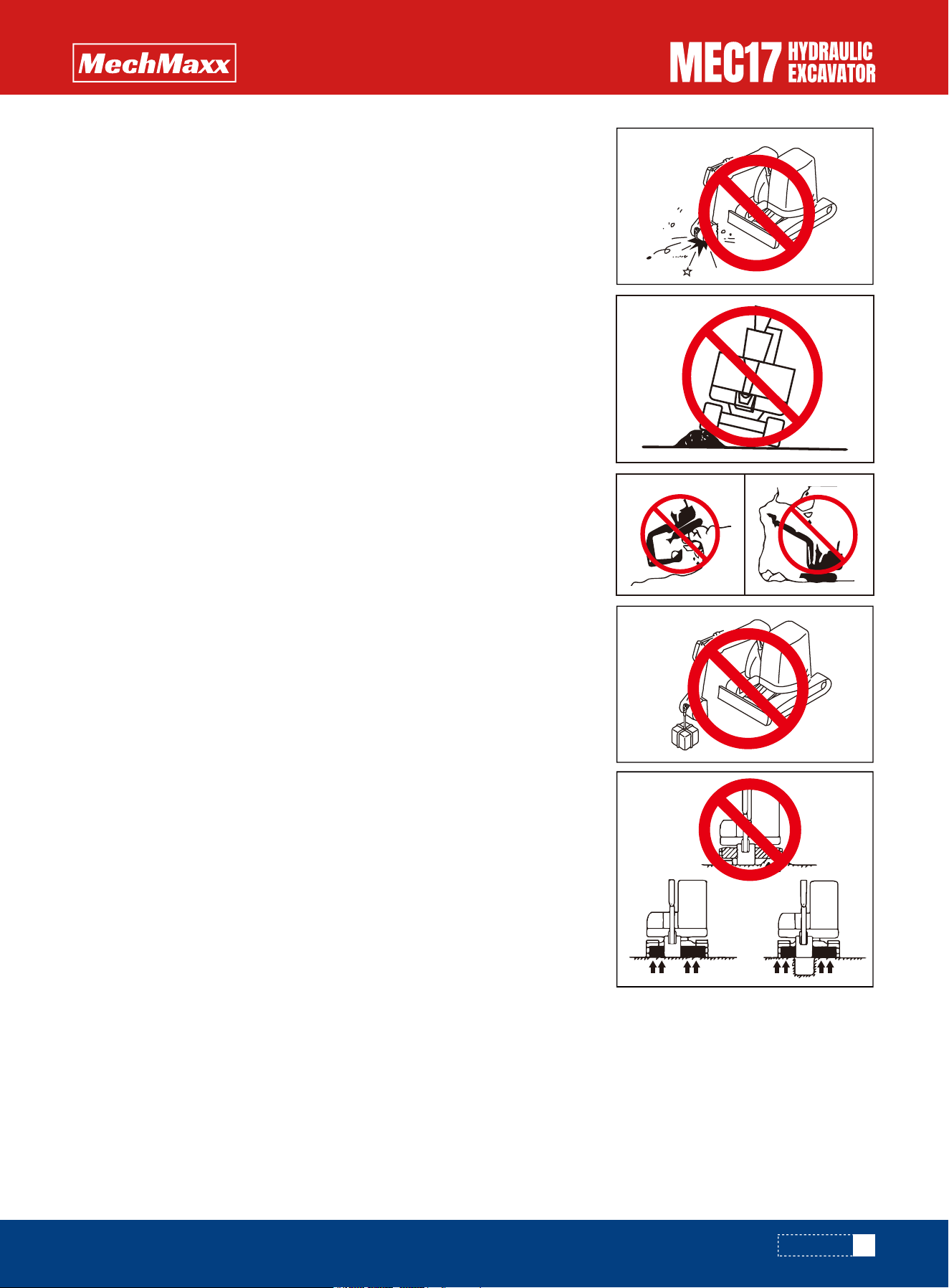
When walking on obstacles (such as gravel, tree stumps), the machine (especially the lower walking device) will
withstand a great impact, resulting in damage to the machine. Therefore, such obstacles should be removed as much as
possible and avoid walking on obstacles. As a last resort, reduce the walking speed, keep the working device close to the
ground, and make the center of the crawler cross over obstacles.
Traveling
It is better to excavate it after breaking up by some other means. This will not
only save the machine from damage but will make for better economy.
Digging Hard Rocky Ground
Use the descending force of the working device to excavate, use the descend-
ing force of the bucket as a pick, or use the bucket for impact excavation or pile
driving. Doing so will generate excessive force. In addition to causing damage
to the machine, it is also very dangerous, so do not Do this
Operations Using Bucket Dropping Force
General Operation Information
Do not use the descending force of the machine for digging. The hard rocky
ground is best broken by other methods first, and then excavated. This will not
cause damage to the machine and is more economical. Do not use the descend-
ing force of the machine for digging.
Operations Using Machine Dropping Force
It is prohibit to use this machine for lifting operations, but it is not restricted
when a special lifting hook is installed.
Refer to “Operation with Hook Bucket”.
Prohibit Lifting Operations
Do not sustain the machine with one end of the blade when using blade.
Sustain Blade on Both Sides
65
www.mechmaxx.com
OPERATION
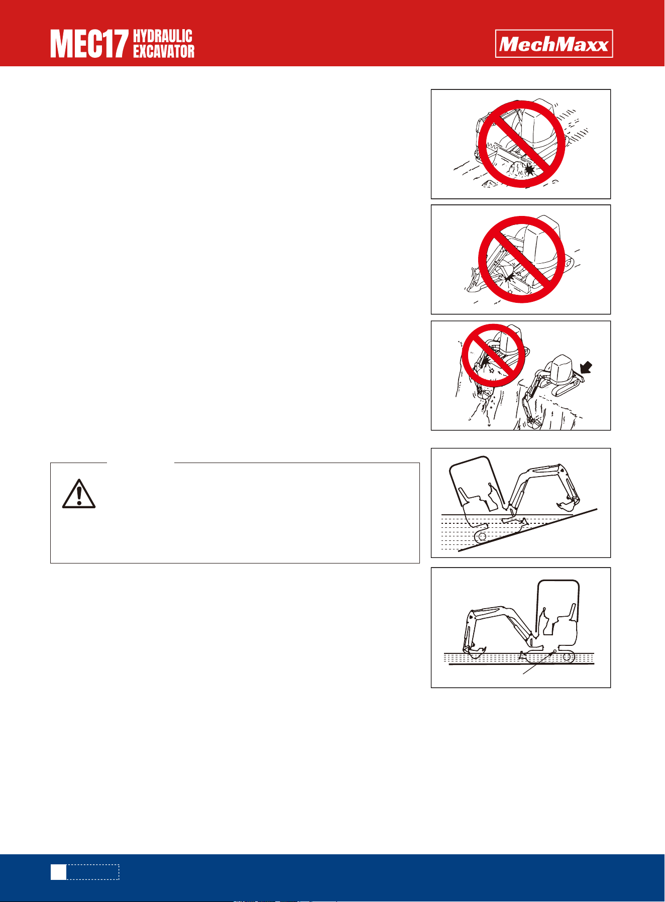
Do not given impact by some stones or road shoulder, this will premature
damage the blade or hydraulic cylinders.
Avoid Blade Impacted
Be careful not to allow the bucket to impact the blade when the work equipment
is folded in traveling or transport attitude.
Fold the Work Equipment
When the excavator is in deep excavation while the blade is at the front, be
careful not to impact the blade with the boom cylinder. In addition to the blade
must be in the front, insure put the blade placed in the rear.
Do not drive the machine in water deeper than the center of carrier roller.
Supply grease to the parts which have been under water for a long time until the
used grease is projected out of the bearings (around the bucket pin, in particu-
lar).
Blade in Backhoe Operation
When driving the machine out of water, if the angle of the
machine exceeds 15°, the rear of the upper structure will go
under water, and water will be thrown up by the radiator fan.
This may cause the fan to break.
Be extremely careful when driving the machine out of water.
WARNING
Permissible Depth of Water
66
www.mechmaxx.com
1
OPERATION
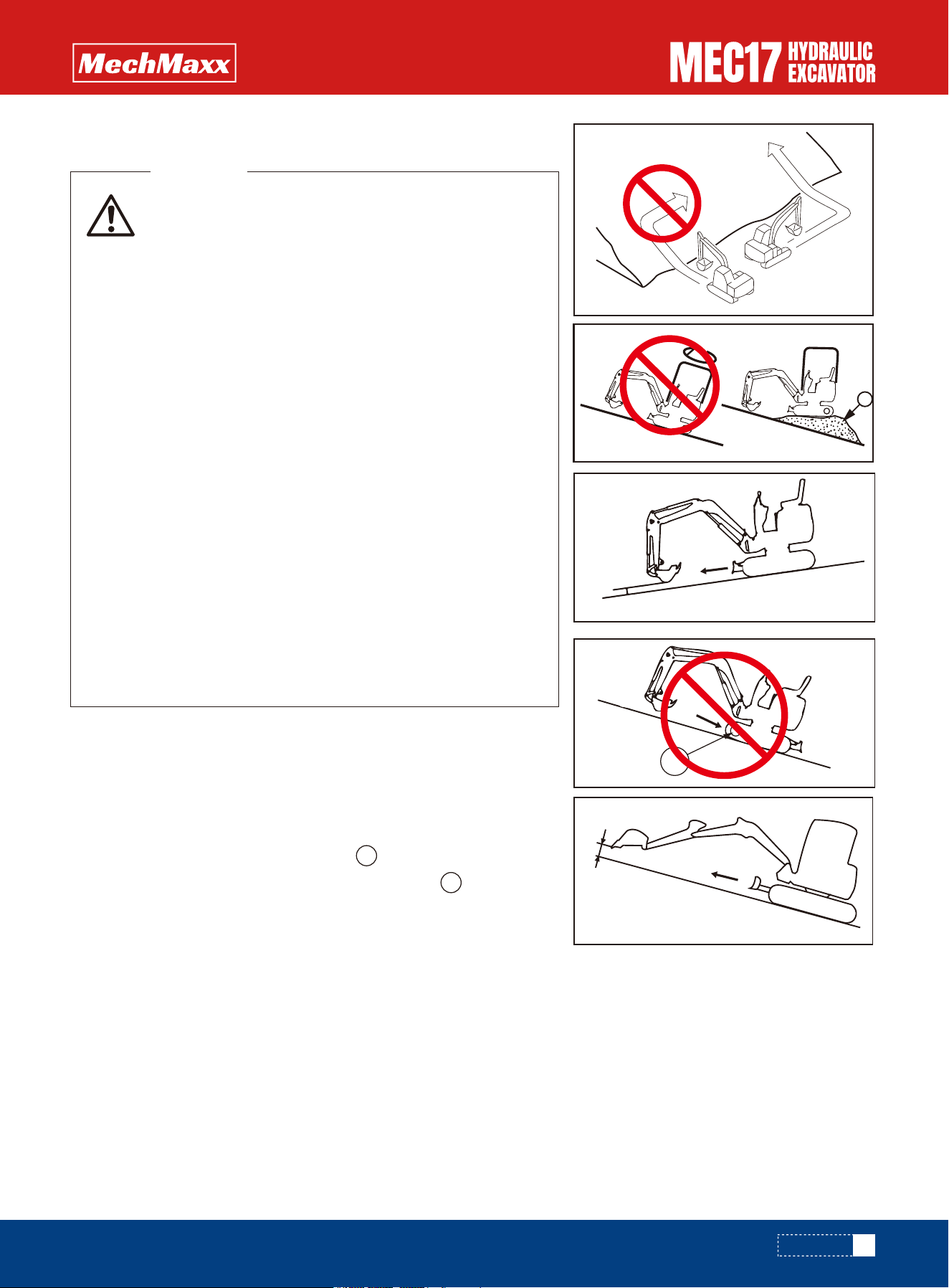
1 .When traveling down steep hills, use the travel lever and fuel control
dial to keep the travel speed low. When traveling down a steep hill of more
than 15°, set the work equipment to the posture shown in the diagram on
the right and lower the engine speed.
Put the travel lever in the middle position. This will cause the brake to be automatically applied.
2. When traveling up a steep hill of more than 15°, set the work equipment
to the posture shown in the diagram on the right.
When traveling downhill, the sprocket side in the downhill side.
If the machine goes downhill, the side of the drive wheel is on the uphill
side, the crawler tends to
It will relax and cause tooth skipping.
REMARK
Traveling Downhill
If the engine stops when traveling uphill, move the travel levers to the middle position, lower the bucket to the ground,
stop the machine, then start the engine again.
Engine Stopped on Slope
•Even if the engine is turned off on a slope, if the left working device joystick is used for turning operations, the upper
turning platform will turn due to its own weight. Therefore, turning operations must not be performed.
Notes on Slopes
• Turning or operating the work equipment when work-
ing on slopes may cause the machine to lose it
balance and turn over, so avoid such operations. It is
particularly dangerous to swing downhill when the
bucket is loaded. If such operations have to be
performed, pile soil to make a platform (A) on the
slope so the machine is kept horizontal during opera-
tion.
• Do not travel up or down steep slopes. There is a
danger that the machine may turn over.
• When traveling, raise the bucket approx. 20 to 30 cm
from the ground. Do not travel downhill in reverse.
• Never turn on slopes or travel across slopes. Always
go down to a flat place to perform these operations. It
may belonger, but it will ensure safety.
• Always operate or travel in such a way that it is possi-
ble to stop safely at any time if the machine slips or
becomes unstable.
• When traveling uphill, if the shoes slip or it is impossi-
ble to travel uphill using only the force of the tracks,
do not use the pulling force of the arm to help the
machine travel uphill. There is danger that the
machine may turn over.
WARNING
Traveling on Slopes
67
www.mechmaxx.com
1
1
0.7 to 1.1 in
0.7 to 1.1 in
1
A
OPERATION
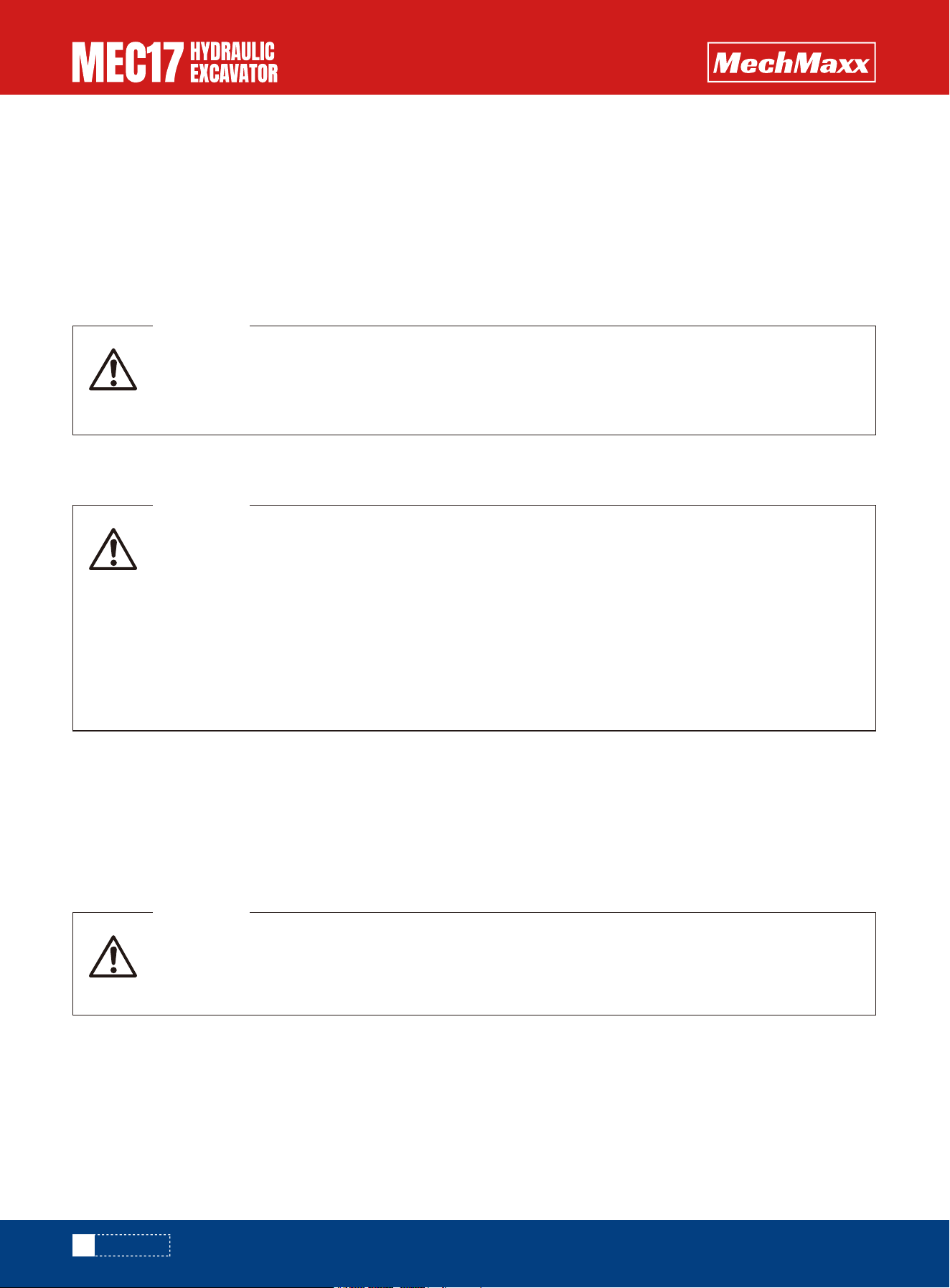
If the temperature becomes low, it becomes difficult to start the engine, and the coolant may freeze, so do as follows:
Change to fuel and oil with low viscosity for all components. For details of the specified viscosity, see “Please use the
Recommended Fuel, Oil and Coolant and Water for Dilution”.
When the ambient temperature drops, the capacity of the battery will also drop. If the battery charge ratio is low, the
battery electrolyte may freeze. Maintain the battery charge as close as possible to 100%. Insulate it against cold
temperature to ensure the machine can be started easily the next morning.
To prevent mud, water, or the undercarriage from freezing and making it impossible for the machine to move on the follow-
ing morning, observe the following precautions.
Cold Weather Operation Information
Fuel and Lubricants
Cooling System Coolant
Battery
•As the battery capacity drastically drops in low temperatures, cover or remove the battery from the machine, store the
battery in a warm place, and install it again the next morning.
For details of the antifreeze mixture when changing the coolant, see “Clean inside of Cooling System – Clean/Replace”.
• Antifreeze is toxic. Be careful not to get it into your eyes or on your skin. If it should get into your
eyes or on your skin, wash it off with large amounts of fresh water and see a doctor at once.
• Antifreeze is flammable. Do not bring any flame close. Do not smoke when handling antifreeze.
WARNING
• Performing idle-running of the tracks is dangerous, stay well away from the tracks.
• After work completion, fill the fuel tank to capacity. This minimizes moisture condensation in the
tank when the temperature drops.
WARNING
• The battery generates flammable gas. Do not bring fire or sparks near the battery.
• Battery electrolyte is dangerous. If it gets in your eyes or on your skin, wash it off with a large
amount of water and consult a doctor.
• Battery electrolyte dissolves paint. If it gets on the bodywork, wash it off immediately with water.
• If the battery electrolyte is frozen, do not charge the battery or start the engine with a different
power source. There is danger that the battery may explode.
• Battery electrolyte is toxic. Do not let it flow into drainage ditches or spray it on to the ground
surface.
WARNING
Cold Weather Operation
After Daily Work Completion
68
www.mechmaxx.com
OPERATION
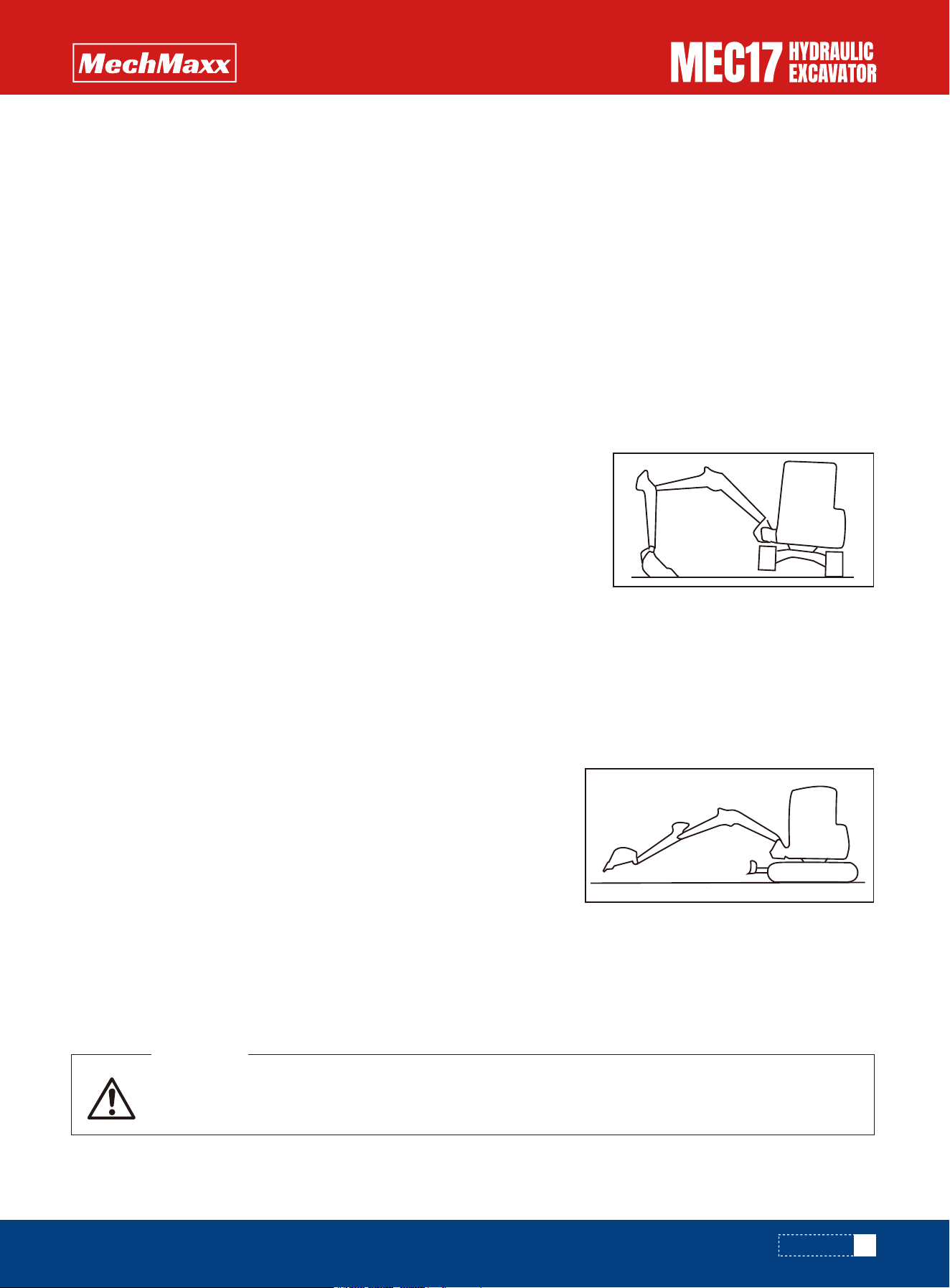
•Remove all the mud and water from the machine body. In particular, wipe the hydraulic cylinder rods clean to prevent
damage to the seal caused by mud, dirt, or drops of water on the rod from getting inside the seal.
•Park the machine on hard, dry ground.
•If this is impossible, park the machine on boards.
•The boards prevent the tracks from freezing to the ground, and allow the machine to be moved the next morning.
•Open the drain valve and drain any water collected in the fuel system to prevent it from freezing.
•After operation in water or mud, remove water from undercarriage as described below to extend undercarriage service
life.
•Clean and wash all parts, then store the machine indoors. If the machine
has to be stored outdoors, select level ground and cover the machine with
canvas.
•Completely fill the fuel tank. This prevents moisture from collecting.
•Lubricate and change the oil before storage.
•Coat the exposed portion of the hydraulic cylinder piston rod with grease.
•Set the attachment control pedal to the lock position on machines ready
for attachments.
•Set the stop valve to the LOCK position on machines ready for attach-
ments. Install the blind plugs to the elbows.
When the season changes and the weather becomes warmer, do as follows.
•Replace the fuel and oil for all parts with oil of the viscosity specified.
For details, see “Please use the Recommended Fuel, Oil and Coolant and Water
for Dilution”.
If for some reason it is not possible to use permanent type coolant, replace it
with glycol-based coolant, or if there is no coolant, must clean the cooling
system completely, and add fresh soft water.
When storing the machine (1 month or more), set the machine in the posture shown in the diagram on the right to protect
the cylinder rod.(To prevent rusting of the cylinder rod).
When putting the machine in storage for a long time (more than one month), do as follows.
1.Swing 90° with engine at low idle and bring the work equipment to the side of the track.
2.Jack up the machine until the track is raised slightly from the ground. Rotate the track under no load. Repeat this proce-
dure on both the left and right sides.
If it is necessary to perform the rust-prevention operation while the machine is indoors, open the
doors and windows to improve ventilation and prevent gas poisoning.
WARNING
After Cold Weather Season
Long Term Storage
During Storage
Before Storage
NOTICE
69
www.mechmaxx.com
OPERATION
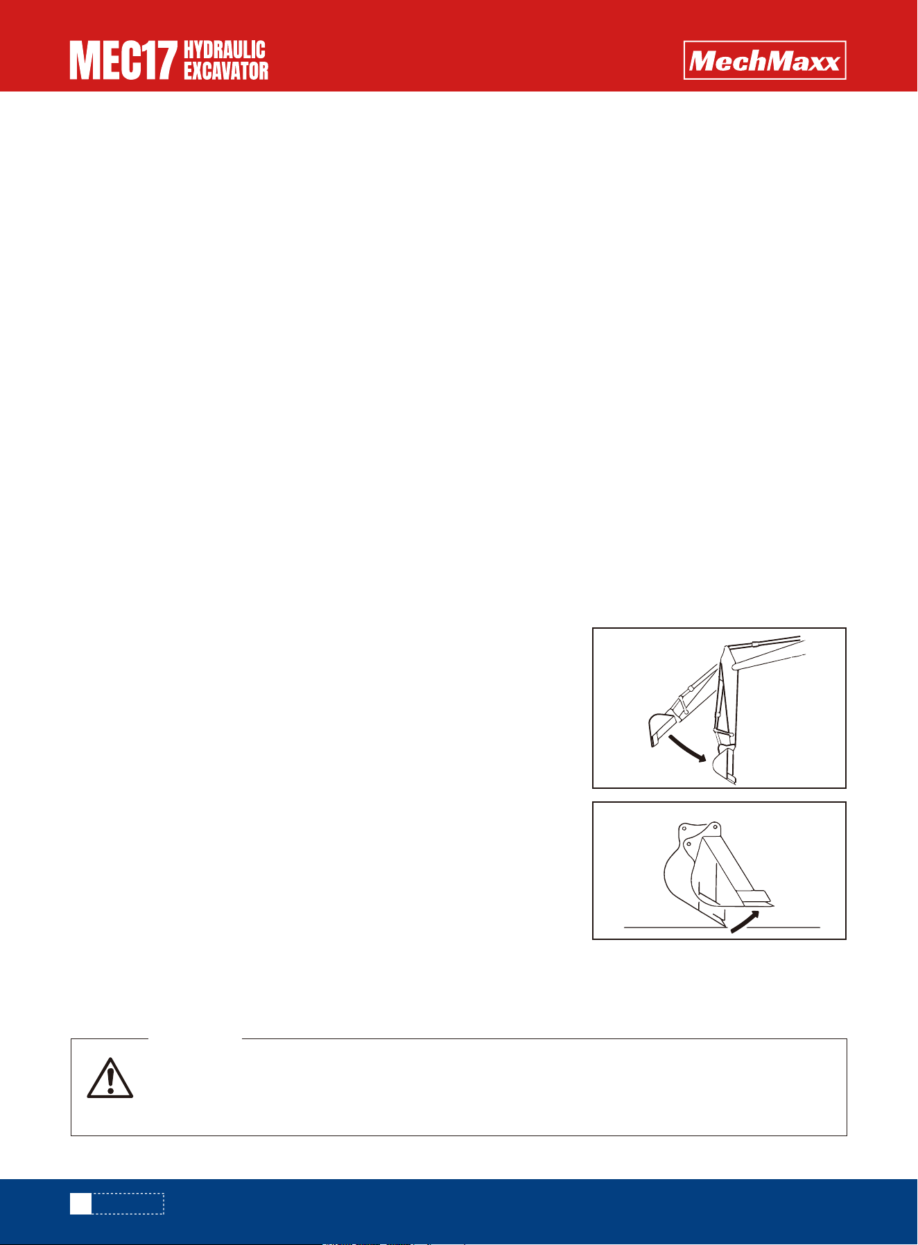
•During storage, operate and move the machine for a short distance once a month so that a new film of oil will coat
moving parts. At the same time, also charge the battery.
•When operating the work equipment, wipe off all the grease from the hydraulic cylinder rods.
•If the machine is equipped with an air conditioner, operate the air conditioner for 3 to 5 minutes once a month to
lubricate all parts of the air conditioner compressor. Always run the engine at low idle when doing this. In addition, check
the refrigerant level twice a year.
•Wipe off the grease from the hydraulic cylinder rods.
•Add oil and grease at all lubrication points.
•When the machine is stored for a long period, moisture in the air will mix with the oil. Check the oil before and after start-
ing the engine. If there is water in the oil, change all the oil.
•Turn on the battery circuit breaker. The operation method refers to "battery circuit breaker".
If the machine has been stored without carrying out the monthly rust-prevention operation, consult your mechmaxx
construction machinery distributor before using it.
When using the machine after long-term storage, do as follows before using it.
When starting the engine again after running out of fuel, fill with fuel, then bleed the air from the fuel system before start-
ing the engine.
For details, see “Air Bleeding of Fuel System”
• Always check that the wire rope used for towing has ample strength for the weight of the machine
being towed.
• Operate the machine slowly and be careful not to apply any sudden load to the wire rope.
WARNING
Note that the following phenomena are not failures:
•When the arm control lever is operated to the IN position and the work equip-
ment is lowered under no load from a high position, the arm speed will drop
momentarily when the arm is more or less at the vertical position.
•When the bucket control lever is operated to the CURL position and the work
equipment is lowered under no load from a high position, the bucket speed will
drop momentarily when the bucket teeth are more or less at the horizontal
position. The bucket or arm will fluctuate by itself during heavy-duty digging
operations.
•When starting or stopping the swing, noise will be emitted from the brake valve.
•When going down a steep slope at low speed, a noise will be emitted from the travel motor brake valve.
Phenomena that are not Failures
Towing the Machine
After Storage
Troubles and Actions
NOTICE
Running out of Fuel
70
www.mechmaxx.com
OPERATION
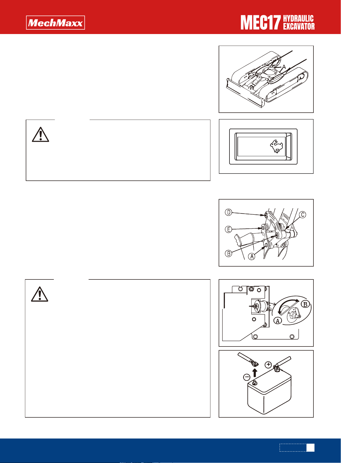
• When use A hook rings, the traction load must be light,
otherwise it is easy to damage the crawler frame.
• Hold the wire rope level and direct it straight to the track
frame.
• Move the machine slowly and be careful not to apply any
sudden load to the wire rope.
WARNING
• It is dangerous to charge a battery when mounted on a
machine. Make sure that it is dismounted before
charging.
• When checking or handling the battery, stop the engine
and turn the starting switch key to the OFF position.
• The battery generates hydrogen gas, so there is a hazard
of explosion. Do not bring lighted cigarettes near the
battery, or do anything that will cause sparks.
• When handling batteries, always wear safety glasses and
rubber gloves.
• Battery electrolyte is dilute sulfuric acid, and it will attack
your clothes and skin. If it gets on your clothes or on your
skin, immediately wash it off with a large amount of water.
If it gets in your eyes, wash it out with fresh water and
consult a doctor.
WARNING
•When carrying out digging operations in water, if the work equipment mount-
ing pin goes into the water, carry out greasing at the position
、 、 、 and every time the operation is carried out.
•For heavy-duty operations and deep digging, carry out greasing of the work
equipment mounting pins 、 、 、 and every time before operation.
After greasing, operate the boom, arm and bucket several times, then grease
again.
If the machine sinks in mud and cannot get out under its own power, or if the
drawbar pull of the excavator is being used to tow a heavy object, use a wire
rope as shown in the diagram on the right.
Place pieces of wood between wire ropes and body to prevent damage to ropes
and body.
Hold the wire rope level and direct it straight to the track frame.
There is one hole in the track frame to fit the shackle when towing light objects.
Severe Job Condition
Battery Discharges and Charges
Lightweight Towing Hole
71
www.mechmaxx.com
A B C D
A B C D E
OPERATION
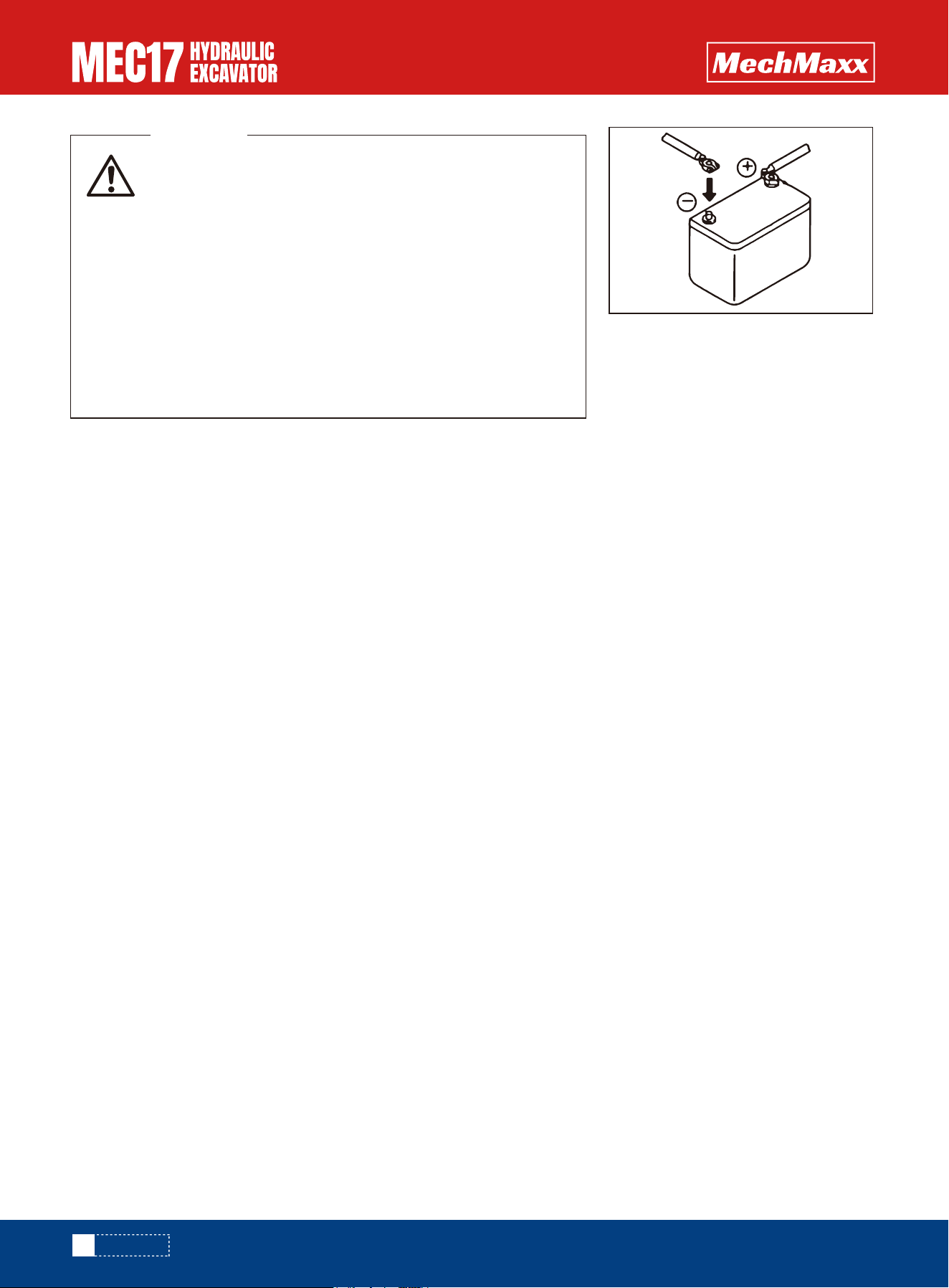
• When removing the battery, first disconnect the cable
from the ground (normally the negative (-) terminal).
When installing, install the positive (+) terminal first. If a
tool touches the positive terminal and the chassis, there is
danger that it will cause a spark, so be extremely careful.
• If the terminals are loose, there is danger that the defec-
tive contact may generate sparks that will cause an explo-
sion.
• When removing or installing the terminals, check which is
the positive(+) terminal and which is the negative (-)
terminal.
WARNING
Before cars started, the car with electric start time is too long and abnormal use, because of leakage and long car stops,
the vehicle or the vehicle charging generator failure, the battery can't normal charging battery loss caused by electricity,
battery electric eye blackened, even can't start the car. The battery need to supplement by electricity.
Check the battery status indicator (wink), power display:
Green: the battery power is enough, can normal boot excavator.
Black: deficiency of battery, the battery should be added.
White: battery needs replacement.
1.
Once inspection before charging
•Do not charge the battery if the shell burst or it leaks acid, replace the batteryafter finding out the reason.
•Do not charge the battery if its end column burst, replace the batteryafter finding out the reason.
•Do not charge the battery if the electric eye is white and replace the battery
Do not charge the inflation bulging battery caused by over-discharge or overcharge and replace the battery
•Clean the end column and remove the surface scale before charge the battery.
2.
When charging the battery we must know
•Wearing glasses.
•Maintain environmental ventilation when charging, charging under normal temperature.
•No smoking when charging, and avoid the introduction of the flame.
•After charging connection, first connect the positive attachment; Take out stitches before charging, disconnect the
cathode attachment first.
After installing the battery in place, check whether the battery is moving. If moving and re-tighten it.
•Open the left hood.
•When removing the battery, first disconnect the cable from the ground (normally the negative (-) terminal).
•If a tool touches the positive terminal and the chassis, there is danger that it will cause a spark, so be extremely careful.
•Then remove six bolts and three screws, you can remove the battery.
•When installing the battery, connect the ground cable last.
•When replacing the battery, secure it with battery hold-down.
Battery Removal and Installation
Additional Electric Battery
NOTICE
72
www.mechmaxx.com
OPERATION
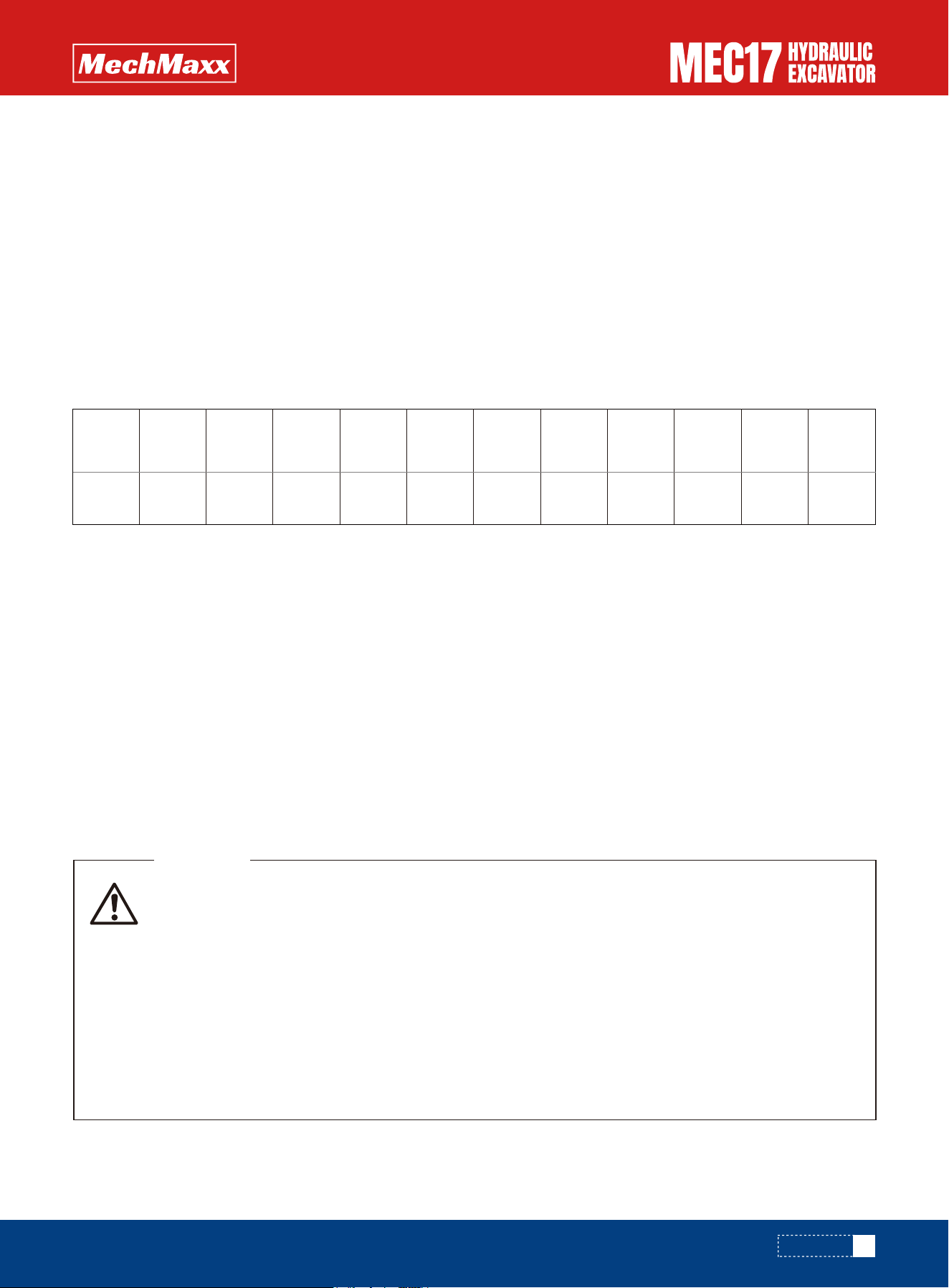
• When connecting the cables, never contact the positive (+) and negative (-) terminals.
• When starting the engine with a booster cable, always wear safety glasses.
• Be careful not to let the normal machine and problem machine contact each other. This prevents
sparks from generating near the battery which could ignite the hydrogen gas given off by the
battery. If hydrogen gas explodes, it could cause serious injury.
• Be careful not to make a mistake when connecting a booster cable. In the last connection (to the
upper structure frame), a spark will be caused, connect the cable to a spot as far away from the
battery as possible. (Avoid the work equipment, however, because it is not a good conductor)
• When removing the booster cable, exercise good care so that the booster cable clips may not
contact each other, or they contact the chassis.
WARNING
•After charging, check the color of the accumulator's eye. The electro-optic display is green, indicating that the battery
is fully charged. If the eye is black, check whether the charging connection is secured, whether the connection point is
clean, and continue to replenish the electricity until the eye appears green. For batteries whose battery voltage is less
than 11.0V, the phenomenon of battery charging out may occur in the initial stage of replenishment. Because of the
serious shortage of batteries, the proportion of sulfuric acid in the batteries has approached pure water, and the internal
resistance of the batteries is very large. With the charging of the batteries, the proportion of sulfuric acid in the batter-
ies increases, and the charging current of the batteries can gradually return to normal.
•During charging process, if the battery exhaust hole vent acid, should stop charging immediately.
•During charging process, check the battery eye color every hour. The battery is fully charged when the eye turns green,
then stop charging.
When starting the engine with a booster cable, do as follows:
Connecting and Disconnecting Booster Cables
Starting Engine with Booster Cables
73
www.mechmaxx.com
Battery
voltage
Charging
time
12.55~
12.45V
2 hours 3 hours 4 hours 5 hours 6 hours 7 hours 8 hours 9 hours 10 hours 12 hours 14 hours
12.45~
12.35V
12.35~
12.20V
12.20~
12.05V
12.05~
11.95V
11.95~
11.80V
11.80~
11.65V
11.65~
11.50V
11.50~
11.30V
11.30~
11.00V
bellow
11.00V
3.
Battery charging
•Connect the positive (+) charger clip of the charger to the positive (+) terminal of the battery, then connect the nega-
tive (-) charger clip of the charger to the negative (-) terminal of the battery.
•Make sure the battery is clean and the charging circuit is well connected.
•Recommended use constant voltage 16.0 volts (maximum can not exceed 16.2 volts, the charging current does not
exceed 25A) charger to charge battery until the electric eye turns green. The battery is fully charged when the eye turns
green.
•IF there is not a constant voltage way to charge, according to the following specifications constant current charging:
•Charging current(A)=C20/10.(C20 --- 20 hours rate capacity)
Note:
If more than one battery is charged in parallel, the current values are summed.
Charging time and battery voltage corresponding relationship (reference)
OPERATION
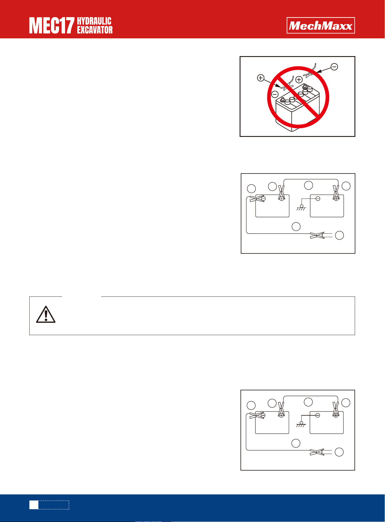
Always check that the lock lever is set to the LOCK position, regardless of whether the machine is
working normally or has failed. Check also that all the control levers are in the HOLD or neutral posi-
tion.
WARNING
1. Make sure the clips are firmly connected to the battery terminals.
2. Start engine of the normal machine and run it at high idle speed.
3. Turn the starting switch of the problem machine to the START position and start the engine.If the engine doesn't start
at first, try again after 2 minutes or so.
After the engine has started, disconnect booster cables in the reverse
order in which they were connected.
1.Remove one clip of booster cable (B) from the revolving frame of the
problem machine.
2.Remove the clip of booster cable (B) from the negative (-) terminal of
battery on the normal machine.
3.Remove the clip of booster cable (A) from the positive (+) terminal of
battery on the normal machine.
Remove the clip of booster cable (A) from the positive (+) terminal of
battery on the problem machine.
•The starting system for this machine uses 12V. For the normal machine,
also use a 12V battery.
•The size of the booster cable and clip should be suitable for the battery
size.
•The battery of the normal machine must be the same capacity as that of
the engine to be started.
•Check the cables and clips for damage or corrosion.
•Make sure that the cables and clips are firmly connected.
•Check that the lock levers and parking brake levers of both machines are
in the LOCK position.
•Check that each lever is in the NEUTRAL position.
Keep the starting switch of the normal machine and problem machine in
the OFF position.
1.Connect the booster cable as follows, in the order of the numbers
marked in the diagram.
2.Connect the clip of booster cable (A) to the positive (+) terminal of
battery on the problem machine.
3.Connect the clip at the other end of booster cable (A) to the positive (+)
terminal of battery on the normal machine.
4.Connect the clip of booster cable (B) to the negative (-) terminal of
battery on the normal machine.Connect the other clip of booster cable (B)
to the revolving frame of the problem machine.
NOTICE
Starting the Engine
Booster Cable Disconnection
Booster Cable Connection
74
www.mechmaxx.com
A
Normal machine Abnormal machine
Engine Cylinder Block of Abnormal Machine
B
1
2
3
4
A
Normal machine Abnormal machine
Engine Cylinder Block of Abnormal Machine
B
1
2
3
4
OPERATION

Speed of travel, swing, boom,
arm, bucket is low
Pump generates abnormal noise
Excessive rise in hydraulic oil temperature
Track comes off
Abnormal wear of sprocket
Boom rises slowly, does not rise
Lack of hydraulic oil
Clogged element in hydraulic
Loosen fan belt
Dirty oil cooler
Lack of hydraulic oil
Track too loose
Lack of hydraulic oil
Add oil to specified level, see
Maintenance
Clean, see Maintenance
Check and adjust fan belt tension,
see Maintenance
Clean, see Maintenance
Add oil to specified level,
see Maintenance
Adjust track tension, see
Maintenance
Add oil to specified level, see
Maintenance
Problem Main causes Remedy
•The starting system for this machine uses 12V. For the normal machine,
also use a 12V battery.
•The size of the booster cable and clip should be suitable for the battery
size.
•The battery of the normal machine must be the same capacity as that of
the engine to be started.
•Check the cables and clips for damage or corrosion.
•Make sure that the cables and clips are firmly connected.
•Check that the lock levers and parking brake levers of both machines are
in the LOCK position.
•Check that each lever is in the NEUTRAL position.
•In case of problems or causes which are not listed below, contact your mechmaxx distributor.
Others Malfunction
Chassis
75
www.mechmaxx.com
OPERATION

•The starting system for this machine uses 12V. For the normal machine,
also use a 12V battery.
•The size of the booster cable and clip should be suitable for the battery
size.
•The battery of the normal machine must be the same capacity as that of
the engine to be started.
•Check the cables and clips for damage or corrosion.
•Make sure that the cables and clips are firmly connected.
•Check that the lock levers and parking brake levers of both machines are
in the LOCK position.
•Check that each lever is in the NEUTRAL position.
Even if the engine is running at high
speed, the lighting is not bright.
Lead failure
Belt tension adjustment error
AC generator fault
Lead failure
Lead failure
Starting motor fault
Battery charging problem
Safety relay fault
Battery charging problem
Starting motor fault
Battery charging problem
Starting motor fault
Lead failure
Battery charging problem
AC generator fault
(Check and repair the loose
terminals.)
(replace)
(Check and repair)
(Check and repair)
(replace)
Charge
(replace)
Charge
(replace)
Charge
(replace)
Check and repair
Charge
(replace)
Adjust fan belt tension, see every
1000 hours of maintenance
When the engine is running, the lights
flicker
Even when the engine is running, the
charge monitor does not go out.
When the starting switch is switched to
ON, the starting motor does not work.
Starting motor pinion to keep running
Start motor slowly rotating engine
Before starting the engine, motor
starting off
AC generator generates abnormal noise
Hitch Main cause Resolvent
•When dealing with these projects, please contact the mechmaxx dealer.
•If there are not listed in the table below the fault or reason, please contact the dealer for repair.
Electrical System
76
www.mechmaxx.com
OPERATION

•The starting system for this machine uses 12V. For the normal machine,
also use a 12V battery.
•The size of the booster cable and clip should be suitable for the battery
size.
•The battery of the normal machine must be the same capacity as that of
the engine to be started.
•Check the cables and clips for damage or corrosion.
•Make sure that the cables and clips are firmly connected.
•Check that the lock levers and parking brake levers of both machines are
in the LOCK position.
•Check that each lever is in the NEUTRAL position.
Engine oil pressure
monitor lights up
• Engine oil pan oil level is low (sucking in air)
• Clogged oil filter cartridge
• Defective tightening of oil pipe, pipe joint,
oil leakage from damaged point
• Defective engine oil pressure sensor
• Defective monitor
• Coolant level low, leakage of water
• Dirt or scale accumulated in cooling system
• Clogged radiator fins or damaged fins
• Defective thermostat
• Loose radiator filler cap (high-altitude
operations)
• Defective water level sensor
• Lack of fuel
• Air in fuel system
• Defective fuel injection pump or defective
nozzle
• Starting motor cranks engine sluggishly
• Engine pre-heating monitor does not light up
• Defective compression
• Too much oil in oil pan
• Improper fuel
• Start the engine suddenly accelerated in
the cold days
• Clogged air cleaner element
• Defective nozzle
• Defective compression
• Defective nozzle
• Set oil to specified level, see
CHECK BEFORE STARTING
• Change to specified fuel
• Avoid suddenly acceleration
before the warm-up operation is
completed
• Clean or replace
• ( Replace nozzle)
• ( See defective compression
above)
• (Replace nozzle)
• Add fuel, see CHECK BEFORE
STARTING
• Repair place where air is sucked in
• ( Replace pump or nozzle)
• See ELECTRICAL SYSTEM
• See ELECTRICAL SYSTEM
• ( Adjust valve clearance)
• Defective thermostat
• Add oil to specified level, see
CHECK BEFORE STARTING
• Replace cartridge, see EVERY
500 HOURS SERVICE
• ( Check, repair)
• ( Replace)
• Check, add coolant, repair
• Change coolant, flush inside of
cooling system,
• ( Replace thermostat)
• Tighten cap or replace packing
• ( Replace sensor)
• ( Replace thermostat)
Steam spurts out from
top of radiator (pressure
valve)
Even after long hours of
operation,radiator coolant
level monitor lights up
Engine does not start
when starting motor is
turned
Exhaust gas is white or
blue
Combustion noise
occasionally make
breathing sound
Exhaust gas occasionally
turns black
Radiator coolant level
monitor lights up
Problem Main causes Remedy
•Always contact your mechmaxx distributor when dealing with these items.
•In cases of problems or causes which are not listed below, contact your mechmaxx distributor for repairs.
Engine
77
www.mechmaxx.com
OPERATION

•The starting system for this machine uses 12V. For the normal machine,
also use a 12V battery.
•The size of the booster cable and clip should be suitable for the battery
size.
•The battery of the normal machine must be the same capacity as that of
the engine to be started.
•Check the cables and clips for damage or corrosion.
•Make sure that the cables and clips are firmly connected.
•Check that the lock levers and parking brake levers of both machines are
in the LOCK position.
•Check that each lever is in the NEUTRAL position.
Abnormal noise
generated(combustion
or mechanical)
• Low-grade fuel being used
• Overheating
• Damage inside muffler
• Excessive valve clearance
• Clogged fuel cleaner element
• Defective engine or defective fuel line
• Change to specified fuel
• Refer to " Radiator coolant level
monitor lights up" as above
• Replace muffler
• ( Adjust valve clearance)
• Replace
• ( Check, repair)
The engine stops when
operating
Problem Main causes Remedy
78
www.mechmaxx.com
OPERATION

Do not perform any inspection and maintenance operation that is not found in this manual.
•Cut off power. Wait for approx. one minute after turning off the engine starting switch key, and then disconnect the
negative (-) terminal of the battery.
•Do not apply more than 200 V continuously.
•Connect grounding cable within 1 m (3.3 ft) of the area to be welded. If grounding cable is connected near instruments,
connectors, etc., the instruments may malfunction.
•If a seal or bearing happens to come between the part being welded and grounding point, change the grounding point to
avoid such parts.
•When opening inspection windows or the oil filler port of the tank to carry out inspection, be careful not to drop nuts,
bolts or tools inside the machine.
•If such things are dropped inside the machine, it may cause damage and/or malfunction of the machine, and will lead to
failure. If you drop anything inside the machine, always remove it immediately.
•Do not put unnecessary things in your pockets. Carry only things which are necessary for inspection.
Do not use the area around the work equipment pins or the hydraulic cylinders as the grounding point.
Service Meter Reading
Check the service meter reading every day to see if the time has come for any necessary maintenance to be performed.
Fresh and Clean Lubricants
Use clean oil and grease. Also, keep the containers of the oil and grease clean. Keep foreign materials away from oil and
grease.
Check Drained Oil and Used Filter
After oil is changed or filters are replaced, check the old oil and filters for metal particles and foreign materials. If large
quantity of metal particles or foreign materials are found, always report to the person in charge, and carry out suitable
action.
Fuel Strainer
If your machine is equipped with a fuel strainer, do not remove it while fueling.
NOTE
Do not Drop Things Inside Machine
When working at dusty worksites, do as follows:
•Clean the radiator fins and other parts of the heat exchange equipment more frequently, and take care not to let the fins
become clogged.
•Replace the fuel filter more frequently.
•Clean electrical components, especially the starting motor and alternator, to avoid accumulation of dust.
Dusty Jobsite
Please read and make sure that you understand the SAFETY section before reading this section.
WARNING
•The starting system for this machine uses 12V. For the normal machine,
also use a 12V battery.
•The size of the booster cable and clip should be suitable for the battery
size.
•The battery of the normal machine must be the same capacity as that of
the engine to be started.
•Check the cables and clips for damage or corrosion.
•Make sure that the cables and clips are firmly connected.
•Check that the lock levers and parking brake levers of both machines are
in the LOCK position.
•Check that each lever is in the NEUTRAL position.
Maintenance Information
Welding Instructions
79
www.mechmaxx.com
MAINTENANCE
MAINTENANCE

•When checking and replacing the oil or filters, move the machine to a place where there is no dust and take care
•To prevent dust from entering the system.
If a different brand or grade of oil has to be added, drain the old oil and replace all the oil with the new brand or grade of
oil. Never mix different brand or grade of oil.
Avoid Mixing Lubricants
Lock inspection cover securely into position with the lock bar. If inspection or maintenance is performed with inspection
cover not locked in position, there is a danger that it may be suddenly blow shut by the wind and cause injury to the
worker.
Locking the Inspection Covers
When hydraulic equipment has been repaired or replaced, or the hydraulic piping has been removed and installed again,
the air must be bled from the circuit.
If you forget to perform the checks after inspection and maintenance, unexpected problems may occur, and this may lead
to serious injury or property damage. Always do the following:
Checks after operation (with engine stopped)
•Have any inspection and maintenance points been forgotten?
•Have all inspection and maintenance items been performed correctly?
•Have any tools or parts been dropped inside the machine? It is particularly dangerous if parts are dropped inside the
machine and get caught in the lever linkage mechanism.
•Are there any leakages of coolant or oil? Have all nuts and bolts been tightened?
Checks when operating engine
•For details of the checks when operating the engine, see "Maintenance of the Engine" and pay careful attention to
safety.
•Are the inspection and maintenance items working properly? Is there any leakage of fuel or oil when the engine speed is
raised?
Hydraulic System - Air Bleeding
•When removing parts at locations where there are O-rings or gasket seals, clean the mounting surface, and replace with
new parts. When doing this, be careful not to forget to assemble the O-rings and gaskets.
•When installing the hoses, do not twist them or bend them sharply. If they are installed so, their service life will be short-
ened extremely and they may be damaged.
Hydraulic Hose Installation
Checks After Inspection and Maintenance Works
•The starting system for this machine uses 12V. For the normal machine,
also use a 12V battery.
•The size of the booster cable and clip should be suitable for the battery
size.
•The battery of the normal machine must be the same capacity as that of
the engine to be started.
•Check the cables and clips for damage or corrosion.
•Make sure that the cables and clips are firmly connected.
•Check that the lock levers and parking brake levers of both machines are
in the LOCK position.
•Check that each lever is in the NEUTRAL position.
•Oil is used in the engine and hydraulic equipment under extremely severe conditions (high temperature, high pressure),
and deteriorates with use.
•Always use oil that matches the grade and maximum and minimum ambient temperatures recommended in the Opera-
tor’s Manual. Even if the oil is not dirty, always change the oil at the specified interval.
•Oil corresponds to blood in the human body, always be careful when handling it to prevent any impurities (water, metal
particles, dirt, etc.) from getting in. When storing or adding oil, take special care not to let any impurities in.
•Never mix oils of different grades or brands.
•Always add the specified amount of oil. Having too much oil or too little oil are both causes of problems.
•If the oil in the work equipment is not clear, there is probably water or air getting into the circuit. In such cases, please
contact your mechmaxx distributor.
Lubricants, Fuels and Coolants
Lubricants
80
www.mechmaxx.com
MAINTENANCE

•When changing the oil, always replace the related filters at the same time.
•We recommend you have an analysis made of the oil periodically to check the condition of the machine.
•When using commercially available oil, it may be necessary to reduce the oil change interval.
•When diluting the antifreeze coolant, use distilled water or tap water (soft water).Natural water, such as a river water
or well water (hard water), contains large amounts of minerals (calcium, magnesium, etc.), and this makes it easier for
scale to form inside the engine or radiator. Once scale is deposited inside the engine or radiator, it is extremely difficult
to remove. It also causes overheating due to poor heat exchange.
•When using antifreeze, always observe the precautions given in the Operation and Maintenance Manual.
•Antifreeze coolant is flammable, so be sure to keep it away from flame.
•The ratio of coolant to water differs according to the ambient temperature.
•If the engine overheats, wait for the engine to cool before adding coolant.
•If the coolant level is low, it will cause overheating, and will also cause problems with corrosion due to air entering the
coolant.
•The fuel pump is a precision instrument, and if fuel containing water or dirt is used, it cannot work properly.
•Be extremely careful not to let impurities get in when storing or adding fuel.
•Always use the fuel specified for the temperature in the Operator’s Manual.
•If the fuel is used at temperatures lower than the specified temperature (particularly at temperatures below -15°C
(5°F), the fuel will solidify.
•To prevent moisture in the air from condensing into water in the fuel tank, fill the fuel tank at the end of each day's work.
•Before starting the engine, or when 10 minutes have passed after adding fuel, drain the sediment and water from the
fuel tank.
•If the engine runs out of fuel, or if the filters have been replaced, it is necessary to bleed the air from the circuit.
•Grease is used to prevent seizure and noises at the joints.
•This construction equipment is used under heavy-duty conditions. Always use the recommended grease and follow the
change intervals and recommended ambient temperatures given in this Operator’s Manual.
•The nipples not included in the maintenance section are nipples for overhaul, so they do not need grease. If any part
becomes stiff after being used for long time, add grease
•If any part becomes stiff after being used for long time, add grease.
•Always wipe off all of the old grease that is pushed out when greasing.
•Always wipe off all of the old grease that is pushed out when greasing.
•Be particularly careful to wipe off the old grease in places where sand or dirt sticking in the grease would cause wear of
the rotating parts.
•Keep indoors to prevent any water, dirt, or other impurities from getting in.
•When keeping drum cans for a long period, put the drum on its side so that the filler port of the drums is at the side to
prevent moisture from being sucked in.
•If drums have to be stored outside, cover them with a waterproof sheet or take other measures to protect them.
•To prevent any change in quality during long-term storage, be sure to use in the order of first in - first out (use the oldest
oil or fuel first).
•The starting system for this machine uses 12V. For the normal machine,
also use a 12V battery.
•The size of the booster cable and clip should be suitable for the battery
size.
•The battery of the normal machine must be the same capacity as that of
the engine to be started.
•Check the cables and clips for damage or corrosion.
•Make sure that the cables and clips are firmly connected.
•Check that the lock levers and parking brake levers of both machines are
in the LOCK position.
•Check that each lever is in the NEUTRAL position.
Coolant of the cooling system
Fuel
Storing Oil and Fuel
Grease
81
www.mechmaxx.com
MAINTENANCE

•Filters are extremely important safety parts. They prevent impurities in the fuel and air circuits from entering important
equipment and causing problems.
Replace all filters periodically. For details, refer to the operation and maintenance manual.
•However, when working in severe conditions, replace the filters at shorter intervals according to the oil and fuel (sulfur
content) being used.
•Never try to clean the filters (cartridge type) and use them again. Always replace with new filters.
•When replacing oil filters, check if any metal particles are attached to the old filter. If any metal particles are found,
contact your mechmaxx distributor.
•Do not open packs of spare filters until just before they are to be used.
•It is extremely dangerous if the electrical equipment becomes wet or the covering of the wiring is damaged. This will
cause an electrical short circuit and may lead to malfunction of the machine. Do not wash the inside of the operator's
cab with water. When washing the machine, be careful not to let water get into the electrical components.
•Service relating to the electric system is checking fan belt tension, checking damage or wear to the fan belt and check-
ing battery fluid level.
•External electron-magnetic interference may cause malfunction of the control system controller, before installing a
radio receiver or other wireless equipment, contact your mechmaxx distributor.
•When working at the seashore, carefully clean the electric system to prevent corrosion.
•When installing electrical equipment, connect it to the special power source connector.
•Do not connect the optional power source to the fuse, starting switch, or battery relay.
•The starting system for this machine uses 12V. For the normal machine,
also use a 12V battery.
•The size of the booster cable and clip should be suitable for the battery
size.
•The battery of the normal machine must be the same capacity as that of
the engine to be started.
•Check the cables and clips for damage or corrosion.
•Make sure that the cables and clips are firmly connected.
•Check that the lock levers and parking brake levers of both machines are
in the LOCK position.
•Check that each lever is in the NEUTRAL position.
Filters
Electric System Maintenance
82
www.mechmaxx.com
MAINTENANCE
•The hydraulic device is in high temperature during and after operation.In addition, due to the high pressure in the process
of operation, the following matters should be noted during the inspection and maintenance of the hydraulic device:
•Leave the machine in a flat place so that the bucket is completely lowered to the ground, and check and maintain it
without pressure applied to the oil path of the cylinder.
•Be sure to stop the engine
•After the operation, the hydraulic oil and lubricating oil are still in the state of high temperature and high pressure, and
the maintenance can only be carried out after the oil temperature of each part drops.
•Sometimes even though the temperature has dropped, the internal pressure is still there. The internal pressure should
be released before maintenance. At the same time, slowly loosen the screw plug, screw and screw loose pipe joint, avoid
the front of the body, and remove it while releasing internal pressure.
•During the inspection and maintenance of the hydraulic oil circuit, please be sure to discharge the air in the hydraulic
tank and release the internal pressure.
•Inspection and maintenance includes inspection of hydraulic oil level, filter and replacement of hydraulic oil. When
removing the high pressure hose, be careful not to damage the o-ring. If there is any damage, please replace it.
•When replacing and cleaning the filter element and screen of the hydraulic oil filter, when repairing, replacing and remov-
ing the hydraulic piping of the hydraulic device, air shall be discharged from the oil path.
Maintenance of Hydraulic System

•The starting system for this machine uses 12V. For the normal machine,
also use a 12V battery.
•The size of the booster cable and clip should be suitable for the battery
size.
•The battery of the normal machine must be the same capacity as that of
the engine to be started.
•Check the cables and clips for damage or corrosion.
•Make sure that the cables and clips are firmly connected.
•Check that the lock levers and parking brake levers of both machines are
in the LOCK position.
•Check that each lever is in the NEUTRAL position.
83
www.mechmaxx.com
MAINTENANCE
•Failure to use the recommended product can result in shortened life and excessive wear of engines, drivetrains, cooling
systems and other components.
•Select and use the oils and grades recommended in the table below according to ambient temperature.
•Under 32°F when you start the engine, even if the temperature has risen to more than 32°F temperature, also be sure
to use more than the recommended grade engine oil.
•When refueling, the filter should be removed from the refueling port first, and then be cleaned with clean diesel oil and
put back to the refueling port before refueling.
•The addition of oil and grease should meet the requirements, not too much or too little.
•The appliance that refuels, water must be clean, store in the box that covers tightly after using or cabinet.
•When the discharge of oil will make the oil temperature preheating to 86 ~ 140 °F advisable
•Replace wear parts such as the filter element or air cleaner element at the time of periodic maintenance or before they
reach the wear limit.
•The wear parts should be replaced correctly in order to ensure more economic use of the machine.
•When ordering parts, check the part number in the parts catalog.
(The parts in parentheses are to be replaced at the same time)
Notice:Actual replacement frequency accord to Maintenance schedule.
Use the Recommended Fuel, Coolant and Lubricants
Wear Parts
Wear Parts List
Oil filter
Hydraulic oil filter
First 50 hours
Every 250 hours
60017-03-00012
60017-03-00022
60017-07-00005
60017-07-00004
60017-63-00012
60017-63-00013
60017-53-00011
60017-84-00024
60017-63-00014
Every 1000 hours
Every 500 hours
First 500 hours
Every 1000 hours
After six times every
1000 hours
-
-
-
Fuel filter
Guide cartridge
Air cleaner
Bucket
Plow
60017-03-00016 Oil filte
Hydraulic return filter
Fuel pre-filter element
Fuel oil fine filter
Main element
Safety element
Side of the blade gasket
gasket (pin)
Knife plate (welding)
Tooth(pin)
Guide cartridge
1
1
1
1
1
1
1
1
1
3
MEC17
MEC17
MEC17
MEC17
60017-78-00035
Item Part No. Part Name Q'ty Replacement frequency

• If nuts, bolts, or other parts are not tightened to the specified torque, it will cause looseness or
damage to the tightened parts, and this will cause failure of the machine or problems with opera-
tion.
• Always pay careful attention when tightening parts.
WARNING
Notice:
SAE: Society of Automotive Engineers
ISO: International Organization for Standardization
API: American Petroleum Institute
•The starting system for this machine uses 12V. For the normal machine,
also use a 12V battery.
•The size of the booster cable and clip should be suitable for the battery
size.
•The battery of the normal machine must be the same capacity as that of
the engine to be started.
•Check the cables and clips for damage or corrosion.
•Make sure that the cables and clips are firmly connected.
•Check that the lock levers and parking brake levers of both machines are
in the LOCK position.
•Check that each lever is in the NEUTRAL position.
Tightening Torque Specifications
84
www.mechmaxx.com
MAINTENANCE
•Please buy genuine oil from distributor, in order to ensure the quality of oil.
Correct Selection
Engine
lubrication
Hydraulic tank
-22
-30
-4
-20
14
-10
32
0
50
10
68
20
86
30
104
40
122°F
50°C
Engine oil
Mineral oil
Swing drive
Gear oil
Travel drive
Fuel tank
Gear oil
Diesel fuel
Grease fitting
Cooling system
Grease
Antifreeze
Location Species
Ambient temperature
SAE 10W
SAE 10W-30
ISO VG46
SAE 85W-140 or API GL-5
SAE 80W-90 or API GL-5
ISO VG68
SAE 15W-40
-35#
-45#
-35#
10#
Molybdenum disulfide NLG12
0# or 5#
SAE 30
SAE 40
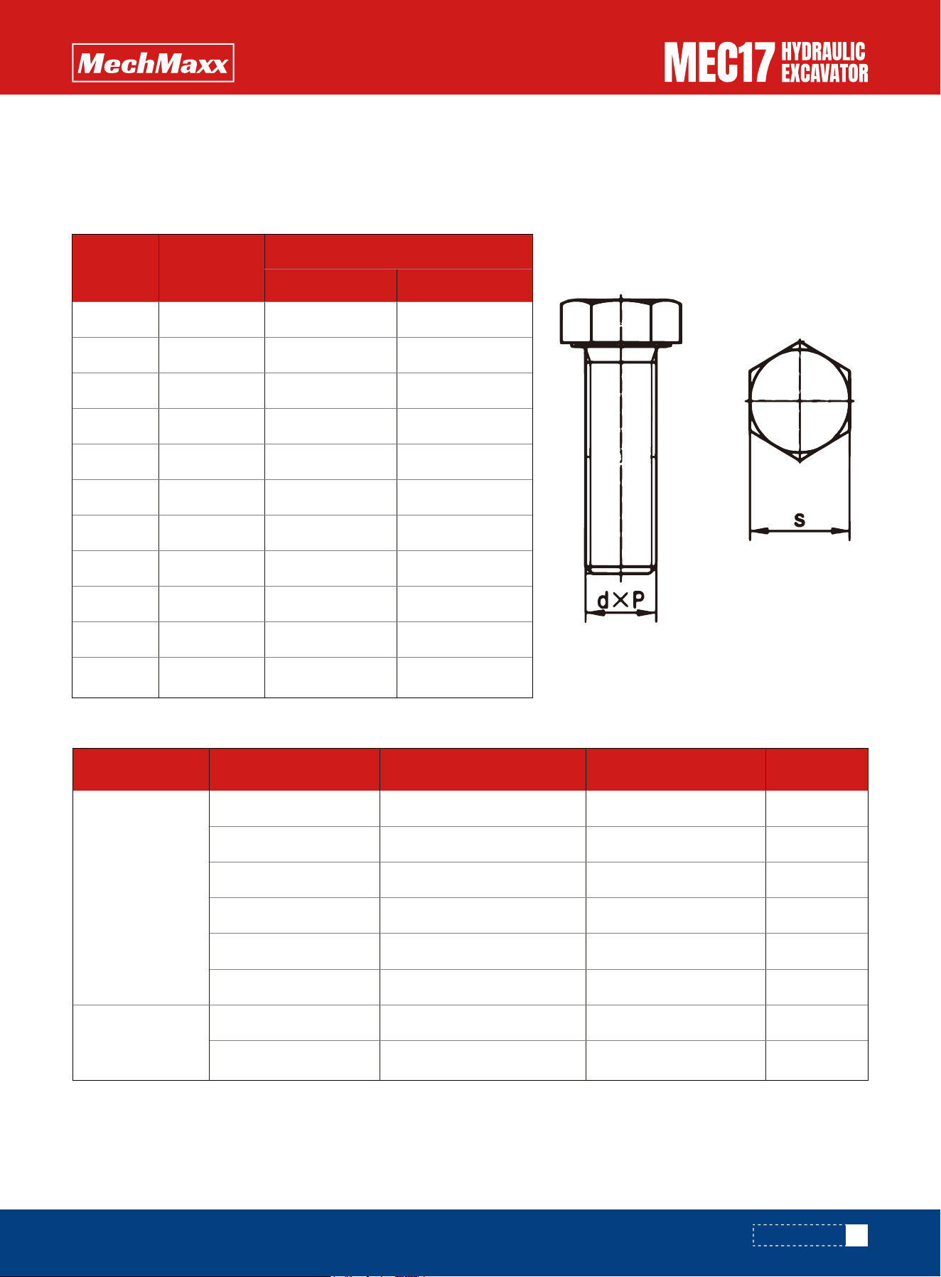
Notice:
L
a
: Light series connector ,S
a
: Heavy series connector,see ISO8434-1 for the distinction of weight series.
Unless otherwise specified, tighten the metric nuts and bolts to the torque shown in the table below.
If it is necessary to replace any nut or bolt, always use a mechmaxx genuine part of the same size as the part that was
replaced.
Tightening Torque List
Apply the following table for Hydraulic Hose:
L
a
S
a
85
www.mechmaxx.com
M6
M8
M10
M12
M14
M16
M18
M20
M22
M24
M27
10
13
16
18
21
24
27
30
34
36
41
11.8~14.7
27~34
59~74
98~123
157~196
245~309
343~427
490~608
662~829
824~1030
1180~1470
13.2
31.4
65.7
112.7
176
279
382
549
745
927
1323
Extent Target
Thread
diameter
Across flats
S/mm
Tightening torque:[N·m (Kgf·m)]
M12X1.5
M14X1.5
M16X1.5
M18X1.5
M22X1.5
M26X1.5
M22X1.2
M24X1.5
14
17
19
22
27
32
27
30
16
16
26
37
47
89
79
84
15-17
15-17
25-28
35-39
45-50
85-94
75-83
80-88
Nominal number Thread Diameter M Width across Flats S Target value Extent
MAINTENANCE

1
2
3
4
5
6
7
8
9
10
11
Fuel hose (fuel tank - fuel pre-filter)
Fuel hose (fuel pre-filter - fuel fine filter)
Fuel hose (fuel fine filter - engine)
Fuel return pipe (engine - fuel tank)
Hydraulic hose (pump drain)
Hydraulic hose (pump return)
Hydraulic hose (boom cylinder - control valve)
Hydraulic hose (arm cylinder - control valve)
Hydraulic hose (bucket cylinder - control valve)
Hydraulic hose (swing motor - control valve)
seat belt
Every 2 years or 3000 hours,
whichever comes first
Every 2 years
1
1
1
1
1
1
4
2
4
2
1
Number Part Name Q'ty Replacement frequency
•To ensure safety, the user must perform regular maintenance on the machine when operating or driving the machine. In
addition, in order to further improve safety, users should also periodically replace parts in the safety critical parts list.
These parts have a particularly close relationship to safety and fire protection, so please contact your mechmaxx for
replacement.
•For these parts, the material changes over time and they are prone to wear or deterioration. However, it is difficult to
completely judge the condition of the parts through regular maintenance. Therefore, the specified time is up, regardless
of the situation, it must be replaced. This is necessary to ensure that these parts always maintain their function
completely.
•If these parts have not returned to the replacement cycle, they must be repaired or replaced immediately.
•If the hose clamp deteriorates, such as deformation or cracks, replace the hose clamp while replacing the hose.
•The following checks should be performed on hydraulic hoses that are not listed as regular replacement parts. If abnor-
malities are found, tighten or replace them.
•When replacing the hose, replace the O-ring, gasket and other similar parts at the same time.
If the machine is equipped with hydraulic hammer, the maintenance schedule of some parts is different. For details, see
"Maintenance Cycle when Using hydraulic hammer" to determine the correct maintenance schedule when performing
maintenance.
Maintenance schedule and procedures refer to the maintenance Table, which is pasted on the vehicle.
Regular Replacement of Safety Critical Parts
Safety critical parts
Maintenance schedule
Maintenance schedule
86
www.mechmaxx.com
MAINTENANCE

For details of the following items, see "Pre-job inspection" in the operations section.
•Cooling system coolant level - check/fill
•Engine oil level - check/fill
•Fuel oil level - check/fill
•Air filter dust indicator - check
•Hydraulic oil level - check/fill
•Electrical wiring - Inspection
•Horn function - check
•Air filter element - inspection/cleaning
•Internal cleaning of cooling system - cleaning/replacement
•Water and sediment in the fuel prefilter - discharge
•Water and sediment in fuel tank - discharge
•Track tension - check/adjust (machine with metal track board, road liner)
•Bucket teeth - replacement
•Engine oil and oil filter element - replacement
•Engine oil and oil filter element - replacement
•Fuel fine filter element - replacement
•Gear oil for walking reducer - replacement
•Air filter main element and safety element - inspection/cleaning
For details on the following items, see the Operation/Maintenance section.
•Working device is filled with grease
•Check coolant level in cooling system, add coolant
•Check engine oil level, add oil
•Check fuel level, add fuel
•Check hydraulic oil level, add oil
•Fuel pre-filter - check/drain
•Check electric wiring
•Check and adjust Alternator belt tension
•Engine oil and oil filter -- check/fill
•Hydraulic oil return filter element - replacement
•Air filter main filter element and safety filter element - replacement
Check before operation
Irregular maintenance
First 50 hours of maintenance (first 50 hours only)
The first 500 hours of maintenance (only in the first 500 hours, and also every 250 hours of maintenance)
The first 1000 hours of maintenance (only in the first 1000 hours, at the same time every 500 hours of
maintenance)
Every 8 hours maintenance
Every 100 hours of maintenance
87
www.mechmaxx.com
MAINTENANCE

•Hydraulic oil return filter element - replacement
•Gear oil for walking reducer - replacement
•The guide cartridge - replacement
•Air filter main filter element and safety filter element - replacement
•Grease for slewing support gear - inspection
•Maintenance should be performed at the same time every 250 and 500 hours
•Grease in oil pool of rotary device - replacement
•Coolant - replacement (recommended)
•Maintenance should be performed at the same time every 250, 500 and 1000 hours
Notice: Special tools are required for inspection and maintenance. Please contact mechmaxx dealer.
•Change hydraulic oil
•Change hydraulic oil
•Maintenance should be performed at the same time every 250, 500 and 1000 hours
•Engine oil and oil filter element - replacement
•Grease for slewing bearings and pinion gear - filling
•Radiator and condenser fins - check/clean
•Gear oil level of walking reducer - check
•Fan belt - check/adjust
•Lock core - maintenance/lubrication
•Hinge - maintenance/lubrication
•Fuel fine filter element - replacement
•The guide cartridge - replacement
•Gear oil for walking gear reducer - replacement
•Fuel pre-filter element - replacement
•Maintenance every 250 hours shall be performed simultaneously
Maintenance per 1000 hours
Every 2000 hours of maintenance
Maintenance every 3,000 hours
Maintenance every 250 hours
Maintenance every 500 hours
88
www.mechmaxx.com
MAINTENANCE
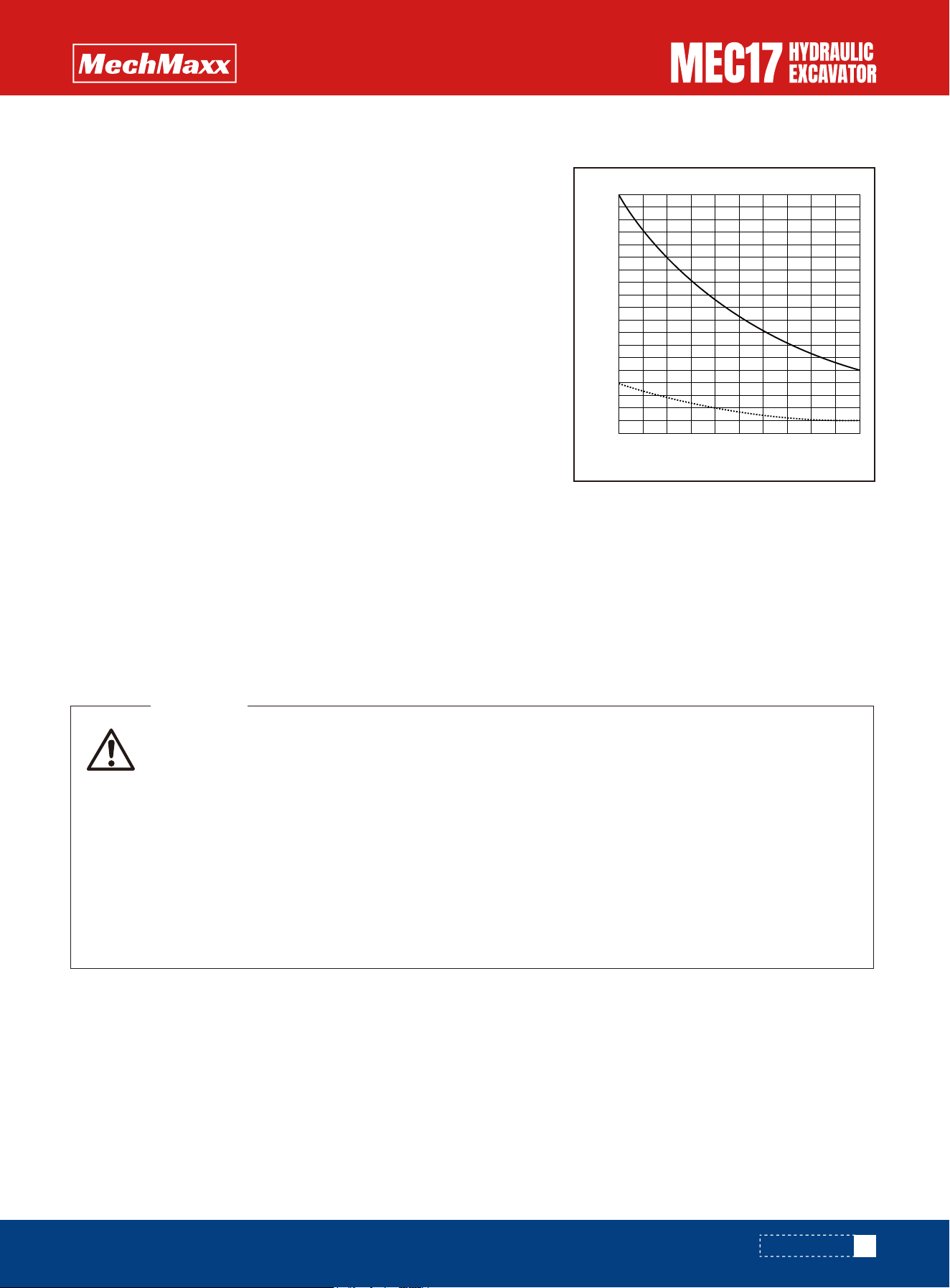
If the engine is operated without sufficient heating, the working device will become slow in
response to the joystick and cannot move as intended by the operator. Therefore, after the engine
is started, idle for 5 minutes to warm up the engine. Especially in cold areas, be sure to carry out
adequate heating operation.
Sudden engine shutdown will greatly shorten the service life of the engine components. So do not
suddenly shut down the engine except in emergencies. The engine should be run at a low idle speed
for about 5 minutes to cool the engine gradually.
After the engine stops, parts and oil are still in a high temperature state, which can easily lead to
burns. We can't start working until the temperature cools down.
Waste oil and liquid should be disposed of in an environmentally friendly manner
WARNING
•Replace hydraulic filter element
•Breaker operating ratio 100% means that only the breaker is used
•Breaker operating ratio 0% means that the breaker is not used
•The hydraulic mailbox breathing valve filter element needs to be cleaned irregularly in the replacement cycle.
•Change oil in hydraulic tank
For machine equipped with a hydraulic breaker, the hydraulic oil deterio-
rates faster than for normal bucket digging operations, so set the mainte-
nance intervals as follows.
When using CI-4, change the oil every 250 hours or 3 months (50 hours for the first time), whichever comes first. The
conditions applicable to the 250-hour interval are:
The oil filter meets the engine specification, as do the original components.
Sulphur content of engine fuel shall not exceed 0.1% by weight.
The oil used meets the requirements
The oil used conforms to "recommended lubricants and accessories".
Select the correct oil viscosity relative to the ambient temperature, see "Correct selection".
Change the oil and oil filter every 100 hours if any of these conditions are not present, or if the machine is operating in an
acidic, particularly dusty environment, or using fuel with sulphur content greater than 0.5%.
On a new machine, replace the element after the first 100 to 150 hours,
then carry out further replacement of the element according to the table
on the right.
Change the oil according to the table on the right.
X: Breaker operating ratio (%)
Y: Replacement interval (H)
(A):Hydraulic oil return filter, hydraulic tank breathing valve filter, pilot
filter filter replacement cycle
(B): Hydraulic oil replacement cycle
Maintenance Interval for Hydraulic Breaker
Maintenance procedures
Engine maintenance and maintenance
Engine oil and oil filter element - replacement
REMARK:
89
www.mechmaxx.com
0 20
500
1000
1500
2000
40 60 80 100
X
Y
B
A
MAINTENANCE
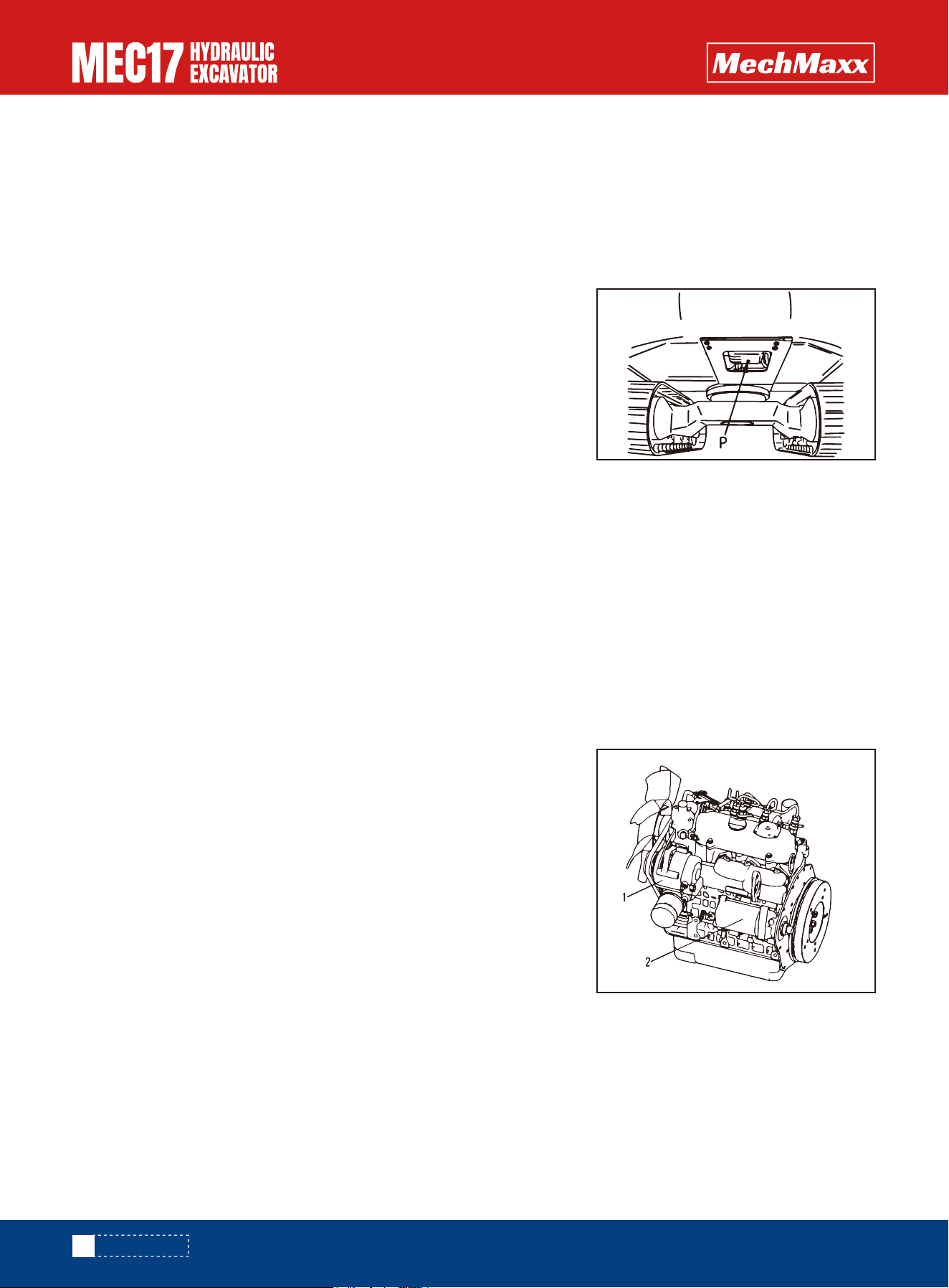
The engine must be stopped while checking the fan belt tension, as rotating parts can cause personal injury.
Check the fan belt every 250 hours.
•Pay attention to
•Pan replacement oil volume: 3.7L
•Prepare a strainer wrench.
•During inspection, if the machine is tilted, it should be in a level state before inspection.
•Need to check the oil level every day, too much or too little oil will cause trouble.
1. Place an oil container directly under the plug (P) at the bottom of the
machine. Loosen the plug with 0.86 in extension sleeve (P).
2. In order not to let the oil splash on the body, do not remove the plug first,
let the oil slowly discharge from the plug (P). At the end of discharge, remove
the plug completely to drain all oil from the sump.
3. Check the oil discharge. If you find a lot of metal shavings and foreign
matter, please contact the dealer.
4. Install plug (P).
Fan belt - check/adjust
NOTE
With about 98N (10kGF) force, press the middle part of the crankshaft pulley and fan pulley, if the deflection is 0.27 ~
0.35 in, it is qualified.
1. Open the rear hood of the engine and lock it with the brace.
2. Loosen the adjusting bolts and mounting bolts of the ALTERNator.
3. Adjust the alternator, press the middle part of the crankshaft pulley and
fan pulley with a force of about 98N, so that the deflection is 0.27~ 0.35 in.
4. Tighten the adjusting bolts and mounting bolts of the ALTERNator.
5. Check whether the pulley is damaged, whether the V-groove is worn and
whether the V-belt is worn. In particular, check whether the v-belt is in
contact with the bottom of the V-groove.
6. If the belt has been stretched without adjustment margin or there is a cut
or crack on the belt, please contact the local dealer for replacement in time.
7. After adjusting the rear cover, put on the rear engine cover and lock it.
CHECK
•lever
•Prepare wooden blocks.
•The surrounding of the hydraulic tank breathing valve needs to be cleaned irregularly during
ADJUST
NOTE
90
www.mechmaxx.com
MAINTENANCE
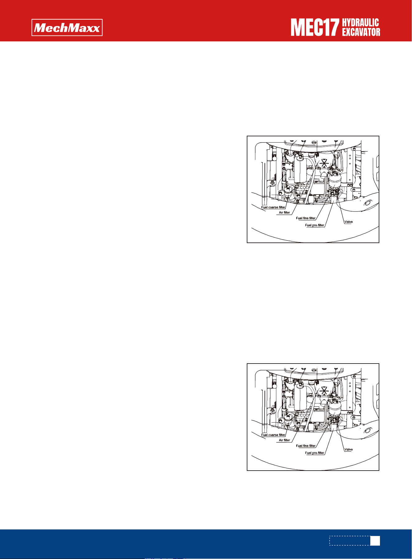
Fuel system maintenance and maintenance
•Only diesel oil should be used when flushing the inside of the tank.
•For routine maintenance, water and sediment in the fuel tank can be discharged from the bottom of the fuel tank plug.
•After engine shutdown, all parts are still in a high temperature state, so
do not replace the filter immediately. The replacement can only be
carried out after the temperature of each part comes down.
•When the engine is running, there is high pressure in the fuel hose. After
the engine is stopped, wait for 30 seconds to release the pressure
before operation.
•Do not go near an open flame.
•Prepare a strainer wrench.
•Prepare a container for discharging fuel.
•1. Open the engine cover, ensure that the brace is locked, and place the
valve in the closed position.
•2. Remove the water collecting cup of fuel pre-filter and drain the water clean. If the water collecting cup contains impu-
rities, clean the water collecting cup with clean diesel oil.
•3. After cleaning the water collecting cup, install the water collecting cup by rotating the filter wrench counterclock-
wise.
•4. Open the valve, loosen the brace and close the engine cover.
•1. Open the rear hood of the engine and lock the rear hood with a brace.
•2. Turn the fuel fine filter element to the left with the filter element
wrench, and remove the filter element.
•3. Clean the filter seat, coat the sealing ring of the new filter element
with oil, turn the filter element to the right by hand, until the sealing
gasket of the filter element contacts the sealing surface of the mount-
ing seat.
•4. Tighten the filter 3/4 to the right with the filter wrench.
•5. After the replacement of the fine filter element, open the valve for
exhaust. See "Fuel system exhaust" for exhaust method.
Fuel pre-filter element - replacement/maintenance
(1) Fuel pre-filter - drainage and cleaning
(2) Fuel oil fine filter element - replacement
Water and sediment in fuel tank - discharge
NOTE
•The water in the water cup needs to be drained frequently, and if it is mixed with the fuel, it will cause damage to the
engine.
•When impurities accumulate in the cup, clean the cup immediately, otherwise impurities may enter the engine and
cause engine clogging or early wear.
NOTE
91
www.mechmaxx.com
MAINTENANCE
• When working with fuel injection equipment, ensure that high-pressure fuel does not come into
contact with unprotected parts of your body.
• If the tank runs out of oil or air enters the fuel system for some reason, air must be expelled from
the fuel system.
WARNING
• Compressed air, steam or water may cause personal injury. Wear protective equipment such as
protective eye mask. Radiator fins are easy to fall down.
• When using compressed air, keep a proper distance from the radiator fins to prevent damage.
• Blow on the radiator core vertically. If the radiator is damaged, it will cause leakage or overheat-
ing.
• Daily inspections are carried out on dusty work sites without limitation of maintenance intervals.
WARNING
Fuel system - exhaust
Maintenance of cooling system
1.Open the rear hood, lock it with a brace, and then open the left door;
2. Use compressed air to remove all sludge, dust and leaves attached to the fins of the water radiator and hydraulic oil
radiator, and clean the air filter at the same time.
3. Close the left door and rear hood and lock it.
•It is not allowed to fill the fuel directly into the filter element of the fine filter, otherwise the fuel that does not pass the
fine filter will cause nozzle blockage or system failure.
• The filter element must use pure parts of mountain reconstruction machine, otherwise it will lead to foreign body entry
or oil injection system failure.
In any case, ensure that the fuel system is completely sealed before starting the engine, otherwise the fuel injection
pump can be seriously damaged as a result.
1. Switch the start key to the ON position to power up the electronic fuel pump and start working.
2. Keep the power on for at least 10 minutes to ensure that the oil circuit is full of fuel oil.
3. Start engine and run engine at low idle for approximately 10 minutes with safety locking lever in lock position.
4. Check to confirm no leakage after startup.
Pay attention to
Radiator and condenser fins - clean
•The exhaust method is the same when the fuel is exhausted.
NOTE
•All fins must be cleaned every 250 hours.
•The air filter on the side door should be cleaned as long as there is debris or too much dust.
NOTE
92
www.mechmaxx.com
MAINTENANCE
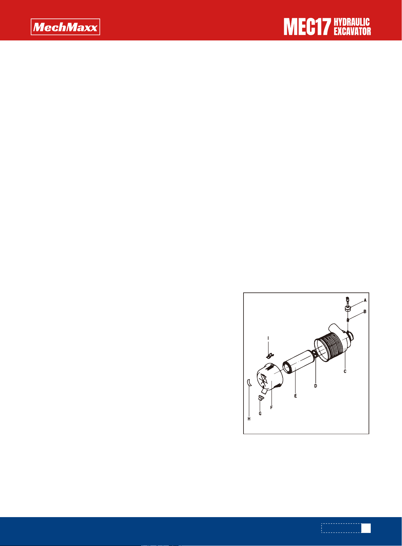
Internal cooling system - cleaning/replacement
Air filter maintenance and maintenance
The air filter prevents dust and other impurities from entering the engine.
The air first passes through the main filter element of the outer filter, and
then through the safety filter element. Engine wear depends largely on the
cleanliness of the intake air. Therefore, it is very important to check the
air filter regularly and maintain it.
Air filter adopts radial seal and double filter form. Air filter structure is as
follows:
A. Differential pressure indicator (optional)
B. joint
C. Air filter housing
D. Safety filter element
E. the primary filter
F. Air filter end cover
G. dust exhausting valve
H. Check The Times label
I. lock
Overview of air filters
•The coolant is antifreeze and antirust. Check the antifreeze performance of the coolant every 500 hours.
•It is recommended to replace the coolant every 2 years or 3000 hours, in advance according to the use of coolant.
•If the coolant is not replaced in time, the cooling system may be blocked and the engine may be stuck to the cylinder.
•The cooling system needs to be cleaned each time the coolant is changed.
•Do not inject cold coolant into an engine that is running or has just finished but the body temperature is still very high.
This may cause cracks in the cylinder block and head.
•Cooling system capacity is approximately 5.05 litres when filling.
•When the plant starts, the cooling system has been filled with a mixture of coolant, water and concentrated antifreeze,
which can lower the freezing point of the coolant and increase its boiling point.
•The concentrated coolant contains an effective anti-rust additive to protect the engine and radiator internal waterways,
but the additive is of limited duration.
•Do not mix the special coolant for mountain reconstructors with any antifreeze or additives made by other manufactur-
ers. The mixture may have negative effects.
•The content of antifreeze should not be less than 40% in the coolant. The proportion of antifreeze to 40% of the coolant
can reduce the freezing point to -13°F. Antifreeze is 50% of the coolant, which can lower the freezing point to -34.6°F.
•When determining the coolant (antifreeze) to water mixing ratio, check the past minimum temperature. In practice,
when determining the mixing ratio, set it at a temperature 50°F below the minimum temperature The replacement
cycle.
NOTE
93
www.mechmaxx.com
MAINTENANCE
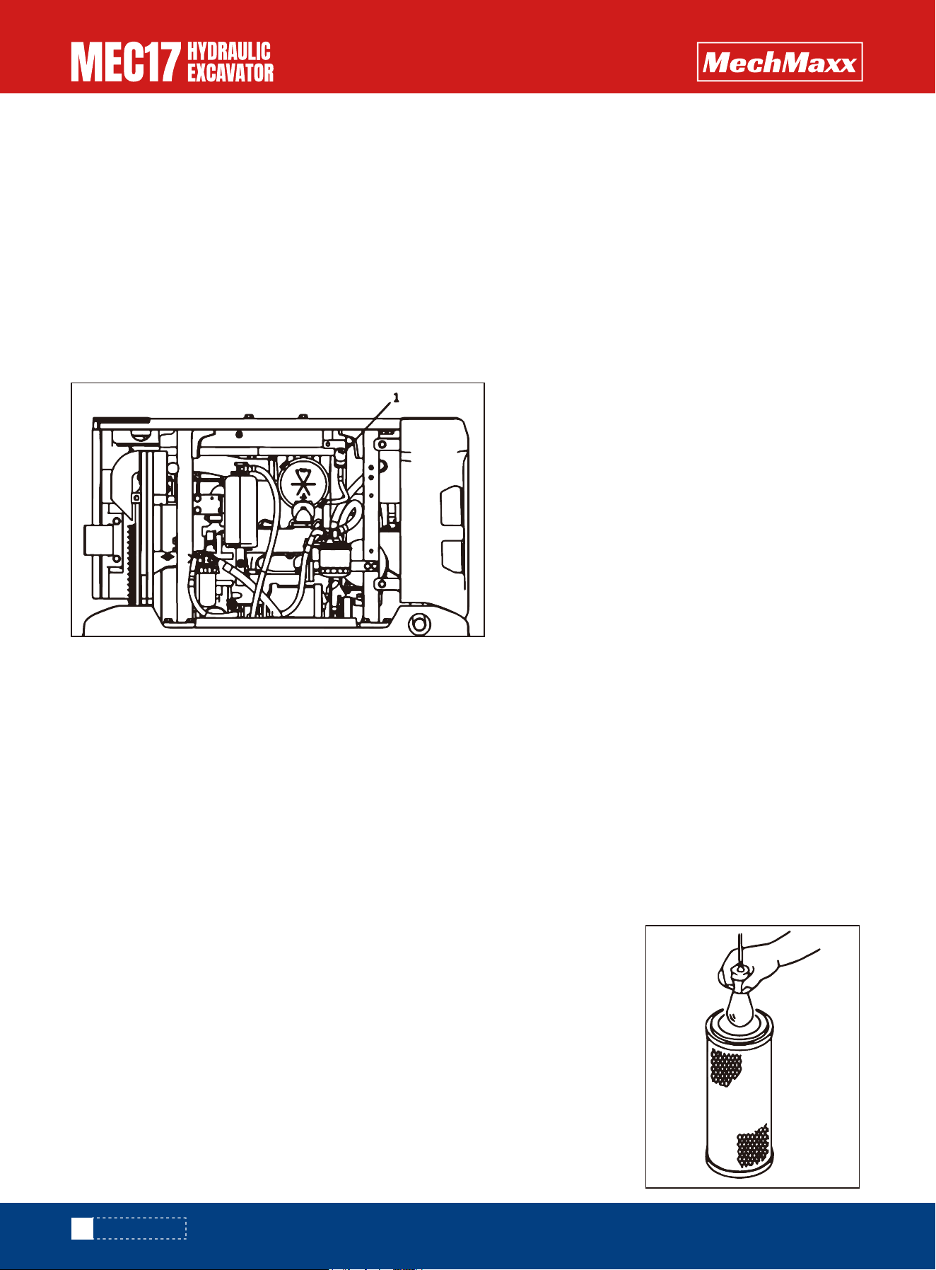
•If the air filter element is frequently cleaned before the alarm, the performance of the air filter can not be fully played,
making its filtering effect worse.
•L In addition, dirt attached to the filter element during cleaning will frequently fall to the inner filter side, suction engine,
resulting in engine wear
•If the dust valve (G) is cracked, damaged or lost, the dust valve needs to be replaced.
If the dust valve is intact, the dust valve needs to be cleaned.
•Main filter element (E) adopts radial seal, there will be a certain resistance when
taking off, should be pulled out while rotating the main filter element, remember not
to beat the shell and the main filter element.
•Do not remove the safety filter element (D), otherwise, dirt is easy to enter and
cause engine failure. Unless the safety filter element is damaged and spare parts are
ready for replacement.
1. Open the engine cover and ensure that the brace is locked.
2. Open the three locks on the end cover of the air filter (I).
3. Remove the end cover of the air filter (F).
4. Empty and clean the end cover and dust exhaust valve (G), and clean the inside of the end cover shell with a clean
cloth.
5. Remove the main filter element (E).
•Under no circumstances should you run an engine without an air filter or if the air filter is damaged.
•Check the pipeline from the air filter to the engine intake manifold periodically for leaks and damage.
•Prepare a spare air filter and store it in a dry and dust-proof place.
•If the engine is inspected, cleaned or replaced while it is running, dust will enter the engine and cause engine damage.
Before performing these operations, shut off the engine.
•There is a danger of dirt flying out and causing injury when compressed air is used. Wear protective glasses, dust mask
or other protective devices.
Open the engine rear hood to check whether the air filter alarm displays alarm
NOTICE
Air filter. - Check
IMPORTANT
Air cleaner - Clean up
NOTICE
94
www.mechmaxx.com
MAINTENANCE
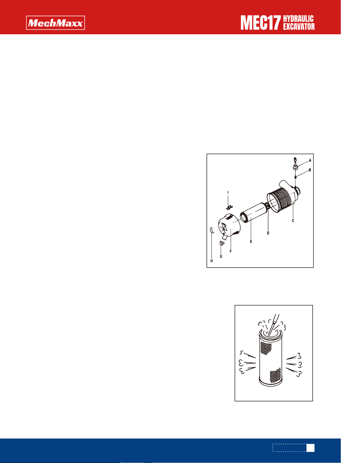
•Must not be knocked to clean the main filter element;
•The life of the filter element can not be judged only by eye observation,
the pressure differential indicator is the most reliable;
•Air filter end cover (F) can not be opened for too long, if there is no
suitable filter element to replace immediately, should immediately cover
the end cover;
• Pure air filter element for mountain reconstruction machine must be
used.
•Mechanical cleaning: the main filter element on a soft, clean object surface carefully beat the end of the filter element,
do not rely on a hard object violently hit or hit the filter element.
•Compressed air cleaning: dry compressed air (less than 0.69mpa {7kg/cm
2
}) from the inside of the filter along the fold
to blow outward, and then from the outside of the filter along the fold to blow inward, and again from the inside to blow
outward, nozzle and filter surface distance is not less than 0.1 ~ 0.2 in.
•The outer filter element needs to be replaced after 6 times of cleaning or after 1000h. The safety filter element should
be replaced when the external filter element is replaced.
•Even if the cleaning times of the outer filter element did not reach 6 times, the alarm still alarms when the filter
element is blocked after cleaning, and the inner filter element and the safety filter element need to be replaced.
8. Push the edge of the main filter element (E) by hand, carefully install the main filter element, and confirm that the main
filter element is fully loaded into the shell.
9. Make the TOP arrow of the end cover (F) face up and install it on the shell of the air filter, and fix it with the lock (I).
•Can not use the force of the end cover to push the main filter element, which will
damage the housing and the lock.
•If the end cover cannot be installed in place because of the main filter element,
remove the end cover and continue to push the main filter element until the main
filter element is installed in place.
•The dust valve on the end cover should be kept facing down for dust removal.
•For each cleaning of the main filter, one label on the check times label (H) at the end
cover of the empty filter should be torn off. The label can be cleaned up to 6 times,
and then it must be replaced.
6. Check and clean the main filter element (E) and shell (C).
7. After cleaning the filter element, use light to illuminate the inside of the filter element or reverse sunlight to check. If
there are holes or thin parts on the filter element, replace them.
Pay attention to
NOTICE
95
www.mechmaxx.com
MAINTENANCE

1. Open the engine cover and ensure that the brace is locked.
2. Open the lock on the end cover of the air filter (I).
3. Remove the end cover of the air filter (F).
4. Empty and clean the end cover and dust exhaust valve (G), and clean
the inside of the end cover shell (F) with a clean cloth.
5. Remove the main filter element (E).
6. Clean the inside of the air filter shell (C) with a clean cloth.
7. Prepare the new main filter element and safety filter element, and check whether the new filter element is damaged,
if there is damage, replace it immediately.
8. Remove the safety filter element (D) and quickly install the new safety filter element.
9. Push the edge of the main filter element (E) by hand, carefully install the main filter element, and confirm that the main
filter element is fully loaded into the shell.
10. Make the TOP arrow of the end cover (F) face up and install it on the shell of the air filter, and fix it with the lock (I).
Safety filter filter efficiency is generally much lower than the main filter, the filter area is much smaller, maintenance
work, can prevent impurities into the engine.
When the main filter is damaged, the safety filter will protect the engine.
If the main filter element has been cleaned or replaced, but the differential pressure indicator alarm, it indicates that the
safety filter element is blocked.
Air filter element - replacement
•Do not remove the safety filter element at this time
•If the dust valve (G) is cracked, damaged or lost, the dust valve needs to be replaced. If the dust valve is intact, the dust
valve needs to be cleaned.
•Main filter element (E) adopts radial seal, there will be a certain resistance when taking off, should be pulled out while
rotating the main filter element, remember not to beat the shell and the main filter element.
Pay attention to
NOTE
Safety filter element can only be replaced, not cleaned.
Safety filter element is generally replaced at the same time when the main filter element is replaced.
Do not remove the safety filter element unless it needs to be replaced.
Remove the safety filter element should be very careful, and the removal action should be accurate in place, so that impu-
rities are not easy to enter the engine.
After replacing the safety filter element, carefully check to ensure that the new safety filter element is installed correctly.
NOTICE
96
www.mechmaxx.com
MAINTENANCE
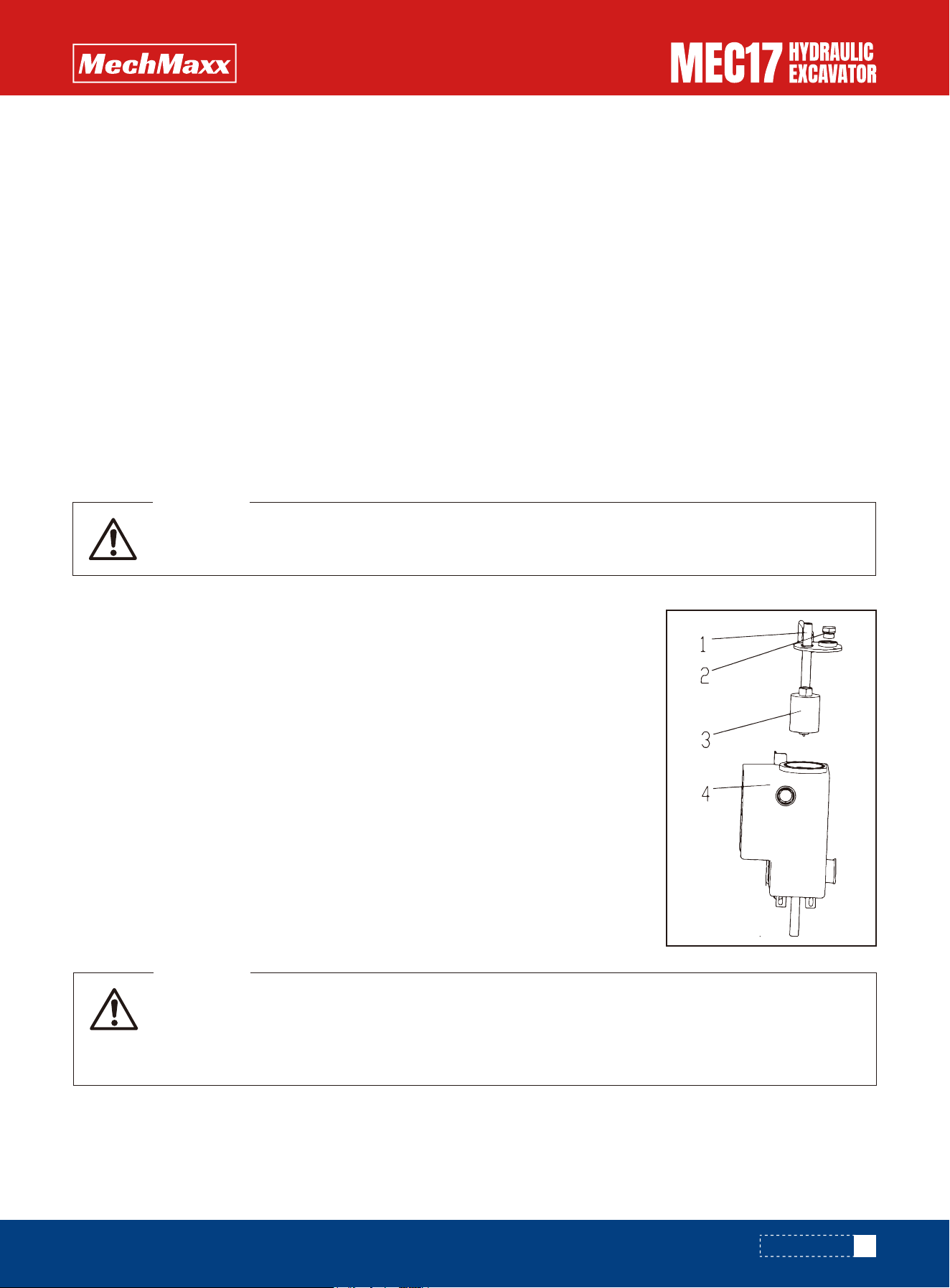
• After the engine is stopped, the parts are still in the high temperature state, so do not immediately
replace the oil filter element. The parts cannot be replaced until the temperature drops.
WARNING
• After the engine is stopped, all parts are still in the high temperature state, so do not immediately
clean the oil absorption filter. The parts cannot be replaced until the temperature drops.
• Oil may spout when the cap of the suction port is removed. Press the top button of the breather
valve to release pressure inside the tank before removing the cap.
WARNING
Operation instructions for electric welding
Maintenance of Hydraulic System
•The battery switch must be turned off before welding the machine or any device installed on the machine.
•Disconnect the battery cable and unplug the cable plug from the electronic controls before any welding is performed on
the machine.
•Turn off the battery switch when disconnecting and reconnecting.
•The grounding wire of welding equipment should be as close to the welding point as possible.
•L Remove all paint within a radius of at least 10 cm (4 inches) around the weld before welding. Because heated paint
gives off harmful gases.
•All paints break down when heated and form large amounts of compounds that can cause pain, irritation and health
hazards if exposed to them for long periods of time.
•L In addition to health hazards, welding quality and strength will be damaged, and even lead to future weld fracture.
Therefore, do not directly on the paint surface welding.
•If the machine is equipped with a hydraulic crushing hammer, the hydraulic oil will
deteriorate faster than normal bucket work. See the item "maintenance cycle when
using hydraulic crushing hammer" for the replacement cycle.
•The filter element of the return oil filter should be replaced every 1000 hours after
the first use and every 1,000 hours after that.
1.Remove the upper flange (1) connecting pipe.
2.Remove the upper flange (1)mounting bolt (plece 2 is the filling port plug cap)
3.Take out the upper flange (1) and return filter(3).
4.Unscrew the old oil return filter element (3),and then replace the new oil return
filter element (3).
5.except the filter element (3)clean the removed parts with clean oil.
6.Restore the pipe connected to the flange.
Hydraulic Oil Return Oil Filter Element - Replacement
Hydraulic tank oil filter element - check/clean/replace
Notice
97
www.mechmaxx.com
MAINTENANCE
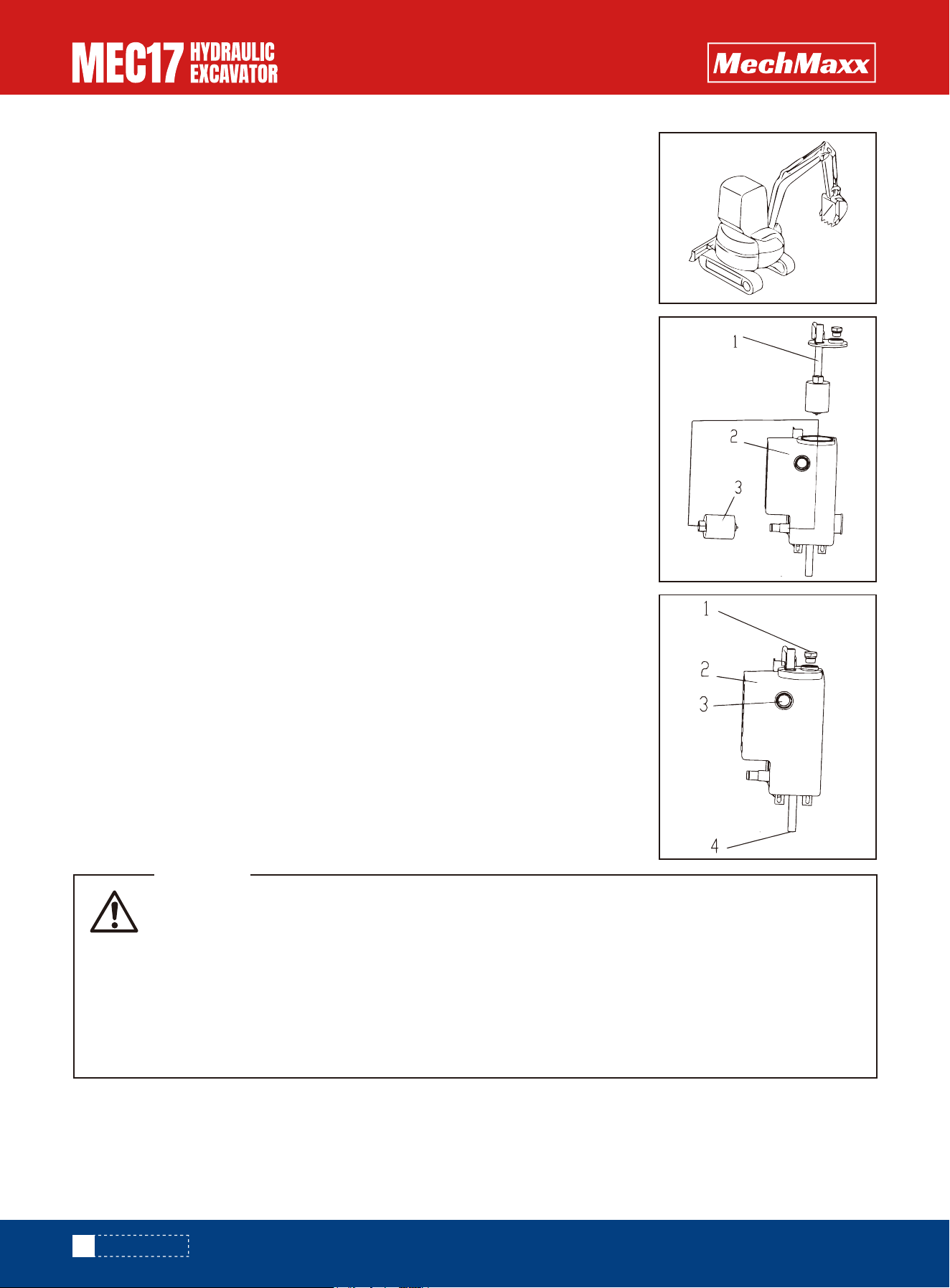
• After the engine is stopped, all parts and hydraulic oil are still at high temperature, so do not imme-
diately replace the hydraulic oil and filter element, or it will cause burns. To wait for the parts and
hydraulic oil temperature down after the start of maintenance.。
• Oil may spout when the cap of the suction port is removed. Press the top button of the breather
valve to release pressure inside the tank before removing the cap.
• Oil receptacles shall have a capacity of at least 110L.
• Fuel capacity: about 110L.
• Prepare sleeve with extension rod, 13mm square or 24mm.。
WARNING
Check and clean the oil filter element of the hydraulic oil tank after the first use of 50
hours and 500 hours, and then check and clean it every 500 hours. Replace every
2000 hours. This maintenance time is halved when using the crushing hammer.。
1.connect the upper method component(1) and remove the connecting bolt.
2.Remove the upper method component (1)
3.Unscrew the oil absorption filter element from the tank(2)
4.Check whether there are metal particles and other impurities on the oil absorption
filter element. If there are, please immediately contact mechmaxx dealer for diagnosis
and maintenance. If not, clean the removed filter element and other parts with clean
diesel oil
5.Clean the oil absorption filter element or the new oill absorption filter element into
the oil tank (2) inner filter seat
Install upper flange(1)seat
6.Install upper flange (1) components and pipes.
Hydraulic Oil Replace
Notice
98
www.mechmaxx.com
MAINTENANCE
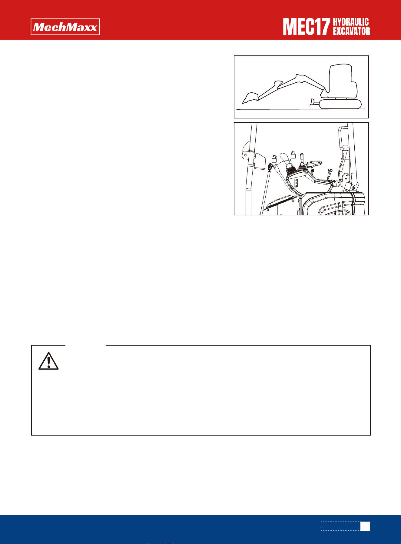
• When the engine stops, the parts and gear oil are still in a high temperature state, which is easy to
cause burns. Wait for the temperature to cool before starting the operation.。
• If pressure remains in the gearbox, oil or studs may fly out. Slowly loosen the plug to release inter-
nal pressure.
• Prepare socket wrench.
• Replace the gear oil in the walking reducer after 500 hours of first use, and replace the gear oil in
the walking reducer after 250 hours of first use. During normal operation, check and add gear oil
every 250 hours, and replace gear oil in the walking reducer every 1000 hours.
WARNING
1.Rotary machine makes the oil discharge screw plug under the
hydraulic oil tank located in the middle of the left and right tracks.
2.Retrieve the oil cylinder of the bucket rod and bucket, lower the
moving arm and dig the bucket tooth into the ground. And lower the
bulldozer to the ground.
3.After flame out, turn the electric lock to the ON position and put the
safety lock lever in the position. Shake the control handle left and right
to release the pressure inside the system. After completion, turn the
electric lock to the OFF position and put the safety lock lever in the
locked position.
4.Place the oil receiving container under the drain screw plug(4)under
the oil tank.remove the lower drain screw(4)to drain oil .and loosen the
upper fill screw plug(1).
5.Remove the upper flange cover after bucket。charging the oil .clean
the top flange cover and the bottom of the tank remaining impurities
and other contaminants
6.Install the upper production cap and drain screw plug (4)and screw it
.check the D shape diagram installed on the cap and screw plug.if
damaged,please replace the 0 shape diagram.
7.At this time ,it is necessary to carry out maintenance at the same time to clean or replace the oil absorption filter
element and oil return filter element.the replacement method is described in the previous three pages
8.After the replacement ,add hydraulic oil to the specified amount of replacement oil through the filling screw plug to
check whether the oil level is in the middle of the middle of oil level gauge .
9.Install the filling screw plug(1) and tighten it.
10.After the replacement of hydraulic oil,put each connecting rod in the middle position make the engine idle for
2-3minutes,exhaust each action,replenish the hydraulic oil to the middle position of the oil level meter and then start the
operation.
Gear Oil in Running Motors and Reducers - Inspection/Refueling
99
www.mechmaxx.com
MAINTENANCE
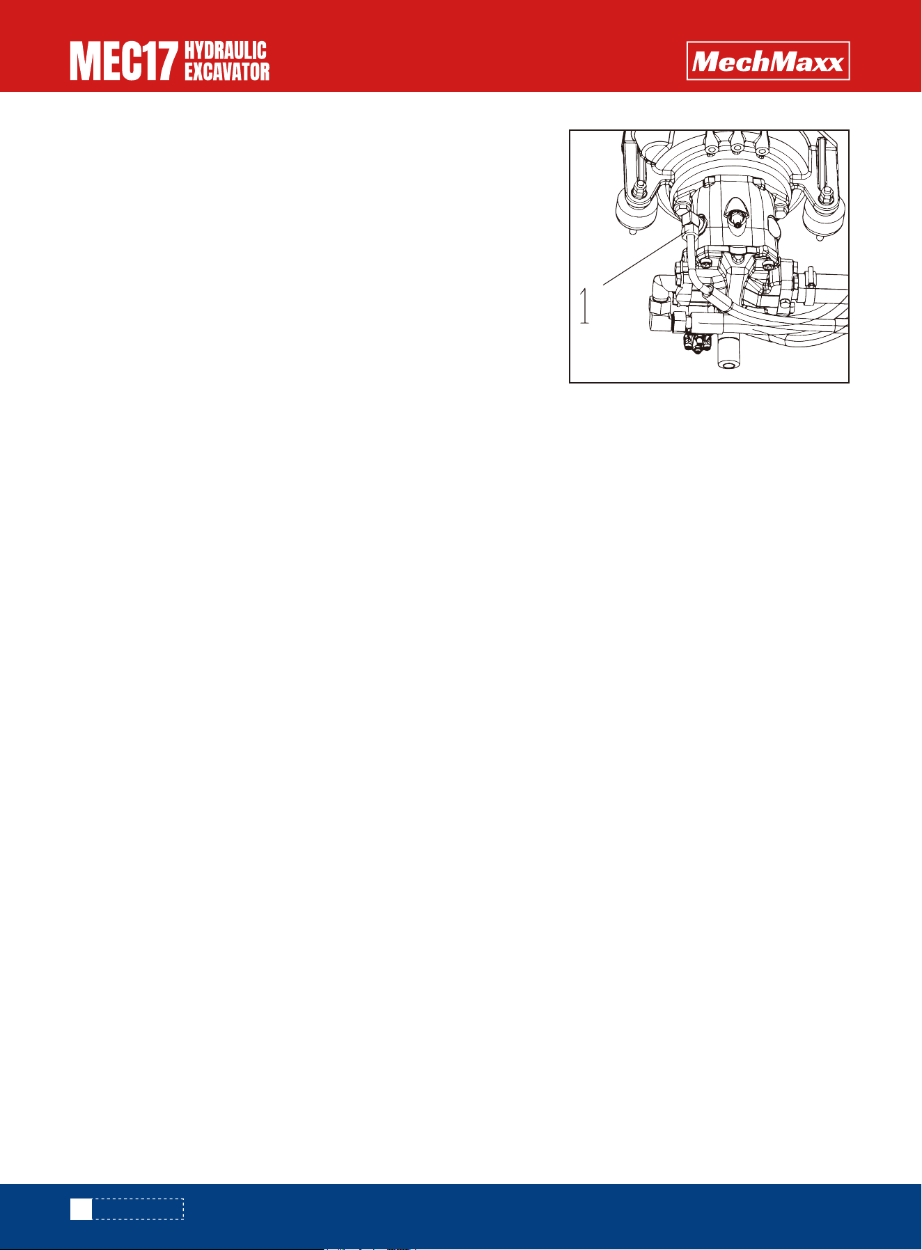
1.Position the motor in the shown position
2.Use an inner hexagon wrench to remove the stud plug of the oil opening
and check whether the internal gear oil is under the gear oil opening and
check whether the internal gear oil surface of the oil opening through the
stud plug hole
3.If the oil level is too low,it is necessary to fill the same specification of
gear oil from the oil filling port.
4.when filling the gear oil flows out of the oil filling hole ,tighten the screw
plug and clean the oil pollution at the reducer shell with a clean cloth
If the pump housing is not filled with hydraulic oil when the pump operation, will cause abnormal high temperature pump,
pump may be prematurely damaged. Therefore, exhaust must be carried out.
1.Discharge air from the main pump
1)Open the rear cover and remove the hose and connector at (1) of the main pump.
2)Slowly fill the oil port with clean hydraulic oil. When it is seen that the liquid level of the oil port is almost full and there
are large bubbles, the filling is suspended.
3)After the liquid level at the oil port stops bubbling, the liquid level will decline. At this time, slow refueling is conducted
again until the liquid level is almost full and stable and no longer drops.
4)Check whether the seal ring of the joint hose is damaged, and replace the seal ring if it is damaged. Tighten the adapter
hose. Clean up any spilled oil.
2.Refer to "starting engine" in the operation section, starting engine. Start the engine at a low idle speed for 10 minutes
before proceeding to the next operation.
3.Drain the air in the oil cylinder
Notice
If the engine is initially run at high speed and the cylinder is operated to the end of the stroke, damage to the plunger
seal will result from air entering the cylinder.
1)Run the engine at low idle speed, and extend and withdraw each cylinder for 4 to 5 times. Be careful not to operate the
cylinder to the end of the stroke (stop at 4 in from the end of the stroke).
2)Then, operate each cylinder to the end of its stroke for 3-4 times.
3)Finally, operate each cylinder to the end of its stroke 4-5 times to completely exhaust air.
4)Exhaust air from accessories (when equipped with accessories)
If a crusher or other accessory is installed, run the engine at a low idle speed and repeatedly operate the accessory pedal
(about 10 times) until air is expelled from the accessory oil path.
Notice
•If the manufacturer has specified the method of exhaust from the annex, exhaust in accordance with the specified
method.
•After the exhaust operation is completed, shut down the engine and wait 5 minutes before starting again to eliminate
the oil bubbles in the hydraulic cylinder.
•Check for leaks and wipe up any spilled oil.
Notice
Hydraulic System - Exhaust
100
www.mechmaxx.com
MAINTENANCE
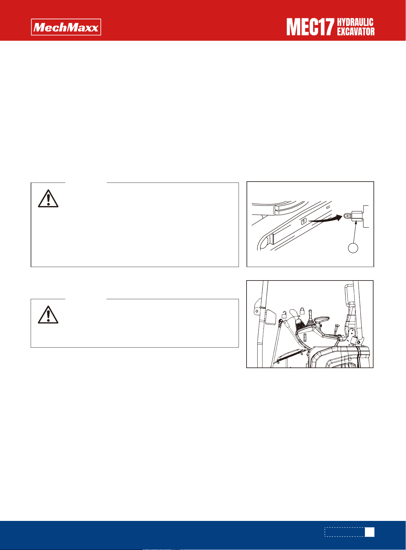
Be sure to loosen the plug.1More than one lap.
If the screw plug1Loosened more than a circle, under
the high pressure of grease, there is a risk of flying out.
At this point, do not loosen the screw removal plug1Do
not face the plug for any part other than the plug1The
installation direction of the.
If the method provided here does not loosen the track
tension, contact the dealer and commission the repair.
WARNING
• It is dangerous if the work equipment is mistakenly
moved when replacing the teeth. Set the work equip-
ment in a stable condition, stop the engine, then set
lock lever securely to the LOCK position.
WARNING
Replace the teeth before the wear reaches the adapter.
5.After the above exhaust is completed, check the oil level of the oil gauge of the hydraulic oil tank. If it is insufficient,
add the hydraulic oil to the specified oil level.
Wear of the pins and bushings of the lower body varies with operating conditions and soil types. Therefore, in order to
maintain the standard tension, to each 250 Check the tension of the track for hours.
For inspection and maintenance, park the machine in a firm, flat place.
1.Run the engine at low idle speed and slowly move the machine forward for a distance equivalent to the length of
contact between the track and the ground, then stop the machine.
2.Check whether the track board is broken or damaged.
CHECK
Track Tension-Adjustment
Replace Bucket Teeth
The grease filling point of the working device lubricates every 8 hours (every day).
If there is abnormal noise in the parts that need lubrication, the lubrication should be carried out regardless of whether
there is time for maintenance.
When excavating in water (on civil land, etc.), lubricate the pin shaft immersed in water.
1.Lubricate according to the lubrication position in the right picture. Lower the actuator to the ground and shut off the
engine.
2.Grease pump is used to inject grease through the grease nozzle shown by the arrow.
3.After lubrication, wipe off the old squeezed grease
(1)Bucket and connecting rod connecting pin (1 place)
(2)Bucket bar and bucket connecting pin (1 place)
(3)Bucket bar and rocker arm connecting pin (1 place)
(4)Both end of bucket cylinder (2 place)
(5)Bulldozing shovel shovel cylinder at both ends (2 place)
Working Device Grease - filling
Notice
Crawler tension-inspect/adjustment Machine with metal treads
101
www.mechmaxx.com
5
MAINTENANCE
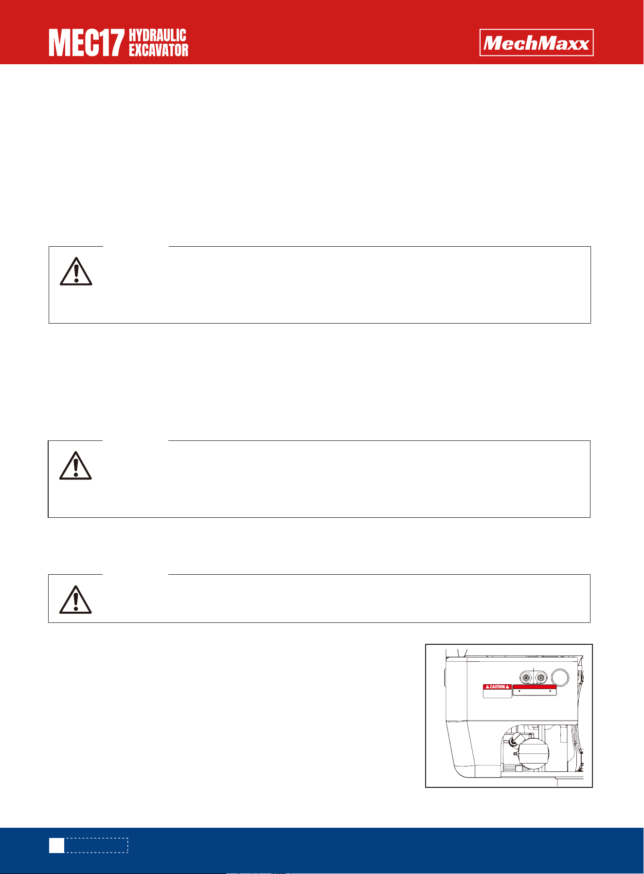
• After the door lock is used for a period of time, there will be dust and impurities in the lock core,
which will cause the lock core to become stuck and fail to open. Do not force it to open, otherwise
the lock core will be damaged.
• Fill the lubricant every 250 hours.
WARNING
• After the hinge is used for a period of time, dust, impurities, etc. may cause the hinge to be stuck
and the door/cover to be closed. Do not forcibly open the door/cover at this time, otherwise the
door/cover will be damaged.
• Add lubricant once every 250 hours.
WARNING
Do not turn the slewing bearings and slewing pinions while lubricating them.
WARNING
(6)Push shovel root pin (2 place)
(7)Both ends of boom cylinder (2 places)
(8)Both ends of cylinder bucket rod (2 place)
(9)Bucket rod cylinder piston rod end (1 place)
(10)Boom root pin (1 place)
(11)The swing frame is connected with the platform shaft(2 place)
(12)Yaw both ends of cylinder (2 place)
When the key is inserted halfway, the lock core dust cover is opened. At this time, the carburetor cleaning agent is
sprayed into the lock cylinder. The key is fully inserted into the lock cylinder for several rotations, half of the key is pulled
out, and the cleaning agent is sprayed again. It can effectively remove internal impurities.
After cleaning, add a small amount of diluted lubricant.
In addition, pre-tighten the hood lock shaft and apply a small amount of lubricant to the lock shaft and lock contact.
Clean dust and impurities from the door/cover and apply a little lubricant to the hinge.
Lubricate the slewing bearing and pinion grease every 250 hours. Do not lubricate
frequently.
1.Lubricate through the yellow nozzle shown by the arrow (right side of the car).
(1) slewing support (1 place)
(2) rotary gear (1 place)
2.After lubrication, wipe off the old squeezed grease.
When lubricating the slewing bearings and slewing gears, the machine may be
rotated slightly to change its position.
Maintenance and Lubrication of Hinge
Filling of Grease
Slewing and Pinion Grease - Check/Refill
Maintenance and Lubrication of Lock Core
102
www.mechmaxx.com
Swing bearing Swing gear
GREASE INJECTION POINT
Fill grease every 250 hours
(Don't fill frequently)
MAINTENANCE

Before using the vibratory compactor, the operator must carefully read the operation manual in detail and strictly follow
its instructions. Inexperienced operators must undergo formal and systematic training before operating the machine. If
the compactor is damaged due to failure to read the manual or lack of proper training, the manufacturer will not be held
responsible.
Operator Instructions
•The eccentric assembly must be serviced regularly; its normal warranty period is 3 months.
•During operation, gear oil must be replaced in time (recommended every 3 months) to prevent damage or wear caused
by foreign particles, which may lead to cylinder and piston damage. The manufacturer assumes no responsibility for such
damages.
•Prolonged improper compaction may cause floor deformation or damage to the damping block; the manufacturer will not
be responsible.
Use dedicated pipelines designed for the vibratory compactor. During disassembly, ensure the pipes and joints remain
clean. If contamination is introduced during disassembly, causing motor scoring or oil leakage, the manufacturer will not
be responsible.
Eccentric Assembly Maintenance and Usage
Pipeline
Before installing the vibratory compactor, the hydraulic oil must be filtered, and the oil tank cleaned. The excavator’s oil
must be replaced regularly according to its service schedule. Damage to the motor caused by untimely oil replacement is
not covered by warranty.
Hydraulic Oil Usage
After the first hour of operation, the operator must carefully check whether all bolts and nuts are loose. Afterwards, check
every 10 hours. Tighten if necessary. Regular inspection of bolts and nuts should be part of routine maintenance. Re-tight-
en as required during assembly.
Bolts and Nuts Usage & Maintenance
•To maximize efficiency, apply appropriate pressure—neither too high nor too low. Stop operation immediately if cracks
or fractures appear to avoid harmful “idle striking.”
•Do not use the compactor to support the excavator for long periods.
•Do not work at the same point for more than 30 seconds.
•Do not operate underwater or drop the compactor intentionally.
Operating Method
•Do not connect the main inlet and return ports incorrectly; damage caused by incorrect connection is not covered by
warranty.
•Do not operate under excessively high pressure; damage or leakage caused by excessive pressure or back pressure is
excluded from warranty.
•It is recommended to connect the return line directly to the oil tank to prevent unstable back pressure that may damage
the motor.
Special Notes
103
www.mechmaxx.com
VIBRATORY COMPACTOR QUALITY WARRANTY CERTIFICATE
VIBRATORY COMPACTOR QUALITY WARRANTY CERTIFICATE

Hydraulic Motor 6 months
6 months
6 months
3 months
3 months
3 months
No warranty
Housing cracks, output shaft breakage: free replacement within 1
month; oil leakage after 3 months not covered; user must purchase
seals. (High-pressure return must go to oil tank, otherwise cracks
are not covered.)
Damage caused by improper operation or unauthorized reinforcement
is not covered; steel plate cracks within 3 months: cracked part
replaced; welding cracks: customer may weld; if unable, manufacturer
provides free welding (other costs not covered).
Damage caused by poor gear oil maintenance or excessive idle
striking not covered.
Damage caused by foreign matter, overdue seal replacement, poor
maintenance, user errors, or external impact is not covered. Sticking
after one month not covered.
Damage caused by poor maintenance, external impact, or
over-adjustment of the relief valve is not covered.
Highly dependent on operator usage; no warranty or maintenance
provided.
Accelerated wear due to lack of lubrication is not covered.
Housing Assembly
Eccentric Assembly
Check Valve
Pipeline Assembly
Damping Block
Bearing
Part Name Warranty Period Warranty Coverage
Warranty Scope
Special Notes for Hydraulic Vibratory Compactor Use
1.The manufacturer is only responsible for quality-related issues of the compactor itself, not for related losses such as
downtime or work injuries.
2.Damage to excavator parts caused by excessive pressure adjustment or vibration is not covered.
3.No personnel may be within a 10-meter radius during operation; any losses resulting from violation will not be covered.
1.Operate vertically with the compaction plate level; ensure even force on all sides. Do not operate at an angle to avoid
cracking the damping block.
2.Damping blocks are consumable parts and not covered by warranty.
3.Recommended operating pressure: 180–200 Kg/cm². Excessive pressure may damage the motor.
4.Damage caused by excessive pressure is not covered.
5.The main return oil line must go directly to the tank. When the motor stops, the eccentric assembly produces a momen-
tary pulse due to inertia. Poor return flow can easily damage the motor. Note: For compactors above 15 tons, do not
connect the pilot return line. If the main return line does not return to the tank (or is overloaded), motor leakage or
cracking is not covered.
6.The working surface must not contain protruding hard objects; damage to the bottom plate caused by localized stress
is not covered.
Screws, nuts, couplings, and joints are not covered by warranty. Loss, breakage, or deformation caused by failure to tight-
en nuts, collisions, or fractures are excluded.
The manufacturer reserves the right of final interpretation.
Disclaimer:
104
www.mechmaxx.com
VIBRATORY COMPACTOR QUALITY WARRANTY CERTIFICATE
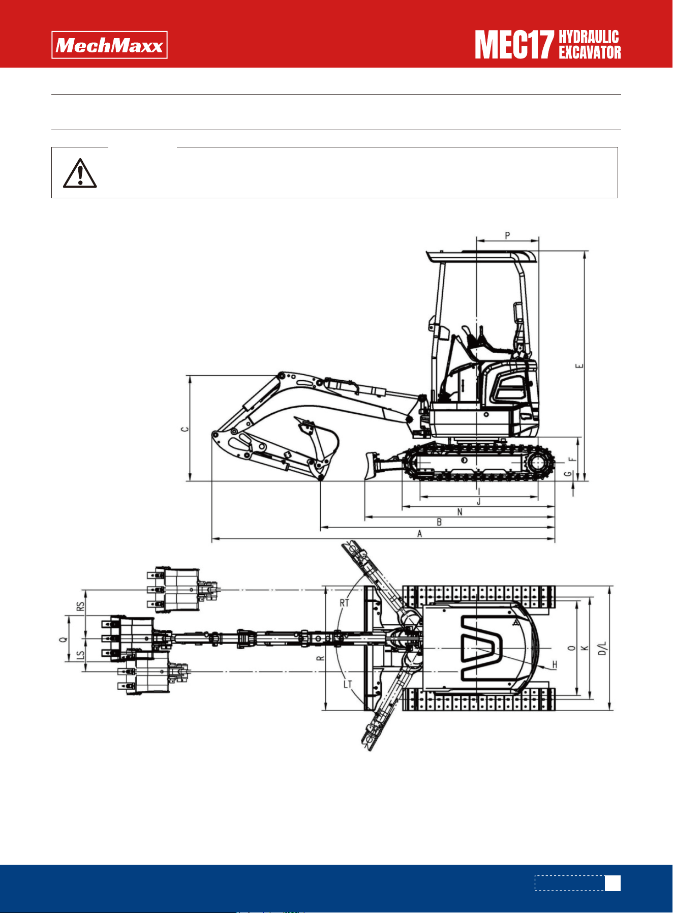
Please read and make sure that you understand the SAFETY section before reading this section.
WARNING
Specifications
105
www.mechmaxx.com
SPECIFICATION
SPECIFICATION

A
B
C
D
E
F
G
H
I
J
K
L
M
O
P
Q
R
RS
LS
RT
LT
Overall length
Grounding length (Transportation)
Overall height(to the top of boom)
Overall width
Overall height(to the top of cab)
Counterweight ground clearance
Min. Ground clearance
Tail radius of turning
Tumbler center distance
Length of track
Gauge
Track width
Track shoe width
Turntable width
Radius of upper structure
Total width of bucket
Bulldozing shovel width
Right arm offset
Left arm offset
Right offset angle of boom
Left offset angle of boom
Ear /Outside noise
Hand-arm system
Whole body vibration
Standard bucket
Travel speed
Engine type
Engine power
Operating mass
Main valve
Hydraulic pump
Swing motor & Reduction gear
Climbing ability
in
in
in
in
in
in
in
in
in
in
in
in
in
in
in
in
in
in
in
°
°
dB
m/s
2
m/s
2
m³
km/h
kW
lbs
L/min
Mpa
r/min
°
140
96
43.5
38.9/51.5
94.6
18.1
5.7
25.5
48.4
62.7
30/42
38.9/51.1
9
78.7
39
19
38.9/51.1
20
13.5
51
61
80/93±2.5
2.5±0.1
0.5±0.1
0.04
2.2/4.3
Kubota-D902
11.8@2300/min
3968
64.4
23
9.5
30
Item (MEC17) Unit Parameter
106
www.mechmaxx.com
SPECIFICATION
Specifications
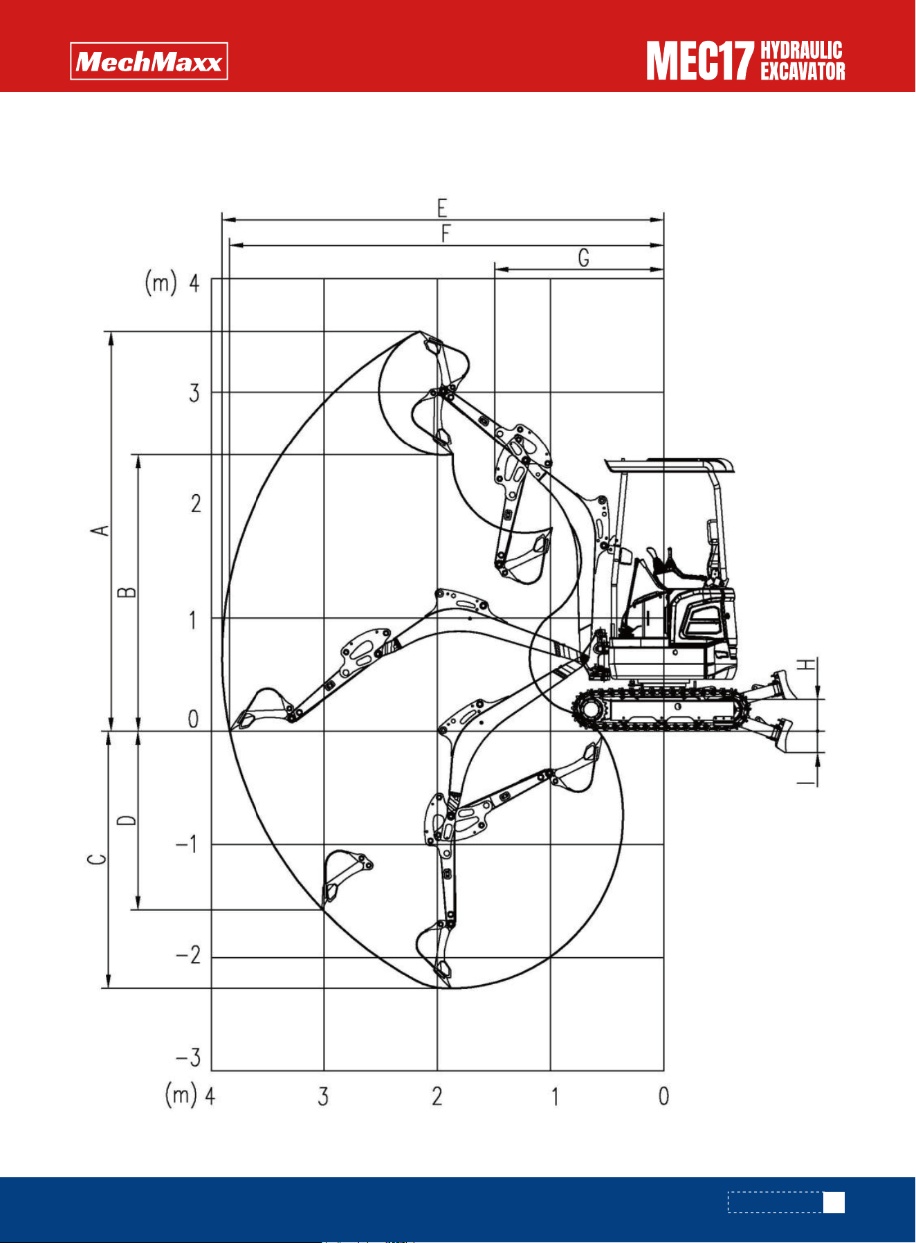
www.mechmaxx.com
SPECIFICATION
Working Ranges
107
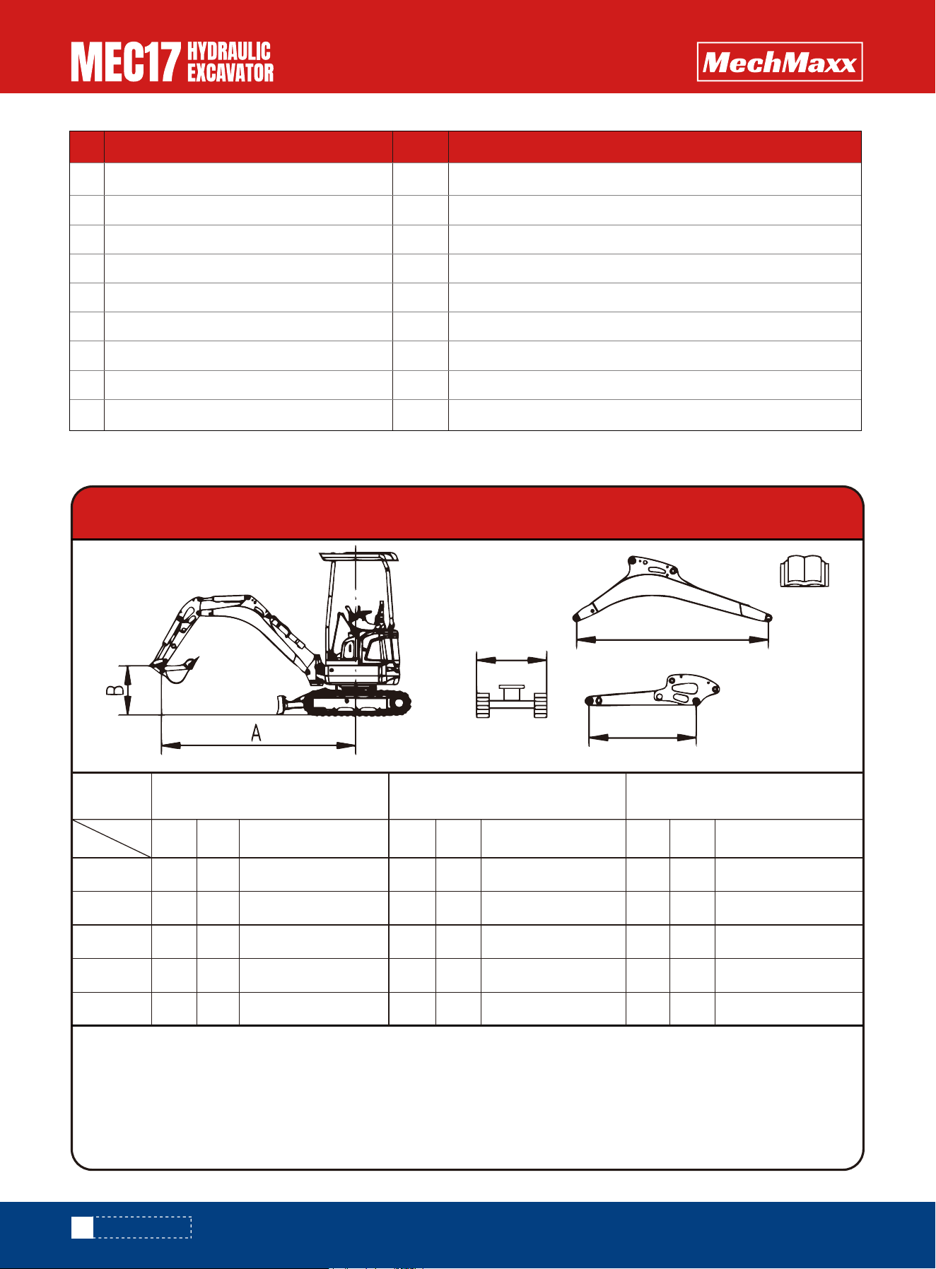
108
www.mechmaxx.com
SPECIFICATION
Lifting Capacity Form
A
B
C
D
E
F
G
H
I
Max. Digging height
Max. Dumping height
Max. Digging depth
Max. Vertical Digging depth
Max. Digging reach
Max. Digging reached at ground level
Min. Swing radius of work equipment
Max lifting height of the blade
Max cutting depth of the blade
in
in
in
in
in
in
in
in
in
139.1
96.2
89.3
75.1
153.9
151.3
58.8
11
7.4
Item Unit Parameter
LIFTING CAPACITY FORM
NOTICE:
1.Please refer to the Operator's Manual for other details.
2.According to IS010567,the rated load is 75% of the effective static tipping load,or 87% (*)of the rated hydraulic
lifting load (the standard value is the smaller one).It's able to turn 360 degrees and work on the flat ground.
3.Lift capacity stays with ±5% for all available track shoes.
Lift
Capacity
A in
B in
78.7
9 8 .4
78.7
554*
641*
438*
422* 338
155
333
300
272
147
137145305
279
323*@ (2577) 323*@ (2577)
312@ (2577)
198@ (2965)
124@ (3316)
109@ (3261)
138@ (2767)
338*@ (2965)
205@ (2965)
131@ (3316)
115@ (3261)
144@ (2767)
366*@ (3316)
356*@ (3261)
304*@ (2767)
404*
39.3
0
-39.3
118
78.7
At Max. Radius @(mm)
At Max. Radius @(mm)
118
78.7
3 7 .4
51.1
71.9
At Max. Radius @(mm)
118
RATED LIFT CAPACITY
OVER BLADE,BLADE DOWN -kg
RATED LIFT CAPACITY
OVER BLADE,BLADE UP-kq
RATED LIFT CAPACITY
OVER SIDE,BLADE UP-kg

The lifting capacity is based on the criteria of the machine being level on
a firm supporting ground. When the machine is operated in conditions that deviate from these criteria (e.g. on soft or
uneven ground, on a slope or when subject to slide loads), these conditions shall be taken into account by the operator
and need contract manufacture for safety operation.
This manual is used as the machine maintenance data, the recorded information including text, data, pictures or other
items may be inconsistent with the actual products sold, this manual cannot be used as the basis of product style, the
purchase of products shall be subject to the actual delivery. Products are subject to change without prior notice.
Standard Configuration and Digging Force
Operating Weight and Ground Specific Pressure
Disclaimer
109
www.mechmaxx.com
Arm Length
Boom Length
Bucket capacity
Arm digging force
Bucket digging force
in
in
m³
kN
kN
37.4
71.9
0.04
9.5
16
Track shoes width
Operating weight
Ground pressure
in
lbs
kPa
9
3968
29
SPECIFICATION
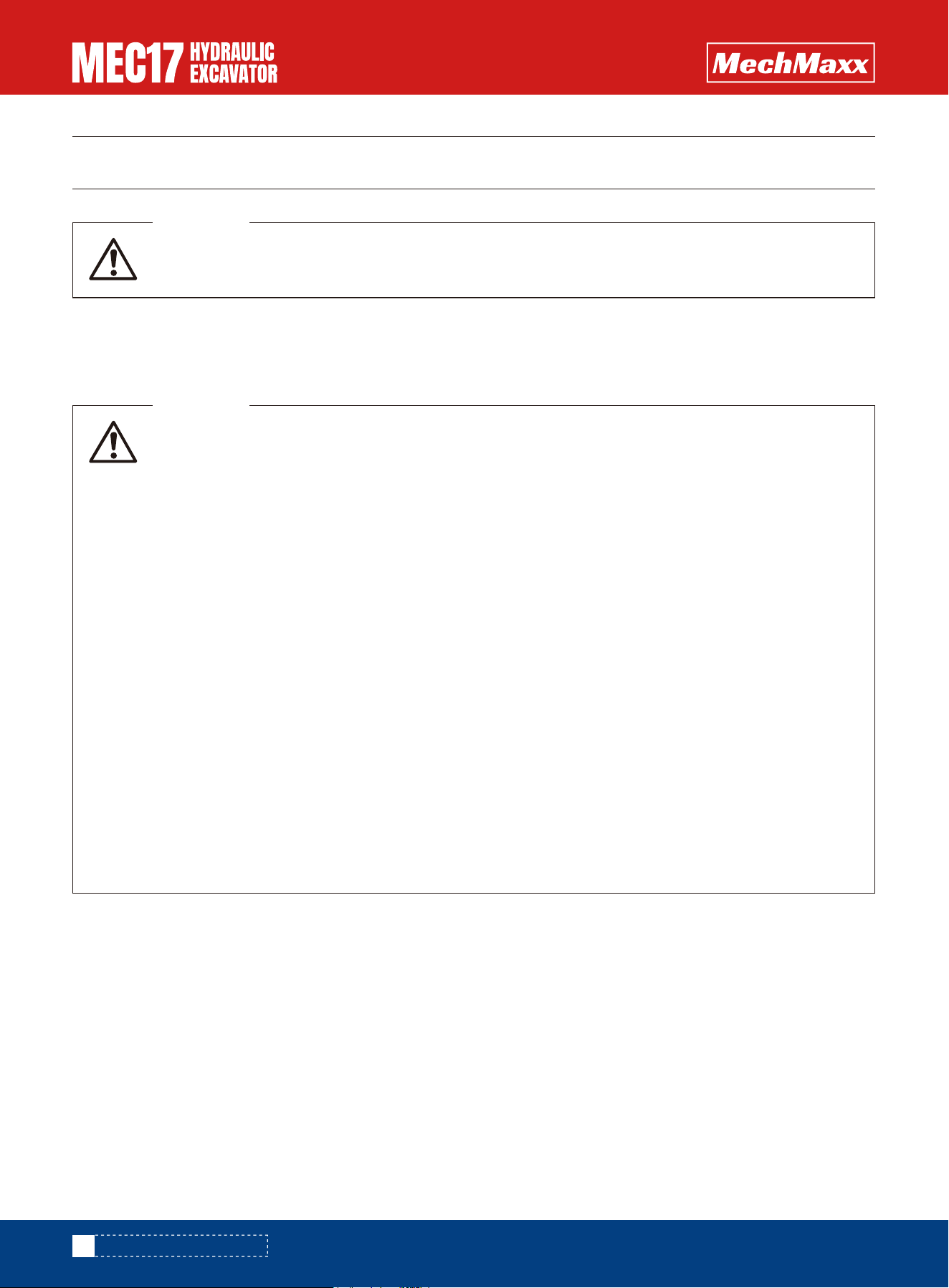
Please read and make sure that you understand the SAFETY section before reading this section.
WARNING
General considerations
• Accessories are powerful tools. To prevent serious injury or damage, use them correctly.
• Read through the attached instructions. Do not use attachments without fully understanding the
instructions.If the instruction manual is lost, contact the manufacturer or attachment sales com-
pany for a new one.
• Install the necessary front cover on the machine as attached.
• Depending on the attachment, vibration noise will make it difficult for colleagues to communicate
instructions. Before starting operation, assign a conductor and determine the signal to be used.
• Do not perform rotary operation with heavy loads on the attachment. Doing so on slopes is particu-
larly dangerous.
• A machine with a crusher hammer has a heavier load on the front part of the work unit and is unsta-
ble compared to the one with a bucket. To avoid the risk of tipping, do not operate when the attach-
ment is turned sideways.
• When accessories are installed, the range and center of rotation of the machine are different. The
machine will move unexpectedly. Be sure to know the machine properly.
• Set up some security lines around the machine before operation to prevent people from entering.
Do not operate the machine when there is a man near it.
• To prevent serious accidents caused by misoperation, do not put your foot on the pedal except
when operating the pedal.
WARNING
When installing attachments or options to the machine, it is necessary to pay attention to safety. Please obey the follow-
ing precautions strictly when selecting, installing, or using attachments or options.
ATTACHMENTS AND OPTIONS
Safety First
When removing or installing the attachment or option, obey the following precautions, and take care to ensure safety
during the operation.
•Carry out the removal and installation operation on a flat, firm ground surface.
•When the operation is carried out by two or more workers, choose the leader and follow his instructions.
•Use a crane when handling heavy objects (more than 25 kg (55 lb)). (The crane must be operated by a qualified opera-
tor.)
•Never go under a load raised by the crane.
•Do not carry out operations with the load kept raised by the crane. Always use a stand to prevent the load from falling.
•When removing a heavy part, consider the balance after it is removed. To prevent the machine from tipping over, set a
support in position if necessary before removing the part.
•Before installing or after removing the attachment or option, set it in a stable condition to prevent it from falling over.
Precautions when removing or installing
110
www.mechmaxx.com
ATTACHMENTS AND OPTIONS
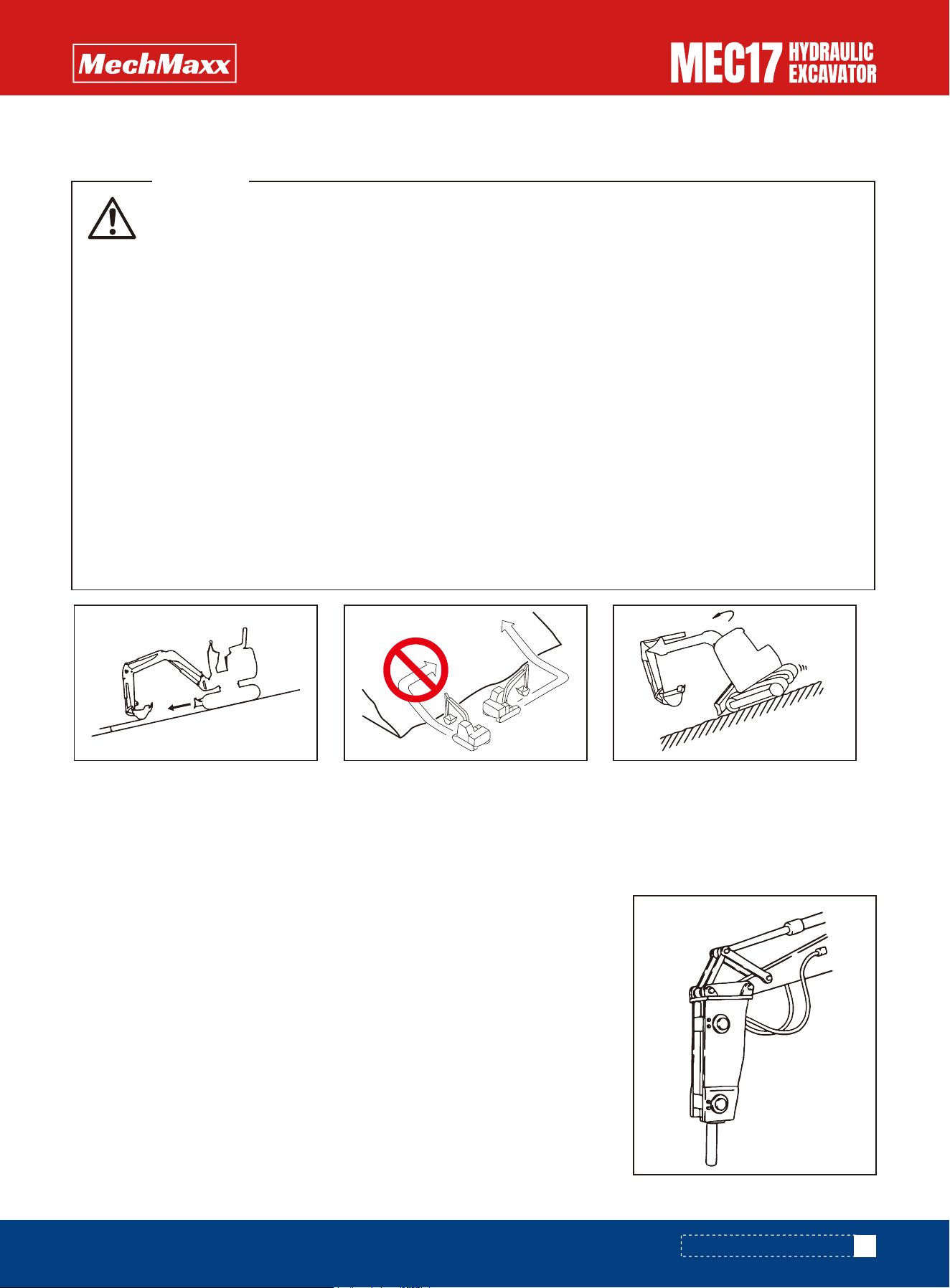
When long or heavy work equipment is installed, remember the following precautions.
• Before starting operations, move the machine to a safe place and carry out a test operation to
make sure that you fully understand the movement, center of gravity, and working range of the
machine.
• Do not swing the work equipment if the machine is at an angle. If the work equipment is swung
with the machine at an angle, there is danger that the machine will tip over.
• Always maintain a safe distance from obstacles in the surrounding area when operating. If long
work equipment is installed, the working range becomes larger.
• The swing overrun (the distance the work equipment moves before completely stopping after the
swing brake is applied) will be greater. There is danger of hitting objects if the swing overrun is
miscalculated, so allow extra space to the swing position when swinging.
• The hydraulic drift of the work equipment (the amount of the work equipment moves down under
its own weight when it is stopped in a raised position) also becomes greater. Do not stop the work
equipment in a raised position; always lower it to the ground.
• Do not swing, lower, or stop the work equipment suddenly. There is danger that the machine may
tip over.
• Do not suddenly extend or retract the boom cylinder. The shock may cause the machine to tip over.
WARNING
Select the optimum model of attachment for a hydraulic excavator on which it is to be mounted. Depending on machine
models of hydraulic excavator, the kind of attachments or the model of specific attachments that can be mounted will
vary.
Notice
•Crushed rock
•Demolition work
•Road construction
This attachment can be used for a wide range of applications including demoli-
tion of buildings, breaking up road surfaces or slag, tunnel work, rock crushing
and breaking operations in quarries.
Main Applications
Recommended Attachment Operations
Hydraulic Breaker
Attachment Installation
111
www.mechmaxx.com
0.7 to 1.1 in
ATTACHMENTS AND OPTIONS
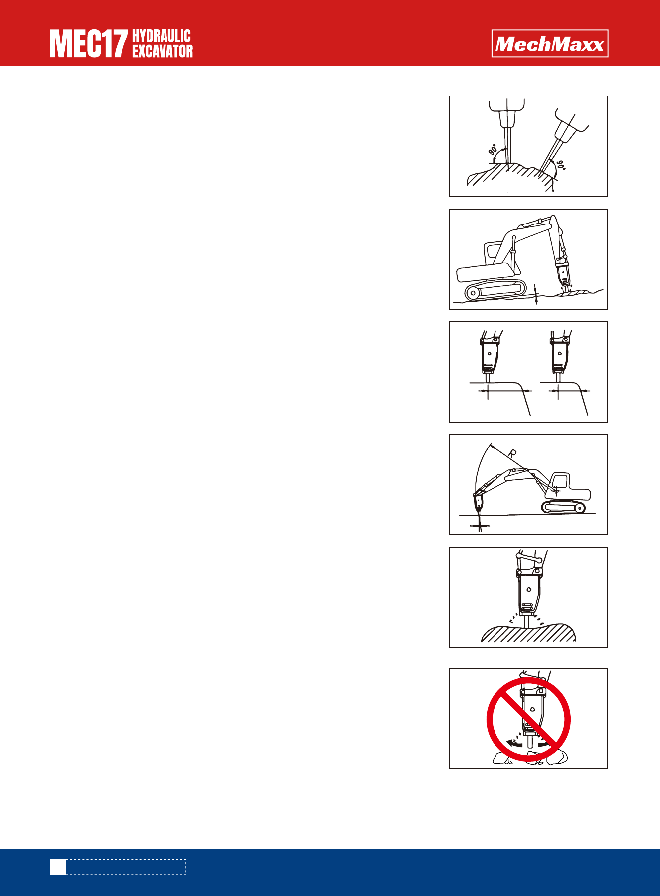
•The direction of penetration of the chisel and the direction of the breaker body will
gradually move out of line with each other, always adjust the bucket cylinder to
keep them aligned.
To ensure that the machine has a long life, and to ensure that operations are
carried out in safety, do not operate the machine in any of the following ways.
•Do not operate all cylinders to the end of their strokes. Always leave approx. 5
cm (2 in) to spare.
•Using the mount to gather in pieces of rock
•Always keep the chisel pressed against the impact surface properly to prevent
using the impact force when there is no resistance.
•Keep the chisel pushed perpendicularly against the impact surface when carrying
out breaking operations.
•When applying impact, push the chisel against the impact surface and operate so
that the chassis rises approx. 5 cm (2 in) off the ground. Do not let the machine
come further off the ground than this amount.
•When applying continuous impact to the same impact surface, if the chisel does
not penetrate or break the surface within 1 minute, change the point of impact and
carry out breaking operations closer to the edge.
Prohibited Works
www.mechmaxx.com
ATTACHMENTS AND OPTIONS
112
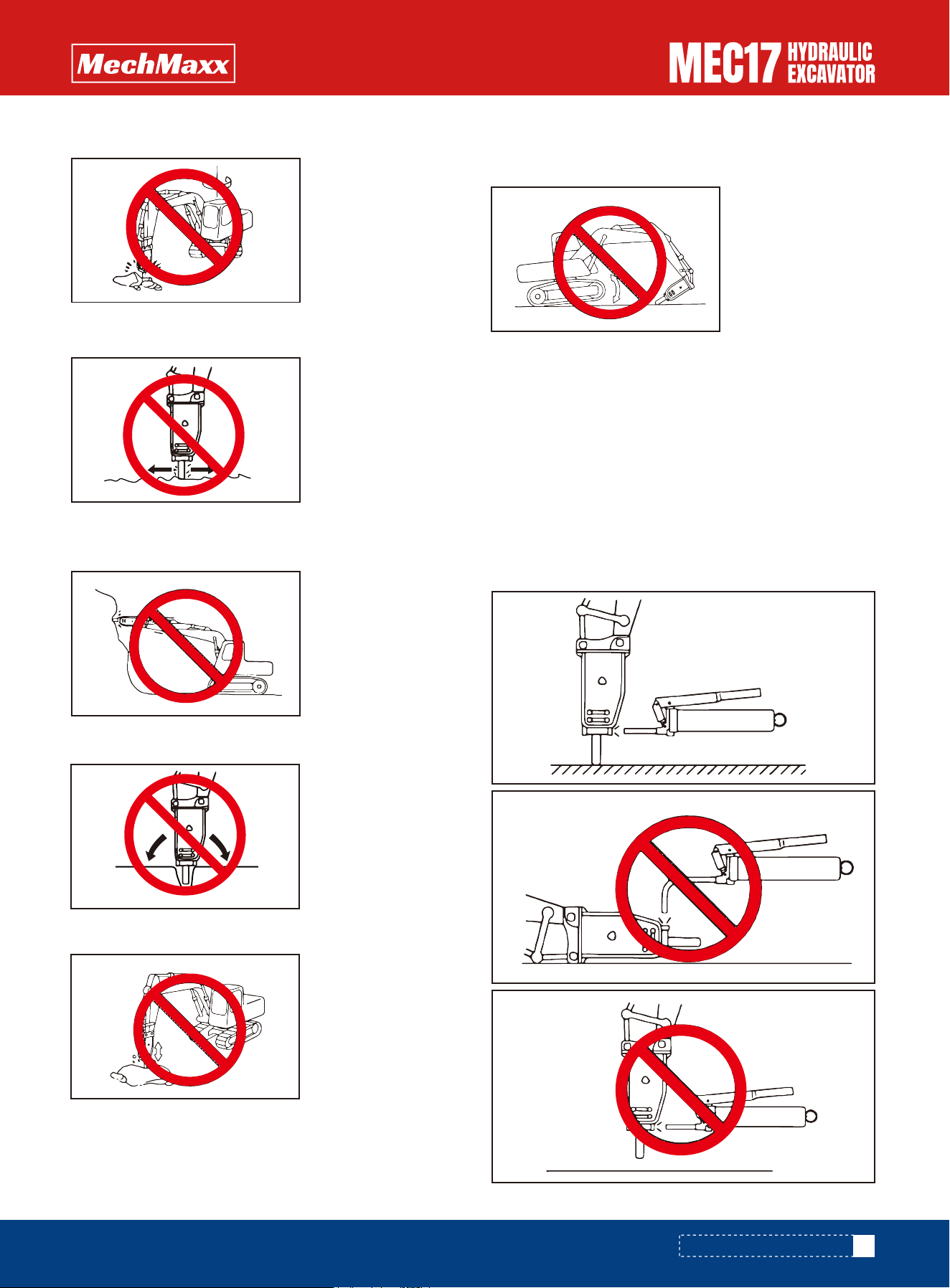
If the breaker is greased in an improper posture, it is filled
with more grease than necessary. As a result, soil and
sand will enter the hydraulic circuit and can damage the
hydraulic components, while the breaker is in use. There-
fore, be sure to grease the breaker, holding it in the right
posture.
Other specific steps refer to "Hydraulic Breaker Operation
and Maintenance Manual"
Supply Grease in the Correct Position
NOTICE
•Holding the chisel horizontal or pointed up when carrying
out impacting operations
•Twisting the chisel when it has penetrated the rock
•Pecking operation
•Extending the bucket cylinder fully and thrusting to raise
the machine off the ground
•Operations using the swing force
•Moving the chisel while carrying out impacting opera-
tions
www.mechmaxx.com
ATTACHMENTS AND OPTIONS
113