

Operator’s Manual
READ AND UNDERSTAND THE ENTIRE MANUAL BEFORE OPERATING MACHINE


TABLE OF CONTENTS
INTRODUCTION
SAFETY WARNING SIGNS
FRONT, REAR, LEFT, AND RIGHT
2
2
3
SAFETY
5
CONTROLS
23
4
SIGNAL WORDS
OPERATIONS
30
TRANSPORTATION 34
MAINTENANCE 35
TROUBLESHOOTING
40
PARAMETERS 42
ACCESSORIES
45
EXPLODED VIEW & PARTS LIST 46
30
BEFORE START OF OPERATIONS
30
START AND STOP OF ENGINE
31
OPERATIONS OF MACHINE
34
LOADING AND UNLOADING
35
OVERVIEW
36
SERVICE DATA
37
LIST OF WEARING PARTS
38
CRITICAL SAFETY PARTS
40
NO BATTERY POWER
41
RESTART AFTER REFUELING
41
FLASHING OF WARNING LAMPS
42
BASIC PARAMETERS
43
OVERALL DIMENSIONS OF MACHINE
44
OPERATING RANGE
45
PRECAUTIONS FOR OPERATIONS
45
PERIODICAL REPLACEMENT OF
HYDRAULIC OIL
37
PERIODICAL REPLACEMENT OF
HYDRAULIC OIL
3
FOREWORD
SERIAL NUMBER
3
4
DESIGNATED OPERATIONS
RUN-IN PERIOD
4
PRODUCT FEATURES
4
4
NOTES ABOUT READING OF THIS MANUAL
PRECAUTIONS DURING PREPARATIONS
7
GENERAL PRECAUTIONS
5
8
SAFETY MEASURES AT START
9
OPERATION PRECAUTIONS
13
PRECAUTIONS FOR PARKING
14
PRECAUTIONS DURING TRANSPORT
15
PRECAUTIONS FOR MAINTENANCE
20
SAFETY SIGNS
21
SIGN ON PRECAUTIONS
23
COMPONENT NAME
24
FUSE CASE, FUEL FILLING PORT, SEAT
24
SEAT
25
ELECTRICAL CONTROL PANEL
26
SWITCHES
26
JOYSTICKS AND PEDALS
28
ACCESSORY
1
TABLE OF CONTENTS
SAFETY WARNING SIGNS
SIGNAL WORDS
This sign denotes a safety warning.
The information behind the sign includes important safety information.
Please read and understand this information to prevent personal injuries or deaths. The machine owner or employer is
responsible for thoroughly instructing every operator on the correct and safe operation of all equipment. All personnel
operating this machine shall sufficiently understand the contents of this manual.
Before operating the machine, all operating personnel must receive the guidance on related functions of excavator.
Before operating this machine in a working site, learn and practice how to use the machine controls correctly in a safe
and spacious place.
Improper methods of operation, inspection,or maintenance can result in injury or death. Before any operation, checking,
or maintenance of machine, please read and understand this manual.
Please always carry this manual with you. It's preferable to preserve this manual on the machine.If this manual is lost or
damaged, please immediately order a new manual from a dealer. At the transfer of this machine, please ensure to hand
this manual over to the new owner.
The safety information on this manual and machine identifications is indicated by words "Danger", "Warning", and
"Notice". The meanings of these signal words are as below:
Important:
The word "Important" is intended to alert the operation and maintenance personnel of the possible damages
of machine and its components.
It's impossible for us to predict all possibly existed dangers. Therefore, the warnings in this manual or on this machine
can't cover all possible accidents. Therefore, during the operations of machine, ensure to take cautions and abide by all
conventional safety measures to prevent harms to machine, operating personnel, or other personnel.
“Danger” denotes high dangerous level, for which the negligence will result in death
or serious injury.
DANGER
“Warning” denotes medium danger level, for which the negligence will probably result
in death or serious injury.
WARNING
“Notice” denotes low danger level, for which the negligence will result in minor or
medium injuries.
NOTICE
2
SAFETY WARNING SIGNS
INTRODUCTION
FOREWORD
SERIAL NUMBER
This manual describes the operation, inspection, and maintenance of the machine, and the safety precautions to be
followed during operation.
·In some details, this manual probably differs from the manual attached on the machine in use.
·Please note that the information contained in this manual and the parameters of machine are subject to changes
without further notice.
Machine No. Engine No.:
3
INTRODUCTION

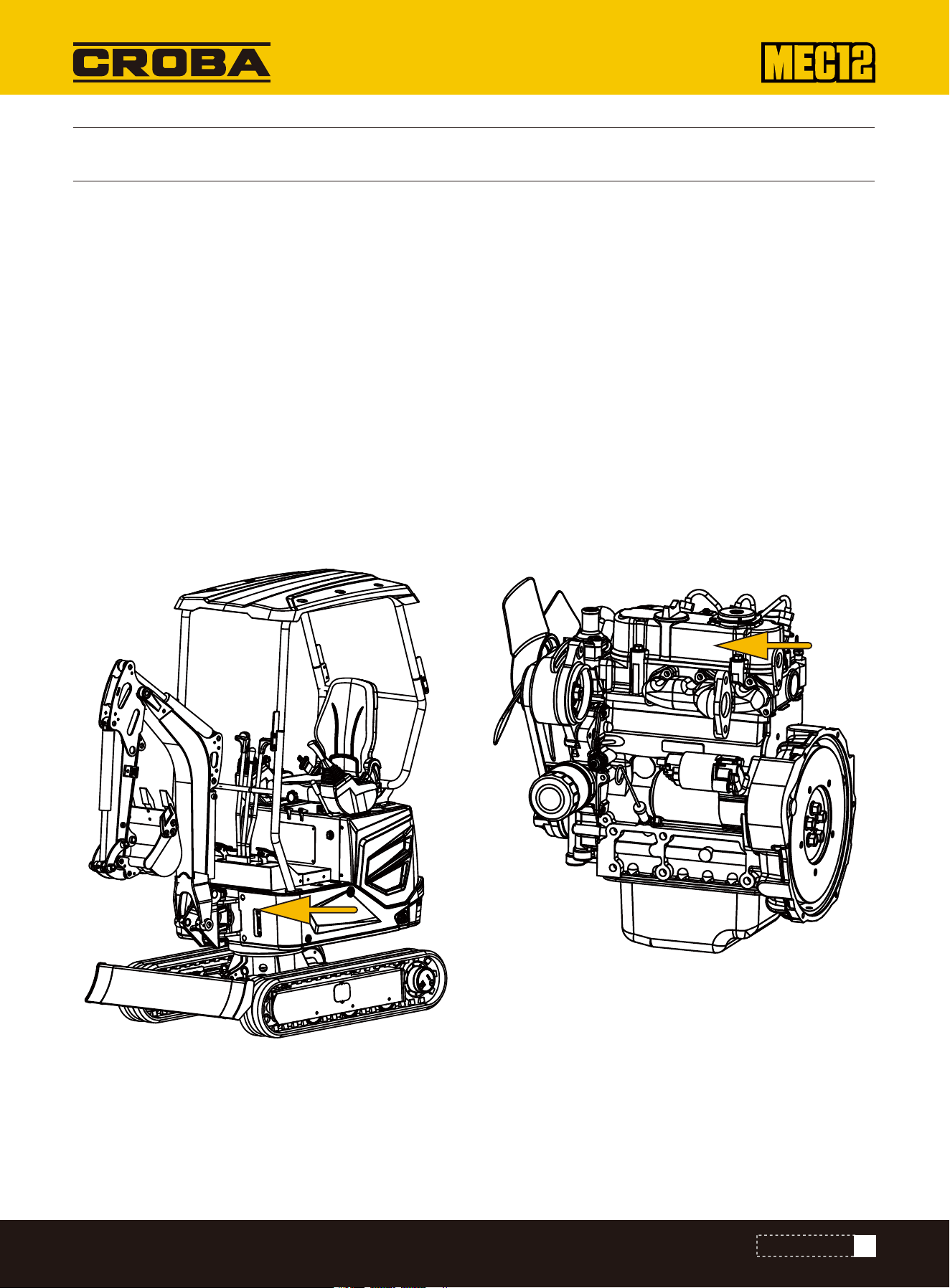
FRONT, REAR, LEFT, AND RIGHT
DESIGNATED OPERATIONS
PRODUCT FEATURES
RUN-IN PERIOD
The front, rear, left, and right of the machine indicated in this manual are
based on the status sitting in the driver seat, with the bulldozing blade
visible in the front.
For the first 100 hours of use (the break-in period), follow these instructions. Operating a new machine without a proper
break-in can reduce acceleration performance and may shorten the machine's life.
·Sufficiently warm up the engine and hydraulic oil.
·Avoid heavy-load and rapid operations. Maintain the load at approximately 80%of maximum load capacity during opera-
tions.
·Do not start, accelerate, steer, or stop suddenly, unless it's really necessary.
This machine is mainly applied for following operations:
Digging
Ditching
Side ditching
Leveling
Loading
Small size, flexible operation.
Can be equipped with a variety of attachments.
Track width "flexible machine width structure".
Front
Right
Rear
Left
4
INTRODUCTION
GENERAL PRECAUTIONS
SAFETY
You are responsible for abiding by all applicable safety laws and regulations and for properly operating, inspecting, and
maintaining the machine.
As a matter of fact, allaccidents are caused by the non-compliance with basic safety rules and precautions. Most
accidents can be avoided by identifying potential hazards in advance.
Please read and understand all safety information related to the prevention of accidents. Operate the machine only after
you fully understand how to operate it, inspect it, and maintain it.
During the operations, checking, or maintenance of machine, upon detection of any machine abnormality (Such as unusu-
al noise or vibration, odors, abnormal instrument readings, smoke or oil leaks, error warnings, and abnormal display on the
control panel), immediately notify a sales or service dealer and take appropriate measure. Do not operate the machine
before the abnormality is solved.
To maintain the performances and prevent the earlier wear of machine,please abide by the following operating conditions.
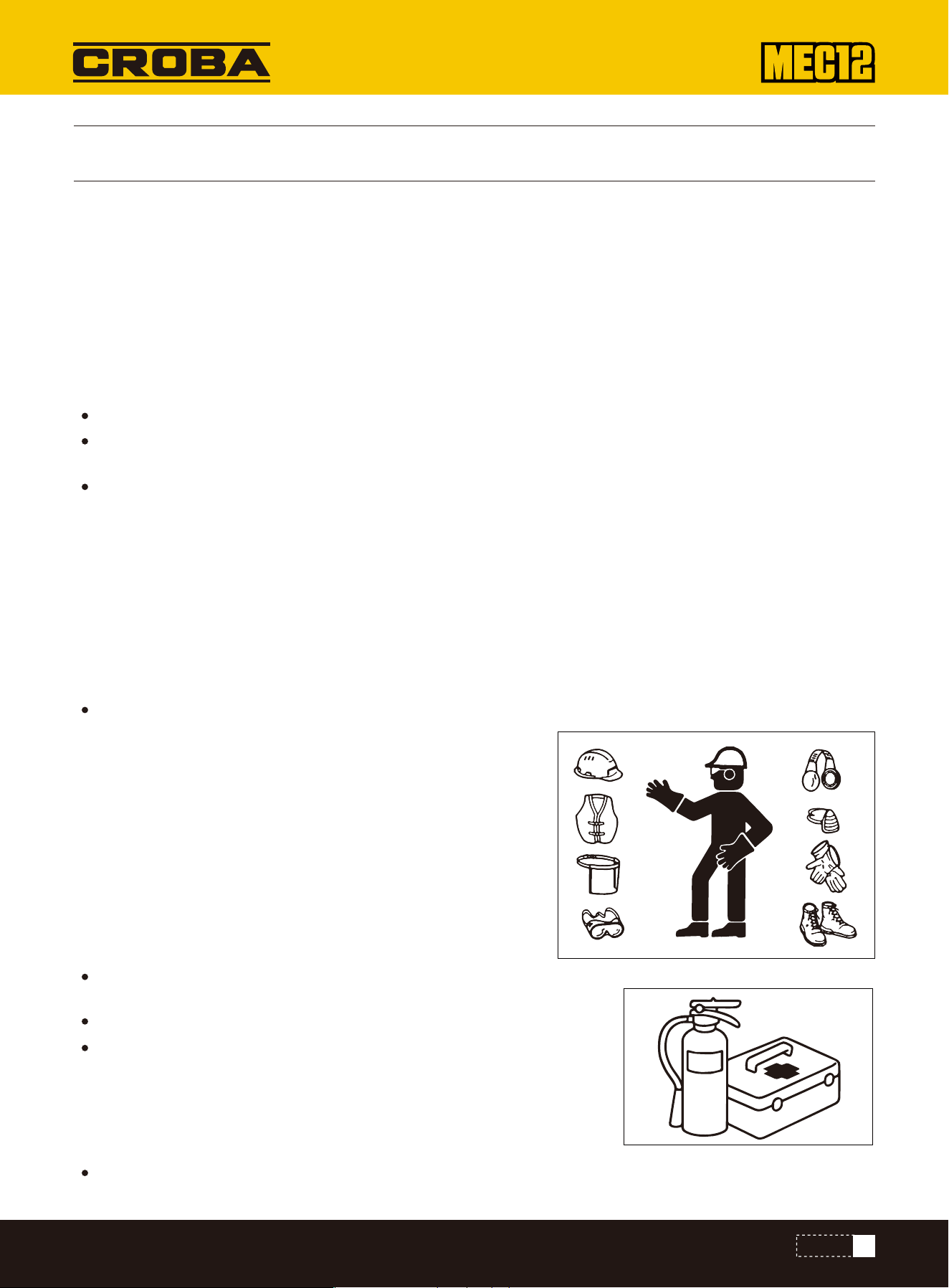
Appropriate Clothing and Personal Protective Equipment
Abiding by All Safety Regulations
Upon detection of machine abnormality
Operating Temperature Range
The machine must be operated, checked, and maintained by trained and qualified personnel.
During the operations, checking,and maintenance of machine,ensure to understand and abide by all rules, regulations,
precautions, and safety measures.
Do not operate, check, or maintain the machine under the adverse influence of alcohol, drug, medicine, or fatigue or
under sleepy status.
Do not operate the machine when the outside temperature is above + 113°F (+45℃) or below + 5°F (-15℃).
Operating the machine above + 113°F (+45℃) can cause the
engine to overheat and reduce engine performance. Additionally, the
hydraulic oil can become excessively hot and damage the hydraulic
system. Operating the machine below + 5°F (-15℃) can harden
rubber components (such as seals) and cause premature wear or
damage. If you need to operate the machine outside this tempera-
ture range, consult your dealer.
Do not wear loose clothing or wear decorative articles that will probably hitch
to any joystick or motion part.
Do not wear clothing contaminated with oil or gasoline, as it is flammable.
As required by the work environment, wear safety shoesa helmet, safety
goggles, a ilter mask (respirator), thick gloves, hearing protection (earplugs or
earmuffs), and other protective equipment. When using a grinder, breaker
hammer (or other powered tools like compressed air), wear appropriate
protective equipment such as safety goggles and a filter mask. Flying metal
chips or debris can cause serious injury.
Wear hearing protection during machine operation. Prolonged exposure to high
noise levels can cause hearing damage or even complete hearing loss
5
SAFETY

Learn how to use the gestures of specific operation needs and designate the person responsible for making gestures.
Install a fire extinguisher and a first-aid kit on the machine, and
ensure you know how to use both properly.
Learn how to extinguish fre and handle accident.
Know how to contact emergency aid and fabricate the emergency
contact list.
Please ensure that all guardrails, shelters, and doors are installed
properly and securely. Before operating the machine, please repair or
replace damaged parts.
Know how to use safety lock handle, seat belt, and other safety
devices and understand the correct operation methods.
Do not disassemble any safety device,unless for the purpose of
checking and repair. Always keep all safety devices under good work-
ing condition.
All personnel must completely understand all gestures.
The operator must respond to the gestures of designated person only.Howeverthe operator must abide by the stop
gesture made by anyone in all cases.
The signaler must stand in a clearly visible place while making the gestures.
Before standing up from the driver seat to open/close windows or disassemble/install
the lower window, lower the working device onto the ground lift up and lock the safety
lock handle, and stop the engine. When the safety lock handle is lowered down
(Unlocked), the accidental touch of any joystick will result in sudden movement of
machine and cause serious injuries or deaths.
Please note that, even if the safety lock handle is placed at locking position, the
bulldozing blade, boom, and auxiliary hydraulic controls can't be locked. Do not touch
such controls accidentally.
When raising or lowering the safety lock handle, be careful not to touch any joystick.
Before leaving the driver's seat, lower the attachment to the ground, lift the safety
lock handle to the locked position, and shut off the engine. Also, be sure to remove the
key, close all doors and hoods, and keep the key with you in a designated safe place.
Keep fuel, oil, grease, and antifreeze away from flame. Fuel is highly flammable and extremely dangerous. Handle these
flammable liquids away from lit cigarettes, matches, lighters,and other sources of flame or sparks. Do not smoke or use
open fire while handling fuel or performing the operations of fuel system. Do not leave the area while refueling or adding
oil.
Do not remove the fuel tank cap or refuel while the engine is running or until it has cooled down. In addition, Do not spill
fuel onto any hot surface of the machine or onto any electrical component.
Installation of Fire Extinguisher and First-Aid Kit Fulfill the prepara-
tions for fire and accident.
No Disassembling of Safety Devices
Setup of Signaler and Flagman
Precautions for Standing up from or Leaving Driver Seat
Guard against Fire and Explosion Dangers
6
SAFETY

PRECAUTIONS DURING PREPARATIONS
Immediately clean up any spilled fuel or oil thoroughly
Check for any fuel or oilleaks. Fix any leaks and clean the machine before operating. Move any flammable materials to a
safe place before grinding, cutting, or welding.
Do not cut or weld any pipe that may contain flammable liquids. Thoroughly clean it with a nonflammable cleaning
solution before welding or cutting.
Remove all wastes and impurities from machine. Ensure that there is no oil contaminated rag or other inflammable on
the machine.
Handle all solvents and dry chemicals (Foam fire extinguishe) as per the manufacturer's procedures indicated on the
containers. Operate in a well-ventilated place.
Never use fuel for cleaning purpose. Always use non-inflammable solvent.
Please open doors and windows for thorough ventilation during the handling of fuel and the cleaning of oil stain or paint.
Preserve all inflammable liquids and materials in a safe and well-ventilated place.
The short-circuit of electric system will probably result in fire. Daily check the wire connections for looseness and
damage. Re-tighten loose connections and cable clamps. Repair or replace damaged wires.
Before starting work, understand the conditions of the work zone to ensure safety.
•Check the terrain and ground conditions in the work area. For indoor operations,
check the building structure and when necessary take safety measures.
•Make sure to stay away from hazards and obstacles such as open ditches, under-
ground pipelines, trees, cliffs, overhead cables, and roads in areas prone to falling
rocks or landslides.
•Locate any underground gas lines, water pipes, or electrical cables in consultation
with the site administrator. If necessary,discuss with the administrator to deter-
mine what safety measures are needed to be taken to ensure safety.
•When operating on a road,be sure to consider the safety of pedestrians and other
vehicles.
•Use a signaler and/or signals.
•Isolate the working zone against the access of non-authorized personnel.
•Before operations in water or driving through shallow rivers, check the water depth-
ground firmness, and flow rate in advance. Understand more operation description
information with reference to the "Precautions during Operations"
Please check the permissible load before driving on bridges or structures. If the
strength is insufficient, reinforce the bridges or structures.
Toxic Exhaust Gas from Engine
Understanding of working zone
Checking of Bridge Strength
Fire accident caused by pipelines: Ensure that the clamps,protection devices,and cushion pads of hoses and pipes
are securely fixed. In event of looseness, the hoses and pipes willbe damaged due to vibration or contact with other
parts during operations. This willprobably result in spray of high pressure oil to cause fire accident or harms.
Do not operate the engine in an enclosed place with poor ventilation.
If the natural ventilation is not possible, install ventilation fan, fan, extended exhaust pipe, or other ventilation device.
7
SAFETY
SAFETY MEASURES AT START
•Eliminate all loose objects and unnecessary devices in the machine.
•Wipe away lubricating oil, grease, mud, snow, and ice, in order to prevent accident due to slip.
•Remove dusts, lubricating oil, and grease from engine portion to prevent fire accident.
•Clean the area around operator's seat and remove all unnecessary objects from the machine.
Always Keeping Clean Machine
The failure to find out or repair the abnormalities or damages of machine will cause
accidents.
•Before operations, fulfill the designated checking and when necessary repairimmediate-
ly
•In event of operation failure due to malfunction or engine malfunction, immediately stop
the engine as per stop procedure and park the machine securely, till the malfunction is
repaired. Precautions within Cab (If installed)
•Before entering the cab, wipe offany mud or grease from your shoe soles. Operating the
pedals with muddy or greasy shoes can cause you to slip and result in an accident.
•Do not leave any parts or tools lying around the driver's seat.
•Do not use a mobile phone while driving or operating the machine.
•Do not bring any flammable or explosive materials into the cab.
•Do not leave a lighter in the cab,as it could explode if the interior temperature rises.
Support your body weight by three-point safety posture while getting on/off the machine.
•Do not jump on or off the machine. Do not attempt to get on or off a moving machine.
•Always face the machine when climbing up or down.Use the steps/footplates and grab
the handrails, maintaining three points of contact (for example, two hands and one
foot).
•Do not use the safety lock handle or any joystick as a handhold.
•Before starting the machine,keep all non-authorized personnel away from this zone.
Start the engine only after the safe start is confirmed by checking the following items.
•Walk around the machine and alert any maintenance personnel or bystanders neaby.
Start the engine only after confirming that no one is in the vicinity.
•Sound the horn to alert any people nearby.
•Adjust the seat until it locks securely.
•Fasten the seat belt.
•Ensure the parking brake is engaged and all control levers and pedals are in neutral.
•Verify that the safety lock handle is in the locked position.
•Make sure no one is near the machine.
•Start and operate the machine only from the driver's seat.
•Do not attempt to start the engine by short-circuiting the starter's terminals.
Daily Checking and Maintenance
Sit in the driver's seat and start the engine.
8
SAFETY
OPERATION PRECAUTIONS
Start by Jumper Cable
After Start of Engine
Operating Machine with Maximum Track Width
Guarantee of Good Visibility
Do not carry people on the machine
For Cold Weathers
Jump-Starting — Always use the recommended procedure when jump-starting the machine. Incorrect use of jumper
cables may cause a battery explosion or unexpected machine movement.
For detailed instructions, refer to the section “In the Event of No Battery Power.”
After starting the engine, perform the following operations and checks in an area clear of people
and obstacles. If any malfunction is detected, shut down the engine according to the proper
procedure and report the issue.
Warm up the engine and hydraulic oil. Check that all gauges and warning lights are functioning
normally, and listen for any unusual noises. Test the engine speed control. Operate each control
lever and pedal to ensure everything is functioning properly.
Be cautious of slippery conditions: frozen ground, footplates, and handrails can be slick. In cold weather, do not touch any
metal part of the machine with bare hands—your skin could freeze to the metal and cause serious injury.
Do not use ethyl ether or starting fluid on the engine. The starting fluid can cause explosion and serious injuries or deaths.
Warm up the engine and hydraulic oil.
Operating joysticks without warm-up will result in slow or inappropriate reaction or movement of machine to cause
accident.
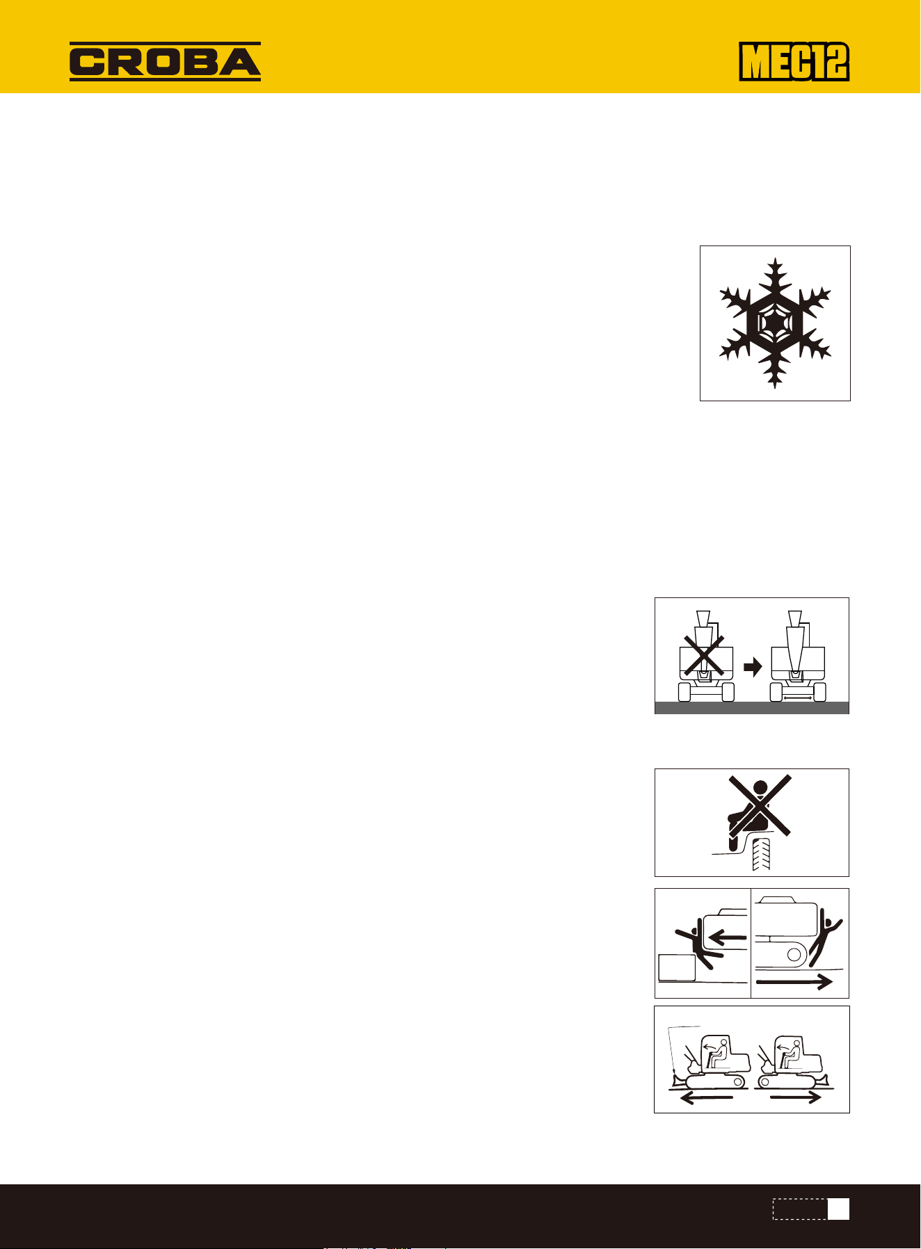
Always operate the machine with extended track width (42.7 inchs), in order to improve
the machine stability to the maximum extent. Operating the machine with narrow track
width (34.6 inchs) will probably result in rollover of machine due to poor stability.
If it's necessary to operate the machine with narrow track width (34.6 inchs), retract the
bucket working device and lower
the boom to reduce the gravity center and face the machine towards front before travel-
ing.
Checking of Visibility before Operations of Machine
During operations in a dark place, turn on the working lamp and headlamp of machine and
when necessary install additional lighting devices. In event of poor visibility due to severe
weathers (Such as fog, snow, rain, and haze), stop the operations of machine till the
visibility turns good.
Clean the windowsmirrors, lamps, and camera to keep good visibility.
Adjust the mirrors and camera to optimal positions to ensure that the driver sitting in the
driver seat can see the rear view (Blind spot). The non-authorized modification or the
installation of non-approved attachments willprobably mpair the visibility. The operator's
visibility must conform to the require- ments of ISO 5006.
All personnel are prohibited to sit on any part of machine at any time during traveling Or
operations of machine.
Bulldozing blade
9
SAFETY
Checking for Safe and Reliable Working Zone before Operations
Checking of Chassis (Tracks)before Traveling
Safe Traveling
Precautions for Traveling on Slopes
Verify the performance limits of machine.
Set up a signaler at the road shoulders, narrow places, or vision-obstructed
places. Do not allow any person to access the turning radius or path of machine.
Sound the horn to indicate your movement intention. There are blind zones
behind the machine.
Before driving backward, check the safety in the area behind machine and
ensure there is no person behind the machine.
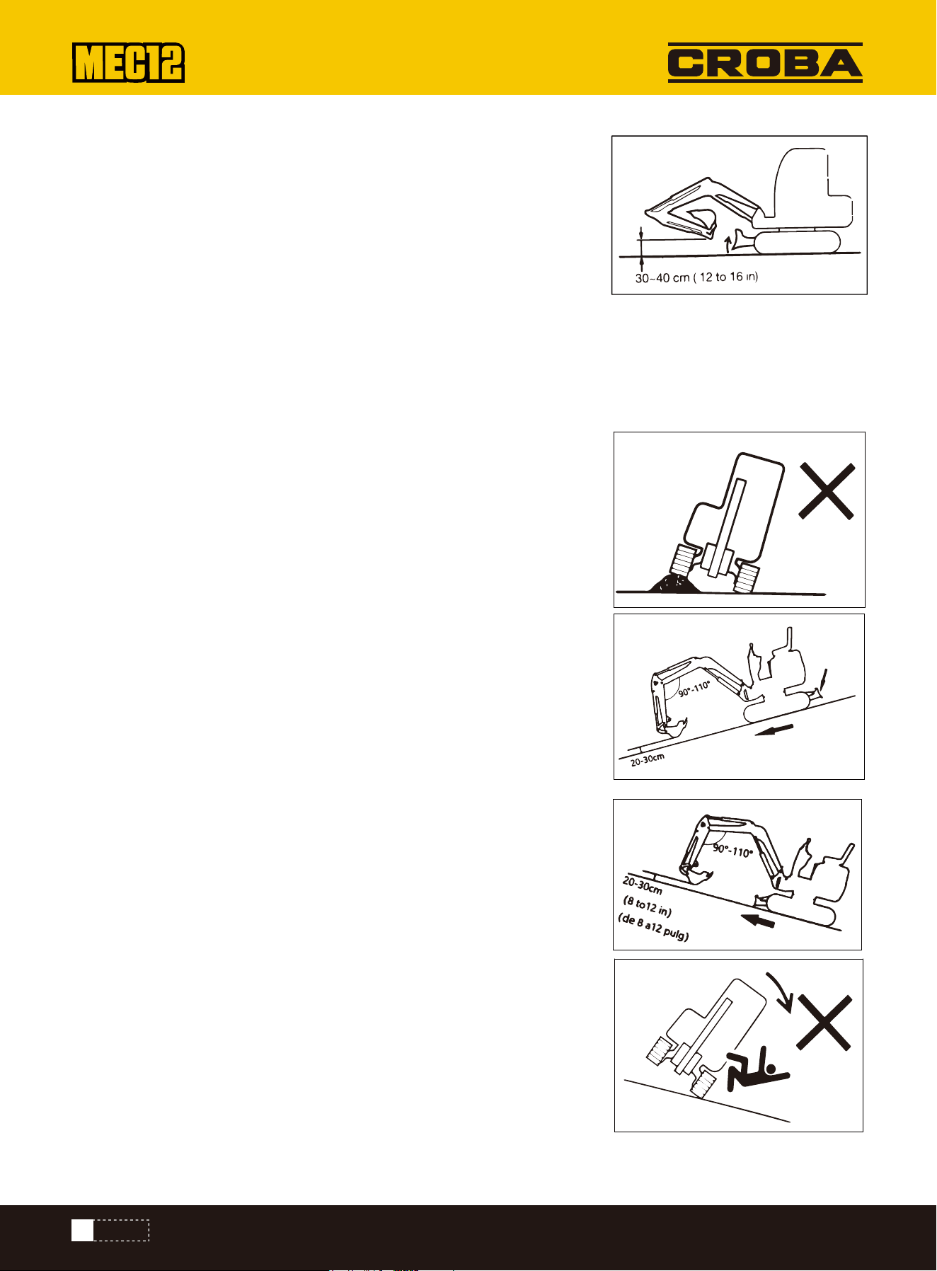
The bulldozing blade shall be lifted during traveling. Retract the bucket working
device as shown in above diagram and lift the bucket by 8 to 12 inchs off the
ground.
Do not slew during the traveling. If it's necessary to operate the bucket working
device during traveling, operate at sufficiently low speed to ensure the complete
control at all times.
Avoid driving over obstacles whenever possible. If it's necessary to drive over
obstacles, keep the bucket operating device near the ground and travel at low
speed. Do not drive over any obstacle that will incline the machine by 10° or
larger. On rugged roads,drive the machine at low speed and avoid the sudden
startup, stop, and direction change. Otherwise, the working device will probably
come into contact with the ground to cause unbalance and damage of machine
or destruct the structure in surrounding area.
While traveling on slopestake cautions to prevent the rollover and gliding of
machine.
Do not drive the machine on a slope steep enough to cause instability of
machine. Please note that, in the actual applications, the performances of
machine on a slope willbe deteriorated due to severe working conditions.
Keep the driver seat facing towards the up slope direction while climbing up a
slope. Keep the driver seat facing towards the down slope direction during down
slope traveling. In both cases, pay special attention to the ground ahead of the
machine during traveling.
While traveling on a slope,lower the bucket to 8 to 12 inchs off the ground.
While climbing up a steep slope, extend the bucket working device to the front
position. In event of an emergency, lower the bucket onto the ground and stop
the engine of machine.
When walking on slopes or ramps,drive slowly. Reduce engine speed when going
downhill. Do not reverse the machine down a slope.
Do not change direction on slopes or cross slopes. First return to the flat
surface, and then take another path.
When walking on a gentle slope covered with grass or dead leaves,or when walk-
ing on wet metal plates or frozen ground, the machine may slip. Make sure that
the machine does not stop laterally on a slope. If the machine stalls on a slope,
return the operating levers to the neutral position, and then restart the engine.
Before operating the traveling joystick/pedal, ensure that the bulldozing blade is in front of the driver seat. Please bear in
mind that the operation direction of the traveling joystick/pedal with bulldozing blade behind the driver seat is reverse to
that with bulldozing blade in front of driver seat.
Downhill
Bulldozing
blade
10
SAFETY
Special Cautions for Operations of Machine on Ice/Snow
No Movement of Bucket over Personnel
While traveling on snowy or icy roads,drive at low speed and avoid the sudden startup, stop, and direction change.
In snowy regions, the road curbs and the roadside objects are buried in the snow to become invisible. In addition, there is
a danger of machine rollover or collision with covered objects. Therefore,always operate with cautions.
There is a danger of rollover or snow entrapment while driving the machine into thick snow. Drive with cautions and do
not drive over road curbs or entrap in the snow.
For frozen soil surface, the ground becomes soft when the temperature rises, which willprobably result in rollover of
machine and entrapment of operator in the machine.
While parking the machine on a unstable ground, lower the bulldozing blade.
Moving the bucket over the personnel has a danger of splashing of loaded material or the sudden falling of bucket.
Guarantee of Driver's Safety during Loading
Keeping a Safe Distance from Overhead High-Voltage Cables
Close Observation on Dangerous Working Conditions
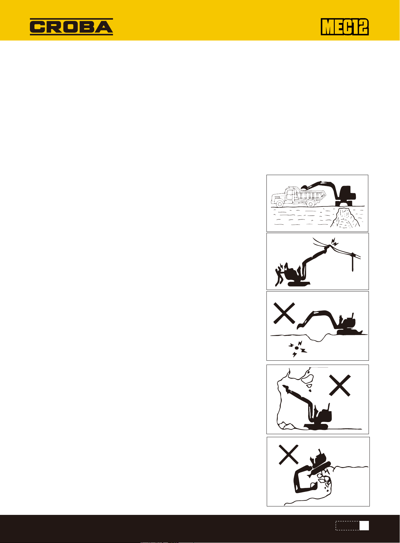
Do not load before the driver reaches a safe place. Do not swing or
position bucket above personnel or cab. Load from the backdoor of
trucks.
Never close any part or loaded material of machine to high-voltage cables unless
all safety measures specified by local and national authorities are already taken.
There is a danger of electric shock and death when any person approaches to the
machine that is discharging electric spark or is near or in contact with power
supply.
Always keep a safe spacing between machine and high-voltage cables. Before
starting operations, please verify the relevant operation safety procedures with
local power grid.
Consider all electric cables as high-voltage cables. Even if it's known or believed
tha the power supplyis cut off or the cable is clearly grounded, consider such
cables also as live cables.
If the machine is too close to high-voltage cables, set up a signaler to sound warn-
ings. Keep all personnel within operation zone away from machine and loaded
material.
Pay special attention to the underground high-voltage cables.
Never dig on the bottom of any high embankment.It's really dangerous because
such operation will probably result in surface collapse.
Do not operate in any place with falling stone danger.
Keep a safe spacing between machine and edge of digging site. Do not dig the
ground ahead of machine.
During the operations near a cliff or road curb, to ease the escape in any event,
form a right-angle between tracks and cliff or road curb and place bulldozing blade
in the front.
Do not access any soft ground area. This will probably result in inclination of
machine due to dead weight to cause rollover or ground entrapment.
Keep away from unstable ground (Cliffs, road curbs, and deep ditches). If the
ground collapses due to machine weight or vibration, there is a possible danger of
machine falling or rollover. Please bear in mind that the soil turns infirm after
heavy rain or exploson.
11
SAFETY
Danger during Operations on Slopes
No Lateral Slewing (Swing) with Bucket Heavily Loaded
Please pay attention to the objects above your head
Not Designed for Lifting Application
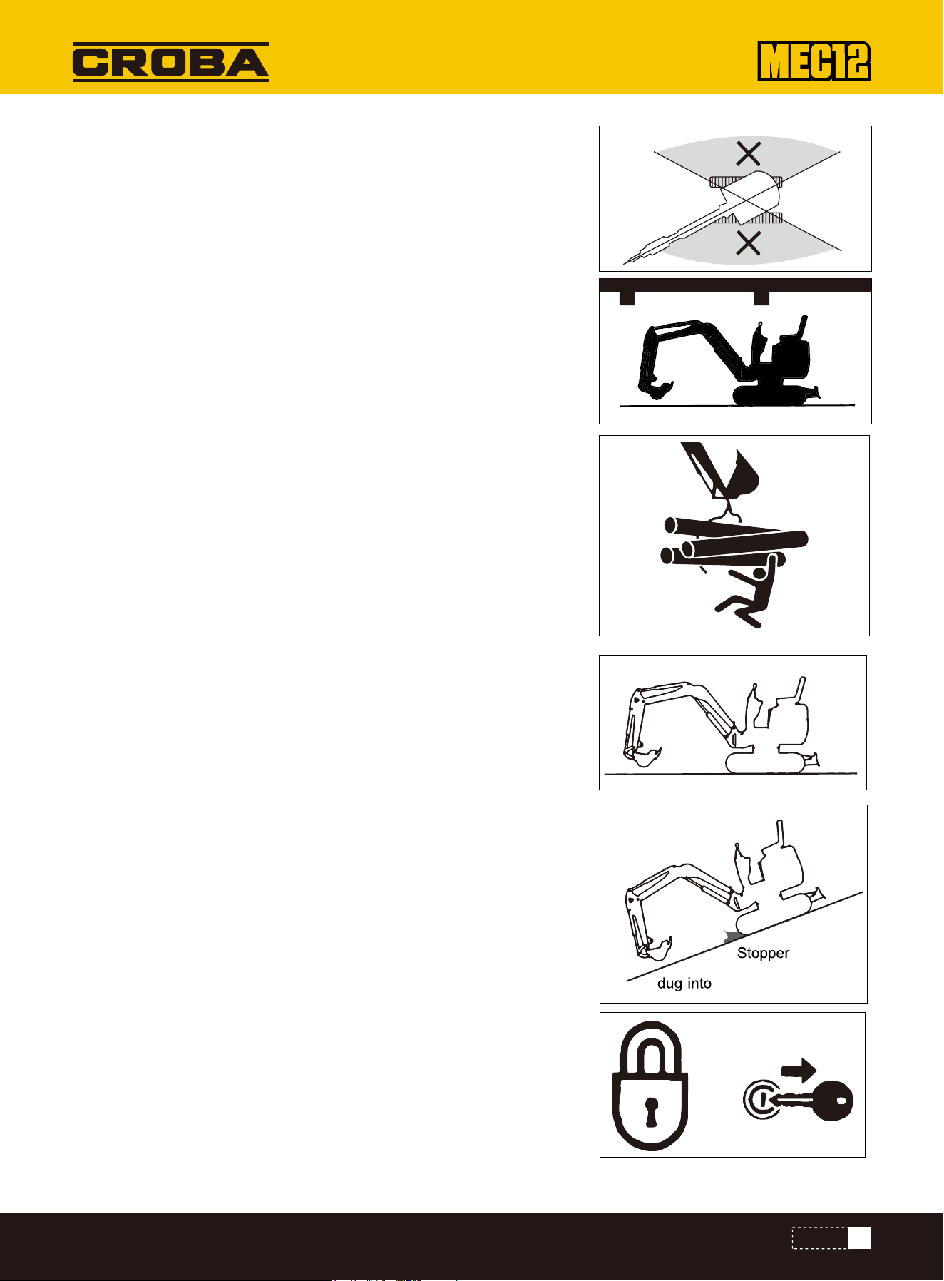
The ground on the top of embankment and the ground around and on top of the dug
ditches are also infirm.
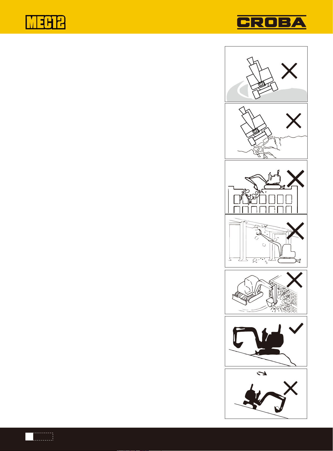
Do not perform demolition operations beneath the machine. There is a possible
falling danger of machine when the ground becomes unstable. Before the operations
on the top of any building or other structure, check the strength and structure. It will
cause serious harms or destruction if the building or structure collapses.
Do not perform demolition operations above your head. There is a falling damage of
damaged parts or collapse danger of building to cause serious harms or destruction.
Do not perform the demolition operations by the impact force of bucket working
device.The splashed material fragments and the damaged bucket working device
have a danger of serious harms
During operations on slopes,slewing or operating the working device can probably
result in instability or rollover of machine.
Avoid operations on slopes whenever possible.
Leveling operation zone
If the bucket is fully loaded with material, avoid slewing towards the down slope
direction. Otherwise, it will deteriorate the machine stability and probably result in
rollover
The machine is more vulnerable to rollover in lateral direction than longitudinal direc-
tion. Do not laterally slew (swing) when the bucket working device is heavily loaded.
Especially, do not laterally slew (swing) on a slopeWhen the machine is equipped
with breaking hammer, grinder, or extended bucket arm, the attachment end is
heavier than that with standard bucket. For machine with such heavy end, do not
face the bucket arm (boom) towards down slope direction for digging or towards
lateral direction for operations.
During operations under bridges, in tunnels, near cables, or indoors, guard the boom
and bucket arm against impact with any overhead object
This machine is specially designed for digging operations. Therefore, it's not nstalled
with safety devices for lifting operations. Take special cautions while using this
excavator forlifting operations.
Do not overload during lifting. The overload will result in rollover of machine to cause
serious injuries or deaths.
Allrated lifting capacities are based on the condition of using this machine on a firm
and level ground. The user's is recommended to reserve an appropriate allowance for
specific working conditions, in order to ensure the safe lifting operations. The soft
or uneven ground, non-level status,lateral load, dynamic or sudden load, dangerous
environment, and personnel experience are included. Before operating the machine,
the operating personnel and other personnel shall be really familiar with the Opera-
tion Manual. The safe operation regulations of the machine shall be strictly followed
in all cases. If the chain or lifting device is incorrectly connected,the bucket
connecting rod or the lifting device will probably fail to cause serious injuries or
deaths.
Landfill
12
SAFETY
While using this machine as a crane, do not attempt to pullout a stump from
the ground. For this application, the load applied onto the machine is
completely unknown. Do not allow any person to stand on or beneath the lifted
object or close to the operation zone
Please pay attention to flying objects
Safe parking
Precautions for Towing
This machine is not installed with any protective device to guard the operator
against the harms of flying objects. Do not operate this machine in any
dangerous place in which the operator is probably subject to the impact of
flying objects.
During towing, the improper operations, the incorrect use of rope, or the
improper checking will cause serious injuries or deaths.
The breakage or cracking of rope can cause danger. Use wire ropes compatible
with the towing force. Do not use any kinked, twisted, or even damaged rope.
Do not suddenly apply heavy load onto the rope.
Please wear safety gloves during the handling of rope.
Ensure that an operator is assigned each on the towing machine and the
towed machine. Do not operate the towing operation on a slope. Keep all
personnel away from the rope during towing. Please refer to the section
"Towing" to understand more description information.
•Park the machine on firm, level ground and engage the parking brake.
•If you must park on a slope (or tilt the machine on a slope), make sure the
machine is secure and block/chock it to prevent movement. If parking the
machine on a road or street, use barricades, cones, warning signs, or lights
to keep it visible even at night and to prevent collisions with other vehicles.
•Complete these steps before leaving the machine: lower the bucket and
blade to the ground, raise the safety lock handle to the locked position, shut
off the engine and remove the key, then lock the cab and hood and take the
key with you.
PRECAUTIONS FOR PARKING
13
SAFETY
Safe loading/unlocking of machinelying objects
Safe Lifting of Machine
The machine will probably roll over or fall off during loading and unloading. Be sure to take the following safety measures:
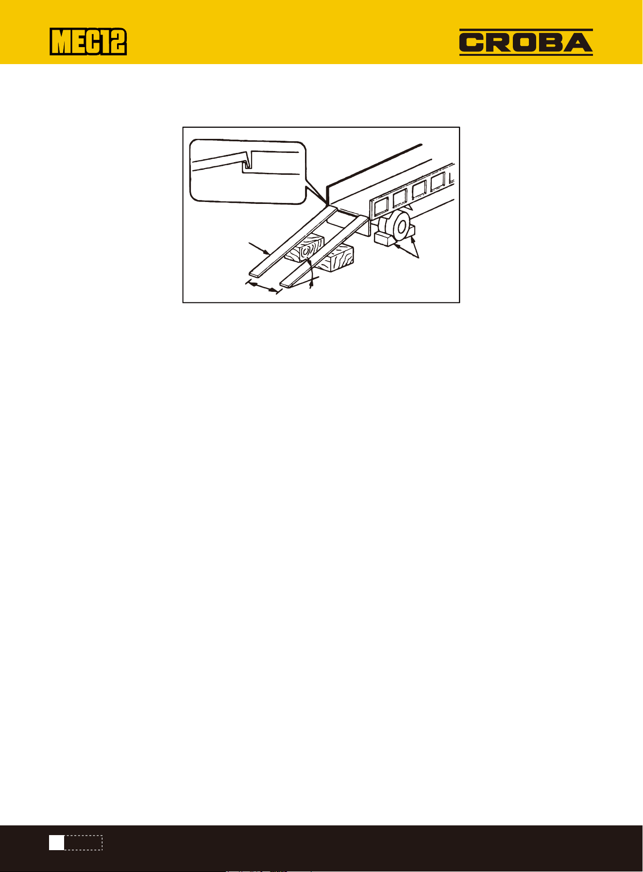
Select a solid and level ground and keep a sufficient spacing from the road curb. Secure loading ramps of adequate
strength and size to the truck's bed.
The ramp incline must not exceed 15°. If the ramps bend or sag excessively, support them with blocks or stands.
Do not attempt to load or unload the machine using its boom or attachments. Doing so could cause the machine to
rollover or falloff the trailer.
Keep the truck bed and ramps clean and free of oil, sand, ice, snow, or other debris to prevent the machine from sliding.
Also, clean the tracks before loading.
Chock the transport truck's wheels with wedges to prevent movement. When loading or unloading, drive the machine
slowly in first gear (low speed) and follow the signals of a spotter.
Do not turn or change direction on the ramps. Do not swing (rotate) the machine while on the ramps, or it may rollover.
Slewing (swinging) the machine on the cargo body of the truck willprobably result in unstable legs of the machine. There-
fore,operate slowly.
Chock the tracks securely with wedges, then tie down the machine to the truck bed with ropes or chains.
Use the proper hand signals when ifting the machine.
Check the lifting equipment daily for any damaged or missing parts, and replace components if necessary. Use slings or
chains with suffcient rated capacity for the machine's weight when lifting
Lift the machine according to the procedure described below. Do not use any other method, or the machine may become
unbalanced. Refer to the 'Lifting of Machine'section for more information. Do not lift the machine if anyone is stillon it.
Lift slowly to prevent the machine from tipping over. While lifting, keep all personnel away from the work zone, and never
move a suspended machine over a person.
Safe Transport of Machine
During transport,abide by all applicable safety rules,vehicle codes, and traffic laws. Consider the combined length, width,
height, and weight of the transport truck and loaded machine when selecting a route.
Do not accelerate or brake the transport truck suddenly, and avoid driving at high speed. Such actions could cause the
loaded machine to shift or become unstable.
Stop block
15°or less
Distance
between
Ramp
Fix to suspension
parts
PRECAUTIONS DURING TRANSPORT
14
SAFETY
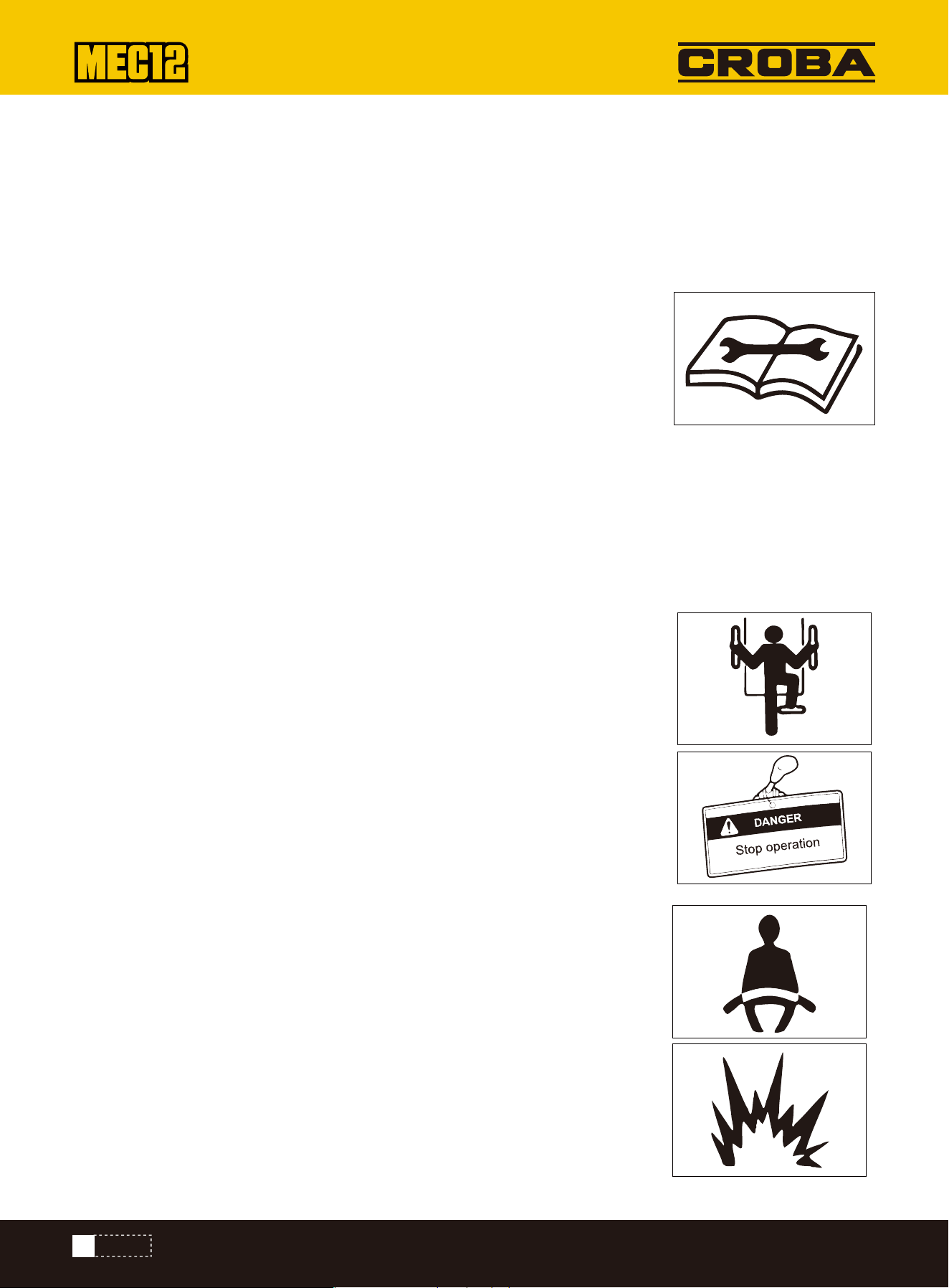
Warning Information of "No Operation" Sign
Use of Correct Tools
Periodically Replaced Critical Safety Pats
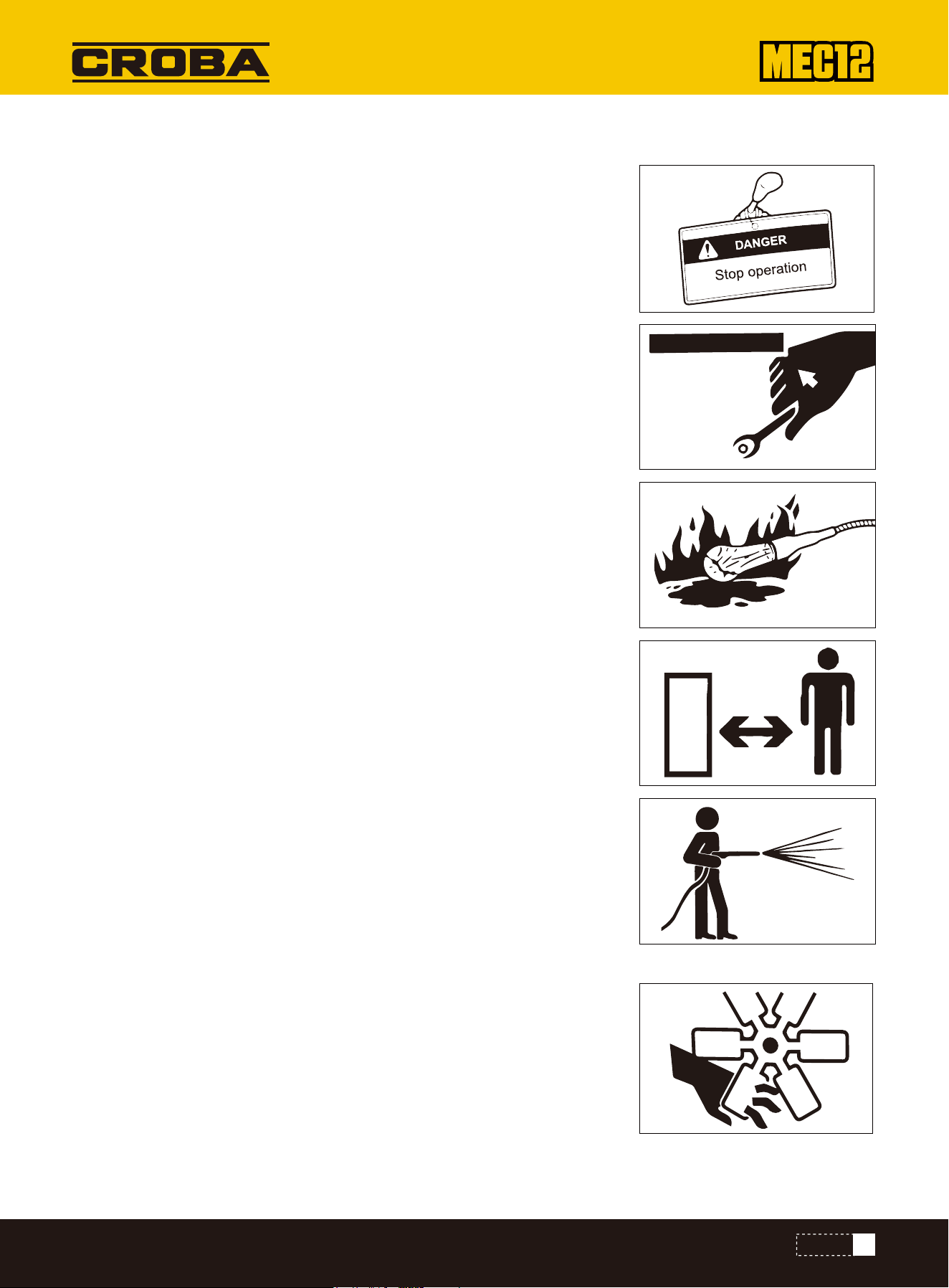
While someone is inspecting or servicing the machine,an unauthorized person
starting the engine or moving a control lever could cause a serious injury.
Before performing maintenance,shut off the engine and remove the key, keeping it
with you.
Affix a "Do Not Operate" warning tag in a highly visible place, such as on the ignition
switch or on a joystick.
Do not use damaged or worn-out tools, or any tool that is not intended for the job
.Always use tools that are proper for the maintenance task.
Replace the fuel hoses at regular intervals. Fuel hoses deteriorate over time, even
if no obvious damage is visible. If you see any signs of wear, replace the hose
immediately, regardless of the normal schedule. For more details, refer to the
section "List of Critical Safety Parts."
Explosion-Proof Lamps
While checking the fuel, lubricating oil, coolant,and battery electrolyte, always use
explosion-proof work ights to prevent igniting fumes. Failure to do so could result
in an explosion, causing serious injury.
No Access of Non-Authorized Personnel
During operations, the non-authorized personnel are prohibited to access the work-
ing zone. Take cautions during grinding ,welding, and use of hammer. You will
probably be injured by the flying fragments from the machine.
Preparations of Working Zone
Select a stable and level working zone. Ensure the appropriate illumination condi-
tions. For indoor operations, keep wellventilated. Remove obstacles and dangerous
goods. Clear slippery areas.
Always Keeping Clean Machine
Please clean the machine before maintenance. Stop the engine before cleaning the
machine. Cover the electric parts against water ingress. The water ingress into the
electric parts will probably result in shortcircuit or malfunction. Do not clean the
battery, electronic control units, sensors, connector, or cabby water or steam.
Stop of Engine before Maintenance
While the machine is working or the machine is not working but the engine is
running, avoid lubricating or further adjusting the machine.
If the maintenance requires the running of engine, assign two operators for team-
work and keep contact with each other.
Have one person seated in the driver's seat, prepared to shut off the engine imme-
diately if needed. That person must be carefu not to touch any controls unless
absolutely necessary.
The other operator for the maintenance must keep the body and clothing away
from the moving parts of the machine.
PRECAUTIONS FOR MAINTENANCE
15
SAFETY
Keep Away from Moving Parts
Keep away from all rotating and motion parts. The entanglement of hands or tools
into rotating or moving parts will probably cause accidents of serious injuries or
even deaths.
Tools or other objects that fall into the fan or fan belt will be crushed or thrown.
Never throw or insert anything into the fan or the fan belt area.
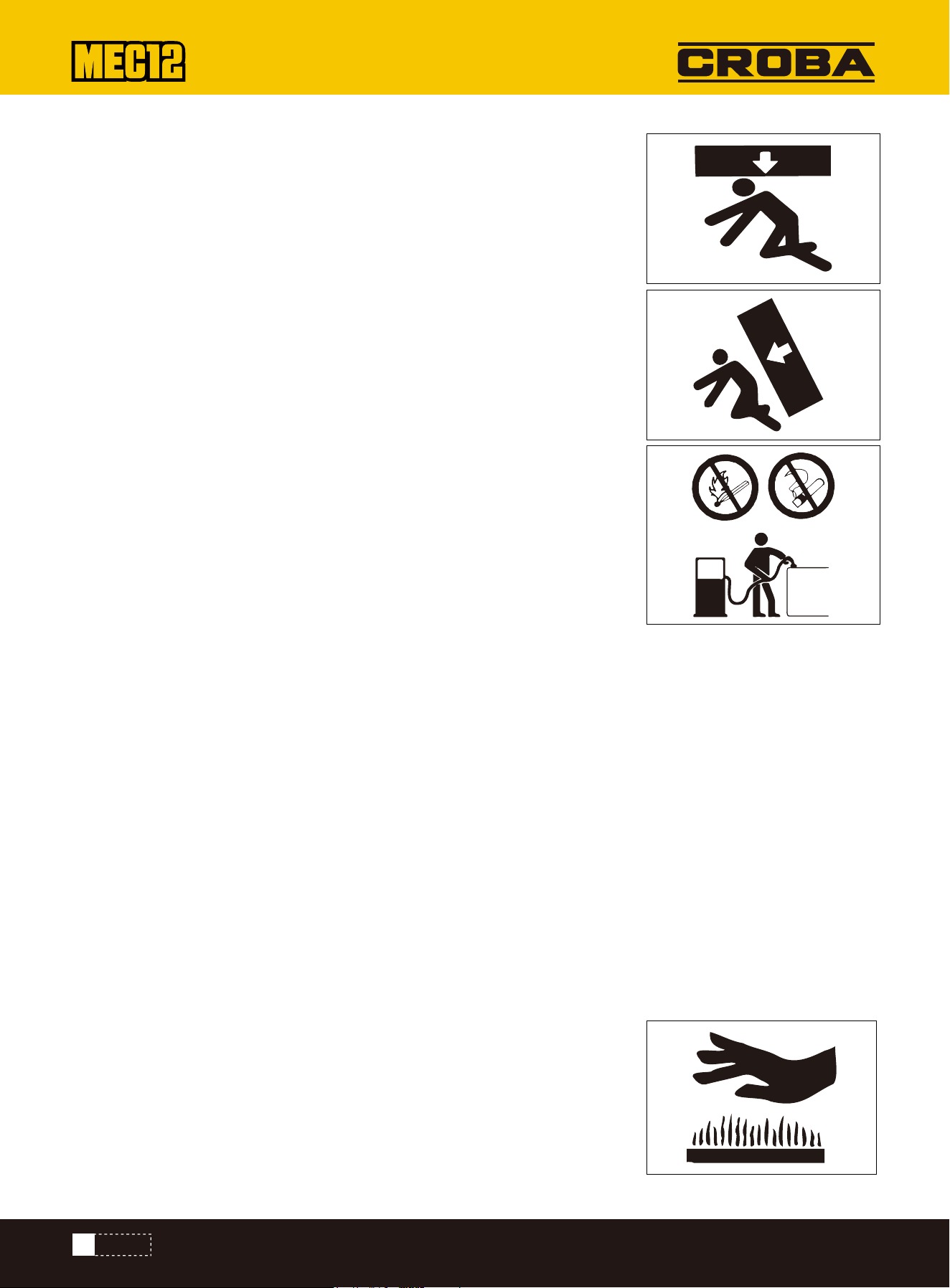
Secure Fixing of Machine and Possibly Falling Parts
Before performing any maintenance under the machine, lower all attachments
(work equipment) to the ground (or their lowest positions) and chock the tracks.
If you must work under a raised machine or attachment, always secure it with
blocking (wooden cribbing), jacks, or other firm supports. Do not go under the
machine or attachment until it is firmly supported.
This operation is especially important for the hydraulic cylinder operations.
Fixing of Working Device
During the repairs and replacements of bucket teeth or side teeth, to prevent the
accidental movement of machine, securely fix the working device.
Steady Placement of Opened Engine Hood and Cover
Before operations within the machine,please securely fix the engine hood or machine hood.Keep the engine hood or cover
closed under windy weather or while parking the machine on a slope.
Placement of Heavy Weights at Steady Place
If it's necessary to place temporarily heavy weights or attachments onto the ground during disassembling or installation,
please ensure to place them in a steady place. Keep the non-authorized personnel away from the place for storage of such
objects.
Precautions for Refueling
The smoking and open fire are prohibited during refueling and near the refueling point.
Do not disassemble the fuel tank cap or refuel while the engine is running or is not cooled down. Do not splash fuel to any
high temperature surface of machine.
Refuel the fuel tank in a well-ventilated place. Do not top up the fuel tank. Leave an expansion space for the fuel.
Any overflown fuel shall be wiped away immediately.
Tighten the fuel tank cap securely. If the fuel tank cap is missing, replace with original cap only. The use of non-authorized
fuel tank cap with poor ventilation willcause internal pressure in the fuel tank. Do not use fuel for any cleaning
purpose.Use correct fuel grade based on the season.
Handling of Hoses
The leakage of lubricating oil or fuel can result in fire accident.
Do not distort, bend, or impact any hose.
Do not use any distorted, bent, or cracked pipeline, metal pipe, or hose, otherwise it
will probably result in burst .Re-tighten any loose connector.
16
SAFETY

Absolution Caution during Handling of High Temperature and High Pressure Parts
Absolution Caution during Handling of High Temperature and High Pressure Parts
Please stop the engine and wait for the machine to cool down before maintenance.
The engine, exhaust pipe, radiator, hydraulic pipes, sliding parts, and many other
machine parts are really hot when the engine is just stopped.Touching such parts
can cause scalding.
The engine coolant,hydraulic oil, and other fluids are also under high temperature
and high pressue status.
Take cautions not to touch the hydraulic oilwhile loosening engine hood or connec-
tor.
Operating the machine under such condition willcause out-spray of hot oil to result
in scalding or injuries.
Do not disassemble the radiator cap or drainage plug when the coolant is hot. Stop the engine and wait for the engine and
coolant to cool down. Slowly loosen the radiator cap to relieve the internal pressure and then take it out.
Caution against Internal Oil Pressure
Take caution against internal oil pressure. After the stop of engine, the pressure in the hydraulic oil pipes can hold for a
long time.
Before the maintenance, thoroughly relieve the internal pressure.
The high pressure ofhydraulic oil can penetrate skin and eyes to cause serious injuries and blindness or even death.
Please bear in mind that the hydraulic oil permeating from orifices is nearly invisible to naked eyes. While checking for
leakage, wear goggles and thick gloves and protect the skin by paper boards or plywood to protect against the harms of
spraying hydraulic oil.
The hydraulic oilpenetrating into your skin must be cleared by a doctor familiar with such injuries with surgical method
within several hours.
Pressure Relief before Operations of Hydraulic System
Guard against Splashed Fragments during Use of Hammer
Disassembling cap or filter or disconnecting pipeline before the pressure relief of hydraulic system will probably result in
out-spray of hydraulic oil.
•Slowly loosen the bleeding plug to relieve the pressure of oil tank.
•While disassembling connector or plug or disconnecting hose, stand on one side, loosen slowly to gradually relieve inter-
nal pressure, and then take out.
•The engine oil or oil plug will probably spray out under the internal pressure of traveling motor oil tank. Please slowly
loosen the oil plug to relieve the internal pressure.
During the use of hammer, the pins and the metal fragments will probably fly out. It willprobably cause serious personal
harms.
•While hammering hard metal parts such as pins, bucket teeth, side teeth,and bearings, please wear protective articles
including goggles and gloves.
•While hammering pins and bucket teeth, ensure there is no person in surrounding area.
17
SAFETY
Guard against High Pressure Grease
No Disassembling of Track Pensioner
In the track pensioner, the grease is injected under high pressure.
If the tension is not adjusted by the following designated procedure, the grease
relief valve will probably fly out to cause injuries.
•Never loosen the grease pipe fittings.
•Slowly loosen the grease relief valve. Do not rotate it for>1 turn.
•Do not place your face, arms, legs, or body in front of the grease relief valve.
•If no grease flows out when the grease relief valve is loosened, the valve is
malfunctioned.
The track pensioner is installed with a high strength spring. If the track pensioner
is disassembled carelessly, the spring will spring out to cause serious injuries. Do
not disassemble the track pensioner.
Operations of Additional Devices
Take special cautions while handling the high pressure nitrogen stored in the tank.
The improper handling will probably result in explosion of nitrogen to cause serious
injuries. Please strictly abide by the following safety measures:
•Do not break up or disassemble.
•Keep away from open fire and fire source.
•Never drill hole, weld, or melt.
•Guard against physical vibration, such as hammering, rolling, and falling.
•Bleed the sealed air before handling the cylinder body
Disconnection of Battery Cables
Caution during Handling of Battery
Take special cautions while handling the high pressure nitrogen stored in the tank.
The improper handling will probably result in explosion of nitrogen to cause serious
injuries. Please strictly abide by the following safety measures
•The battery contains sulfur acid. The accidental touch will harm your eyes or skin.
•In event of accidental contact with eyes, immediately flush by clean water and quickly seek for medical treatment. In
event of accidental swallowing, drink a lot of water or milk and immediately seek for medical treatment.
•If the sulfur acid comes into contact with your skin or clothing,immediately flush by a lot of water.
•Wear goggles and gloves during handling of battery.
•The battery can generate inflammable hydrogen to probably cause explosion. Keep away from fire sources including open
fire, spark, and ignited cigarette.
•Use a flashlight to check the electrolyte level.
•Ensure to turn off the starter switch and stop the engine before checking or handling battery.
•Never touch the electrodes by any metal tool or object, in order to prevent short-circuit.
•The loose electrodes can generate electric spark. Ensure to tighten any loose electrode.
•Ensure that the battery cover is securely covered.
•If the battery is frozen, do not charge the battery or attempt the jumper start of engine, otherwise it willprobably cause
explosion. Before use, heat the frozen battery to 59°F.
•Do not use the battery when the electrolyte level is below the lower limit. Otherwise it will speed up the internal aging
and shorten thelife of battery. In addition, it can lead to burst (explosion).
18
SAFETY

Periodically Replaced Critical Safety Parts
•To guarantee the safe operation of machine for a longer time, add the oil and perform the inspection and maintenance
periodically. To promote the safety, periodically replace the critical safety parts, includng hoses and seat belts. To
understand more details, please refer to the section “Periodically Replaced Critical Safety Parts".
•Periodically replaced critical safety parts refers to the parts aged, worn, and functionally deteriorated after repeated
use. The performances of such parts will change along with time. These characteristics of such parts can cause serious
mechanical damages or personal harms and the remaining lives of such parts can't be judged by merely appearance
checking or operation hand-feel.
•Upon detection of any visible damage on the appearance, please replace the “periodically replaced critical safety parts",
even if the designated replacement period is not reached.
Jumper Start with Battery Charging Cable
Asking for Welding Repair
•To start the engine by battery charging cable, ensure to connect the cable correctly as per following procedure. The
incorrect connection of cable can cause discharging and battery explosion.
•Keep the "Malfunctioned machine" and "Rescue machine" away from mutual contact.
•Never touch the positive (+) and negative (-) electrodes of battery charging cable with each other or with the machine.
•During connection, firstly connect the positive electrode of battery charging cable to positive (+) terminal. During
disconnection, firstly disconnect the negative (-) terminal (grounding terminal) from the negative cable.
•Ensure to connect the cable clamps securely.
•Connect the last clamp of battery charging cable to a place as far as possible from the battery.
•To start the engine with battery charging cable,always wear goggles and gloves.
•Use the battery charging cable and clamps of dimensions suitable to the battery capacity. Never use damaged or corrod-
ed battery charging cable or clamps.
•Ensure that the battery capacity is same for the "Malfunctioned machine" and "Rescue machine".
The welding operations, if necessary, must be fulilled by competent personnel in a working site with complete equipment.
To prevent damaging any machine part by over-high current or electric spark, please abide by the following precautions.
•Disconnect the battery cables before electric welding.
•Do not apply 200V or higher voltage continuously.
•Connect the grounding point within 39.3 inchs reach from the welding area. Do not connect the grounding terminal near
the electronic control device/instrument or connector.
•Ensure there is no seal ring or bearng between welding area and grounding terminal.
•Do not connect the grounding terminal to the any place near the working device pin or hydraulic cylinder.
•Before the welding of machine body, disconnect the connector of electronic control device.
Waste Disposal
•Ensure to collect the drained oil of machine into a container. The improper treat-
ment of waste oil willpollute the environ- ment.
•While disposing harmful objects, including lubricating oil, fuel, coolant, solvent,
filter, and battery, please abide by the applicable laws and regulations.
•Do not fill the distilled water till the level is above the upper limit. Otherwise the electrolyte willleak out. The contact
with such electrolyte can harm your skin or corrode the machine parts.
•Clean the surrounding area of electrolyte level marking by a wet cloth and check the level. Do not clean by a dry cloth,
otherwise it can cause electrostatic accumulation and combustion or explosion.
19
SAFETY

SAFETY SIGNS
Disposal of Harmful Chemicals
Schematic diagram for safety signs:
The direct contact with harmful chemicals willcause serious harms.The harmful chemicals used in this machine
includeoils/greases, battery electrolyte, coolant, paint, and adhesive.Please dispose the harmfu chemicals carefully and
properly.
To guarantee the safety of operator and operating personnel in the working zone, please set up the following safety signs
(markings) at some portions of machine. Walk around the machine with this manual and observe the contents and place-
ment locations of these safety signs. Please review these signs and operation instructions contained in this manual
jointly with the machine driver.
• The safety signs shall be clean, clear, and easily legible.
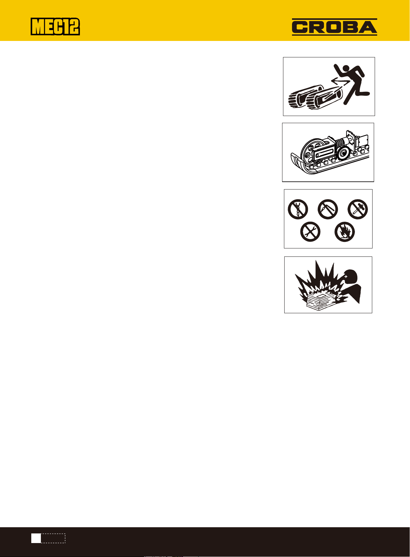
1.Precautions for adjusting caterpillar band tension: this sign is located on
both sides of caterpillar band beam.
The pressure in the oil cylinder of the belt tensioner is very high. Adjustment or
disassembly of the belt tensioner must be caried out in accordance with the
operator's manual.Incorrect operation may cause personal injury
3.Pay attention to warning labels such as fuel refueling precautions, load warn-
ings, movement/operation warnings, high-voltage line warnings, instructional
labels, and road speed/height warning signs.
These signs are located on the gasoline tank cover.
4.Sign away from turning area: This sign is located on the rear counterweight.
▲No one is allowed to stand within the rotating area of the mini-excavator.
▲Do not damage or remove the sign from the mini-excavator.
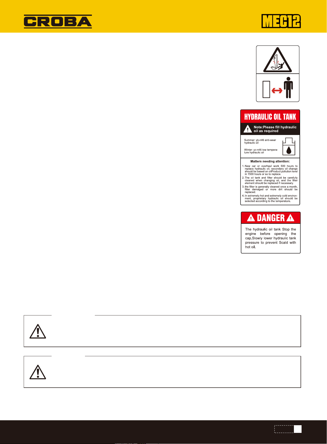
5.Fuel sign: This sign is located at the fuel tankfiller.
▲ Turn off the engine when filling fuel, and keep away from all open flames
when filling fuel.
▲Pay attention to view the precautions on the fuel label.
▲ Do not damage or remove the sign from the mini-excavator.
6.No one is allowed to stand in the operation area: this sign is located on both
sides of the working arm.
2.The grease filling sign is located on the key structure lubrication diagram:
20
SAFETY
SIGN ON PRECAUTIONS
It means that failure to observe the precautions will result in death or serious injury.
DANGEROUS
It means that failure to observe the precautions will result in death or serious injury.
WARNING
7.Stay away from the excavation area: this sign is located on both sides of the
bucket arm.
8.Hydraulic tank sign: this sign is located on the housing at the hydraulic oil
tank.
The precautions recorded in this manual and the label with A symbol posted on the mini-excavator are important items
that may lead to personal accidents.If thelabel with ▲ symbol is dirty or falls off, you must purchase it from the local
sales store and post it in the designated position.
The operation manual determines the matters needing special attention when using the mini-excavator as follows:
9.Danger sign for hydraulic oil tank: this sign is located on the tank cover plate.
21
SAFETY

It means there is a risk of injury if precautions are not followed.
NOTICE
It means that if the precautions are not observed, the mini-excavator will be damaged or cause failure.
PRECAUTION
It means other supplementary instructions that are helpful for use.
SUPPLEME
1. Battery maintenance sign:
2.Daily inspection:
3.Operation diagram for working device
Before using the mini-excavator, please read and understand the operation manual carefully to ensure safe operation. For
safe operation, please observe the above precautions and attach the supplement sign here to ensure safety first.
▲ please confirm whether there are abnormal faults (such as oil leakage, loose bolts and
nuts, loose electrical wiring, end wires, terminals, etc.) during the last use.
If there is a fault, please dispose it accordingly.
▲Please use the specified brand for fuel and grease.
▲Check whether the mini-excavator control mode is consistent with that indicated on thela-
bel. If there is a difference,replace the label before operating the mini-excavator to match the
mini-excavator control mode.
▲If the mini-excavator is not operated according to this procedure, it may cause casualties
(refer to the operation warning).
4.When pulling up the bucket, no one is allowed to enter under the bucket. When pulling up the
bucket, please do not touch the overhead wires or obstacles. In particular, death may be
caused by electric shock when touching wires, so please pay attention to this matter.
5.Take safety as the guideline, do not drive when you are drinking, taking medicine and in poor
health, otherwise it will cause accidents.
Note: when using this mini-excavator, please turn off the power in time to prevent battery loss from bringing unnecessary
trouble to you.
Children are not allowed near the device
Beware of acid corrosion
Refer to instructions
No fire
Wear protective glasses
Beware of explosive gases
Please read the instructions carefully before use
22
SAFETY
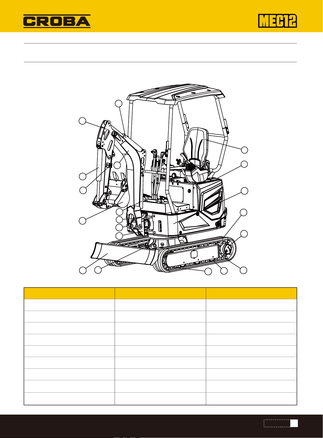
COMPONENT NAME
CONTROLS
Up frame
1. Seat
2. Engine hood
3. Hydraulic oil tank
4. Fuel tank
5. Track
6. Drive wheel
7. Track roller
8. Traveling motor
9. Bulldozer blade
10. Cylinder of blade
11.Guide the wheel
12. Bucket
13. Bucket cylinder
14. Arm
15. Arm cylinder
16. Boom
17. Boom cylinder
18. Swing joint
19. Swing cylinder
20. Hydraulic circuit
Working deviceChassis
23
CONTROLS
1
2
3
4
5
6
7
8
9
10
11
12
13
14
15
16
17
18
19
20
FUSE CASE, FUEL FILLING PORT, SEAT
During the refueling into the fuel tank, keep away from heat source and open fire and do not
smoke.
Refuel the fuel tank in a well-ventilated place. Stop the engine before refueling.
Any overflown fuel shall be wiped away immediately.
Do not top up the fuel tank. Leave an expansion space for the fuel.
Tighten the fuel tank cap securely.
WARNING
Fuse Case
This case is designed to protect the electric system against over-current.
Open
Fuel filling port
1.Insert the hood key and turn it counterclockwise to unlock the maintenance cover.
2.Lift the hood lock and lift the maintenance cover.
3.Locate the fuse box.
Close
1.Unlock the limit lever and close the maintenance cover.
2.Insert the hood key and turn it clockwise to lock the maintenance cover
Opening
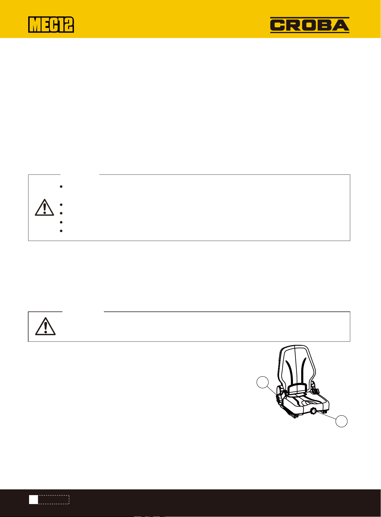
SEAT
1.Insert the hood key and turn it counterclockwise to unlock the maintenance cover.
2.Lift the hood lock and lift the maintenance cover.
3.Hold the fuel tank cap and turn it counterclockwise to unlock the fuel cap.
Closing Fasten the fue tank cap and turn it clockwise to lock the fuel cap.
A.Adjust the backrest angle
1.Stand up straight and sit back on the seat.
2.Adjust the backrest to the angle you want by rotating the handle
B.Front and back adjustment
1.Pull up the adjustment lever (2), slide the seat back and forth,and adjust it to the
position you want when operating the machine.
2.Loosen the adjustment handle (2) at the position you want to fix the seat.
Adjustment and Fixing of Seats (For high-end seats only)
WARNING
24
CONTROLS
1
2

NO.
1
2
3
4
5
6
7
8
Voltmeter
Hour meter
Telescopic swithch
Lamp switch
Speed switch
Key switch
Pilot lamp
Water-thermometer
The battery voltage should be about 12V, the voltage is too low or too high, it
may affect the normal operation of the excavator
Display working hours, the range is 0-9999.9h
Switch between chassis extension and retraction and push shovel
Control light switch
Switch between high and low speeds when moving
Control excavator start and stop
It lights up when the key is activated
Display the temperature of the water in the system
NOTEDESCRIPTION
Panel Name and Description
Precautions
This instrument is a water-proof instrument, featuring stable performance and high conciseness and elegance, and is an
intelligent instrument developed specially for small excavators. To guarantee the stable data and prolong the life of
instrument, please notice the following issues:
1.Do not disassemble the instrument without permission.
2.Never brutally hammer or knock the instrument.
3.Guard against external damages.
4.Keep the controlpanel clean. Any organic solvent or corrosive liquid, including gasoline, should be wiped off immediately
to prevent corrosion of the panel.
5.Should you have any question during use, please timely contact service personnel.
ELECTRICAL CONTROL PANEL
25
CONTROLS
1
2
3
4
5
6
7
8
www.mechmaxx.com
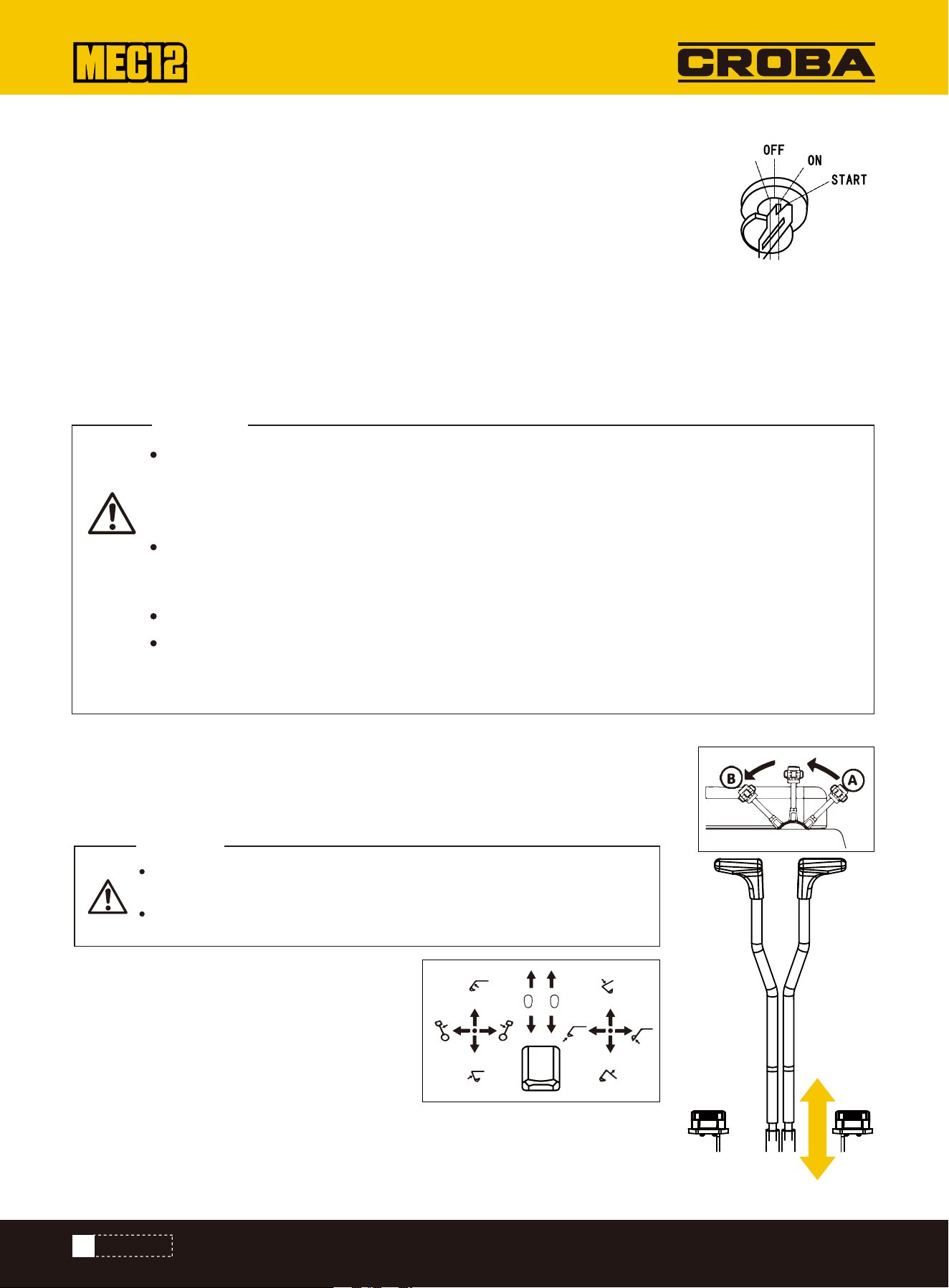
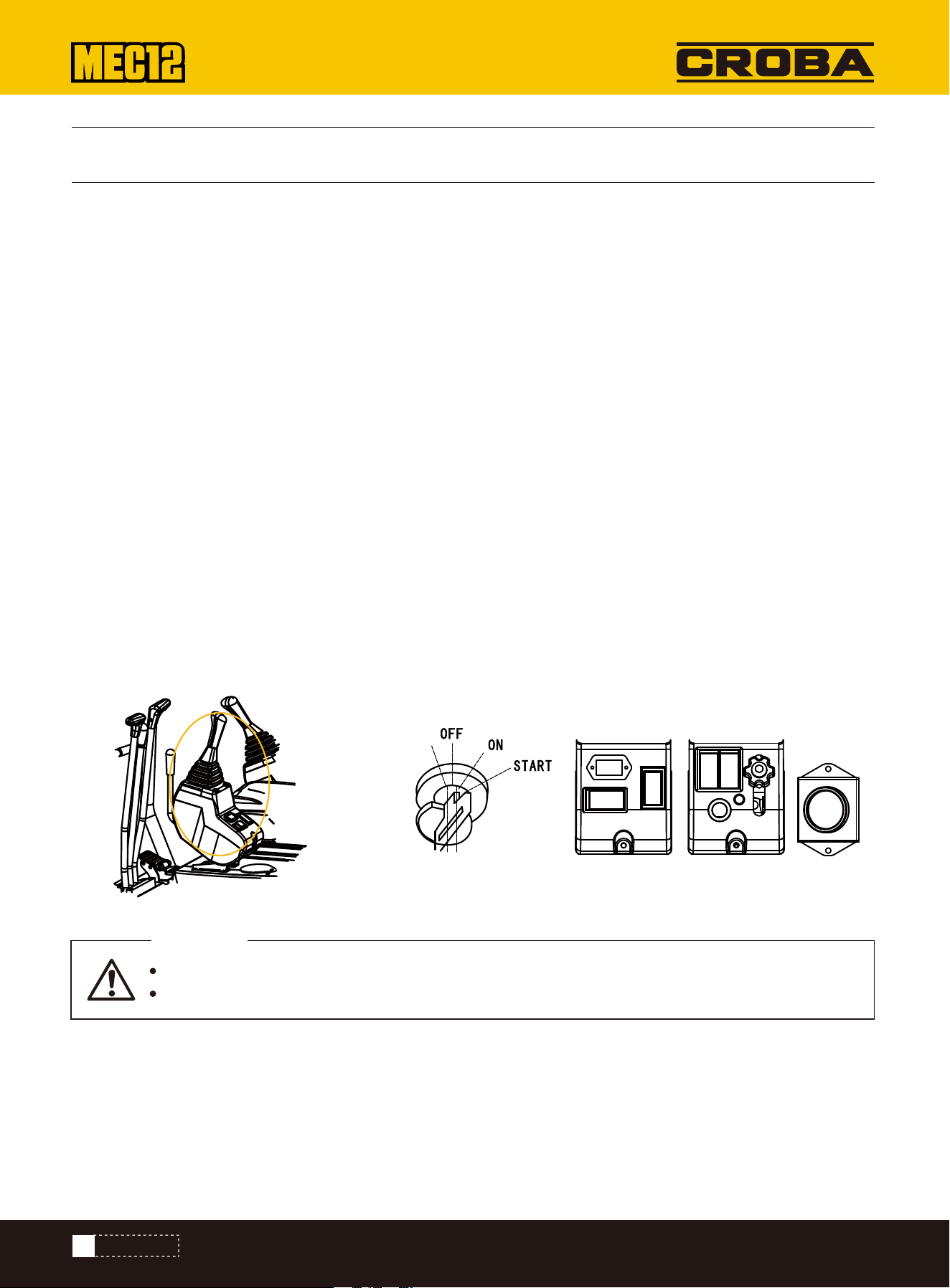
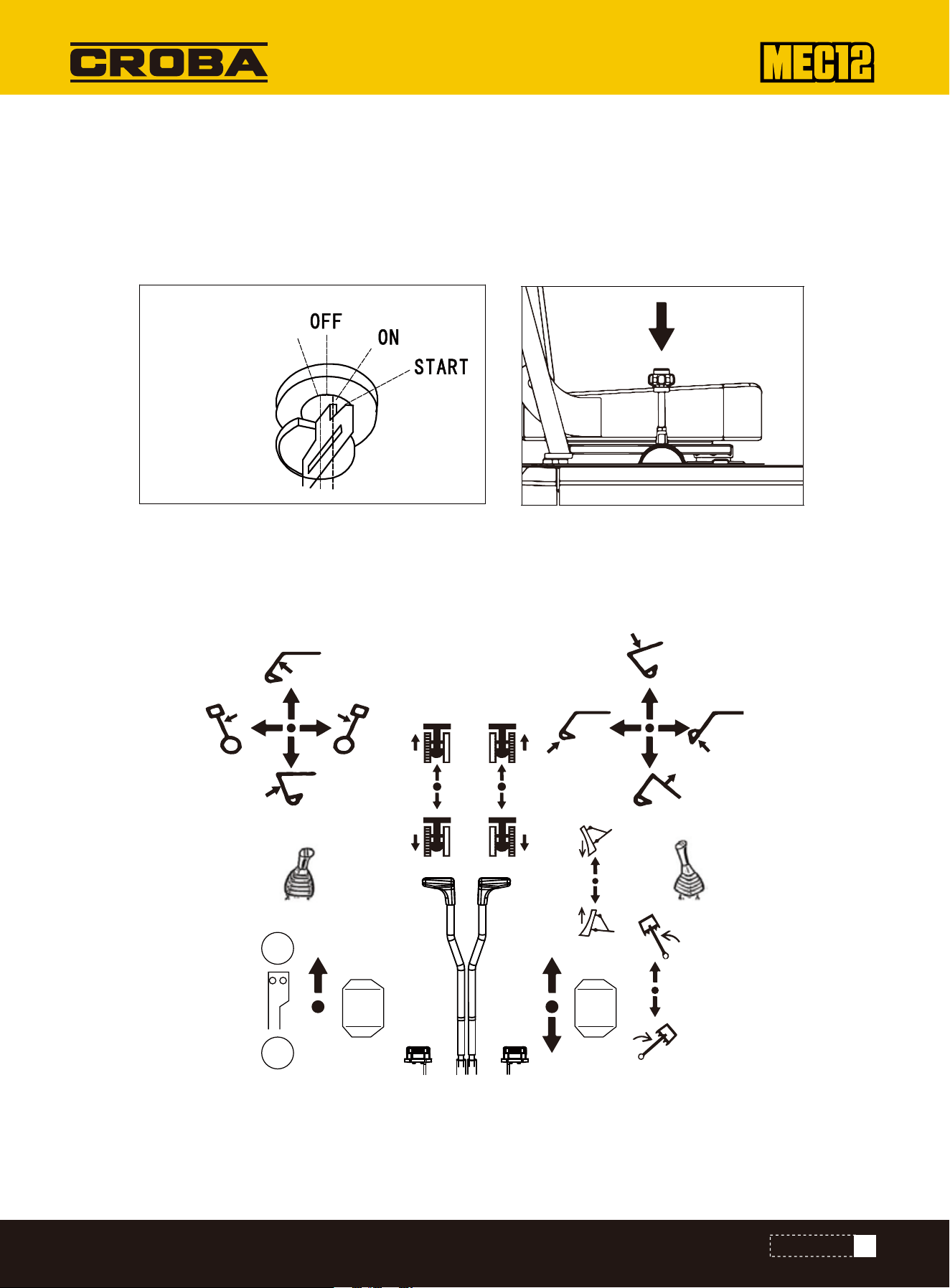
Starter Switch
Safety lock handle
Accelerator joystick
Important: Do not rotate the starter key from OFF to ON and then from ON to OFF
repeatedly within a short time, otherwise it will probably result in engine malfunction.
OFF……This position is used to stop the engine and insert and withdraw the starter key.
ON……Engine running position. All electric devices are functional at this position.
START……Engine running position. Upon release of key, the switch automatically returns to ON.
If the coolant temperature is too low, rotate counter-clockwise the key, hold for 10~15s, and then release before start.
Rotate the key to ON and then to START to start the engine.
This device is designed to lock the operations of bucket working device and machine slewing. When pushing the lever
forward, except for the walking lever, the other levers cannot work
Control Mode Bulldozing blade joystick
Use this joystick to operate the bulldozing blade
(A)…Lower the bulldozing blade.
(B)….Lift the bulldozing blade.
Used to control engine speed.(A)..low idle (B) ...Maximum speed Joysticks
Before standing up from the driver seat to adjust the operator’s seat, lower the working device to
the ground, lift up the safety lock handle to lock it, and stop the engine. When the safety lock
handle is lowered down (Unlocked), the accidental touch of any joystick will result in sudden
movement of machine and cause serious injuries or deaths.
Please note that, even if the safety lock handle is placed at locking position, the bulldozing
blade, boom, and auxiliary hydraulic controls can’t be locked. Do not touch such controls acci-
dentally.
While lifting up or lowering down the safety lock handle, take cautions not to touch any joystick
Before leaving the driver seat, lower the working device onto the ground, lift up the safety lock
handle to locking position, and stop the engine. Meanwhile, ensure to withdraw the key, close the
doors and hoods, and carry the key with you and then preserve it in a designated place.
WARNING
Before starting operations, please carefully check and confirm the
joystick mode to be used.
The descriptions in this manual use the ISO mode of machine.
WARNING
PREHEAT START
SWITCHES
JOYSTICKS AND PEDALS
26
CONTROLS
A
B
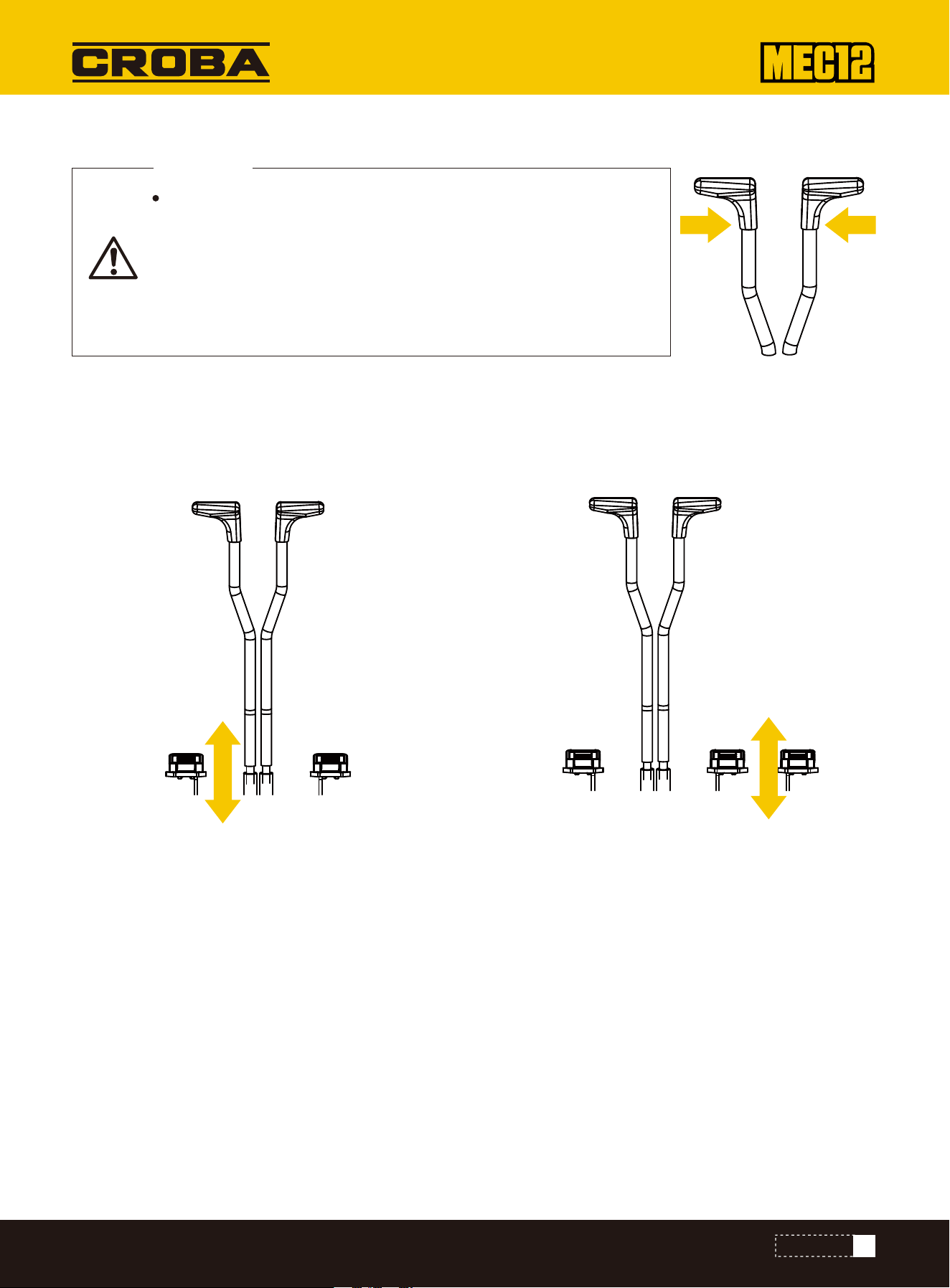
Traveling Joystick
Auxiliary hydraulic pedal
This right pedal is used for hammer operation.
Note: Make sure you have and correctly installed the
breaker device. Step on the pedal forward, the breaker will
start to work, release the pedal, and the breaker will stop.
Side swing control work device left and right skewing.
A.The working device is set off to the left.
B.The working device is deflection to the right.
Before operating the traveling joystick, ensure that the bulldozing
blade is in front of the driver seat. Please bear in mind that the oper-
ation direction of the traveling joystick with bulldozing blade behind
the driver seat is reverse to that with bulldozing blade in front of
driver seat.
Use these two levers to move forward or backward and change
direction.
WARNING
27
CONTROLS
A
B
A
B
ACCESSORY
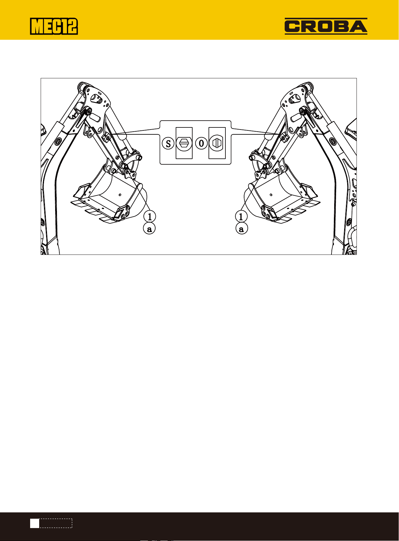
Connection of Hydraulic Circuits
Disconnecting hydraulic lines before relieving system pressure can cause a sudden release of hydraulic oil.
•After shutting off the engine, press all auxiliary hydraulic pedals and the secondary auxiliary switch several times to
release pressure from the auxiliary hydraulic circuit.
•Slowly loosen the bleed plug to relieve pressure from the hydraulic oil tank.
•When disconnecting hoses, stand to the side and loosen them gradually to allow pressure to escape before removal.
These lines carry the hydraulic oil required to operate breakers and other attachments.
To connect the attachment hydraulic pipeline, please operate as per following procedure:
1.Relieve the residual pressure from system and then close the shutoff valve.
2.Take out the plug.
3.Connect the attachment hydraulic pipes to ports (a). While installing a hydraulic breaking hammer, connect the oil inlet
port to port (a).
4.Open the shutoff valve. While installing a hydraulic breaking hammer,open the selector valve (1).
5.After connections, fully bleed the air from hydraulic pipes.
a.Start the engine and run at low idling speed under no-load condition for 10min.
b.During the running of engine at lowidling speed,operate the hydraulic auxiliary switch repeatedly (for approximately 10
times) to bleed the air from hydraulic pipes.
c.Stop the engine and wait for at least 5mintill the air bubbles overflow from the hydraulic oil in the oil tank. Important:If
applicable, follow the attachment manufacturer's procedure to bleed the air.
6.Check for presence of oil leakage.
(1)..Auxiliary hydraulic pipeline Shut-off valve
(S):Close
(0):Open
Auxiliary hydraulic pipeline (If installed).
28
CONTROLS

Disconnection of Hydraulic Circuits
1.Relieve the residual pressure from system and then close the shutoff valve.
2.Disconnect the pipelines from ports.
3.Install the plug.
Relieve residual pressure
After using the auxiliary hydraulic circuit, there is residual pressure in the circuit. This is called residual pressure. Before
disconnecting the pipeline, release the residual pressure.
29
CONTROLS
OPERATIONS
OPERATIONS
BEFORE START OF OPERATIONS
START AND STOP OF ENGINE
Getting on/off machine
•Do not jump on or off the machine. Do not attempt to get on or off a moving machine
•While getting on/off the footplates, hold the handrails to support your body weight and maintain three-point balance
posture (Hands and feet) for your body.
•Do not use safety lock handle or any joystick as handrail.
1.Adjust the seat to comfortable operating position.
2.Check and ensure that the safety lock handle is at locking position.
3.Check and ensure that all joysticks and pedals are in neutral position.
4.Insert the key into starter switch, rotate to ON position,and then check as below:
• All warning lamps turn on for 1s and the warning tone is issued for 2s. The instruments start working.
•Press the lamp switch and check and ensure that the boom lamp turn on.
If a lamp failto turn on or a warning lamp fails to sound, the lamp bulb or wire is Probably damaged.
Important:
Do not run the starter motor continuously for>15s. If the engine fails to start, wait for 60s and then attempt
to restart the engine.
Important:
If the engine stops because it runs out of fuel, add fuel, turn the key to the ON position for 60 seconds, and
then turn it to START. Running the starter motor too long before the fuel system is primed may cause starter motor
failure.
walk-around inspection
Before the first start of engine each day, fulfill one walk-around inspection.
Daily Routine Checking
Start of Engine
Before the first start of engine each day, fulfillone walk-around inspection. Refer to page from "Maintenance, daily routine
inspection".
Keep all personnel away from working zone.
Sound the horn to alert the personnel around machine.
WARNING
PREHEAT START
30
OPERATIONS OF MACHINE
Normal Start
Joystick Mode (ISO Mode)
1.Pull the accelerator joystick to neutral position.
2.Rotate the starter key to START position to start the engine.
3.After the engine is started, release the key. The key will automatically return to ON position.
4.Check and ensure that all warning lamps are already off.
5.Return the accelerator joystick.
•Before starting operations,please carefully check and confirm the joystick mode to be used.
•The descriptions in this manual use the ISO mode of machine.
A
B
PREHEAT START
31
OPERATIONS
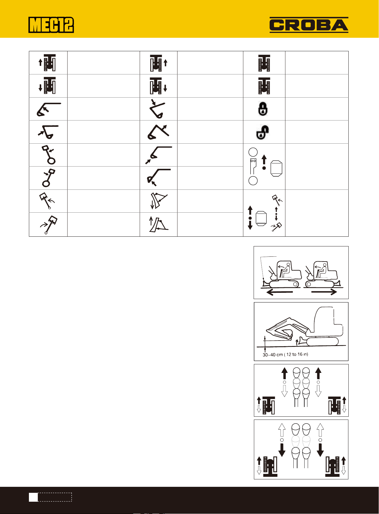
Drive leftward Drive rightward
Back up to right
Lower boom
Lift boom
Extending track
Retracting track
Safety lock locked
Safety lock
unlocked
Auxiliary oil
circuit
work/stop
The working
device swings
from side to side
Load bucket
Dump bucket
Back up to left
Extend arm
Retract arm
Slew leftward upper
frame
Slew rightward upper
frame
Swing leftward the
boom
Lower bulldozing
blade
Lift bulldozing
blade
Swing rightward the
boom
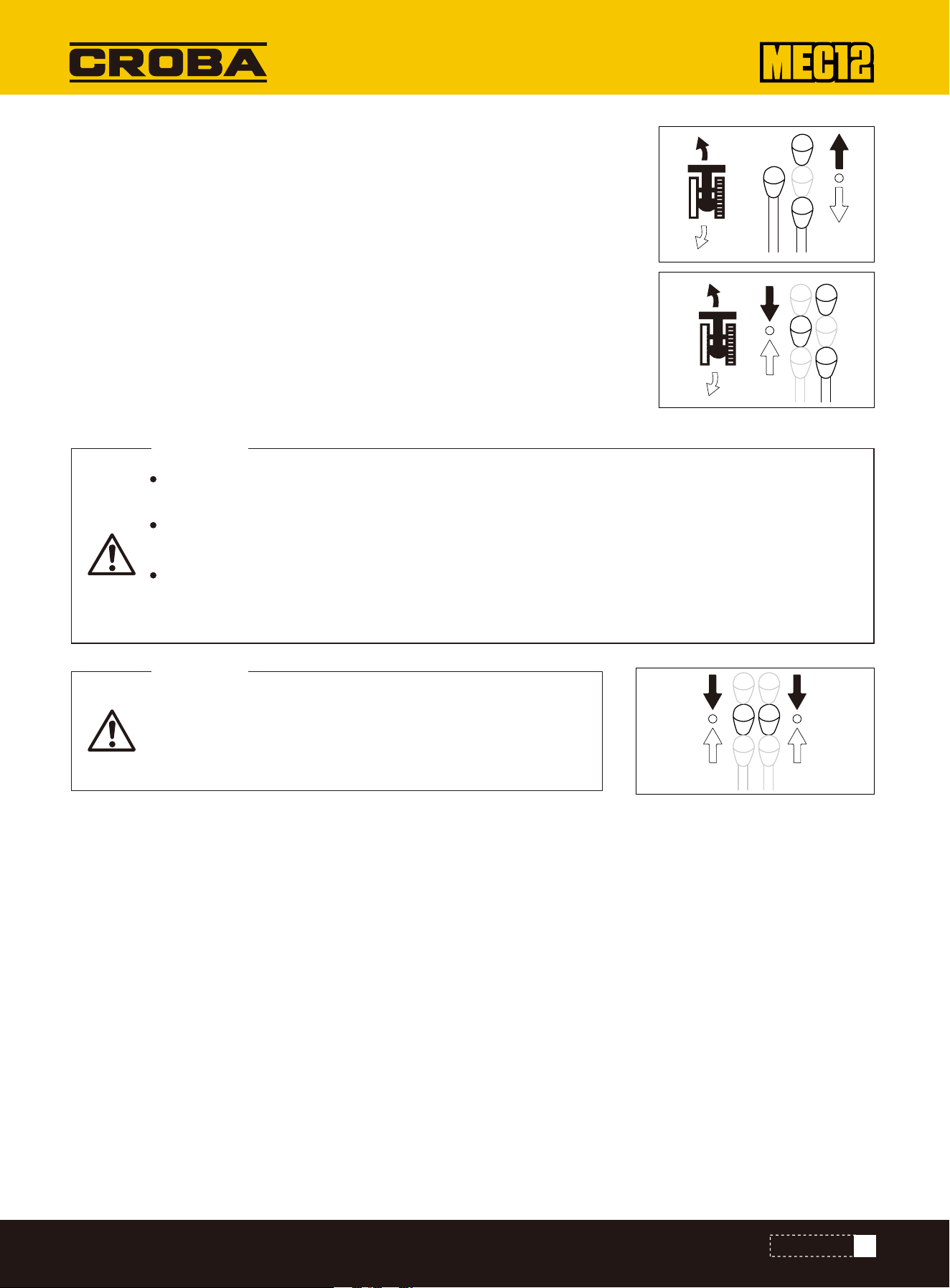
Operations of Traveling Joystick
•Do not allow any person to access the turning radius or path of machine.
•There are blind zones behind the machine.To reverse the machine, if neces-
sary,slew the cab to check the safety and ensure there is no person behind the
machine.
•Before operating the traveling joystick, ensure that the bulldozing blade is in front
of the driver seat. Please bear in mind that the operation direction of the traveling
joystick with bulldozing blade behind the driver seat is reverse to that with
bulldozing blade in front of driver seat.
•Remove all obstacles from the path of machine.Move the machine back and forth
1.Pull the accelerator joystick to increase the engine speed.
2.Fully lower the safety lock lever to release the lock.
3.Retract the bucket and lower to 12 to 16 in off the ground.
4.Lift the bulldozing blade.
5.Operate the traveling joystick as per following procedure. When the bulldozing
blade is in the front of cab:
To drive forward: Pull forward the joystick. To drive backward: Pullbackward the
joystick.
When the bulldozing blade is in the rear of cab: To drive forward: Pull backward the
joystick.
To drive backward:Pull forward the joystick. Pivot Steering
Turn left when parking:
To turn forward left: push the right traveling lever;
To turn back left: pull the right traveling lever.
Turn right when parking,same operating to operate the left travelinglever.
A
B
Bulldozing blade
32
OPERATIONS
Parking
Turning While Traveling
To turn left while moving forward: Release the left joystick to neutral.
To turn left while moving backward: Release the left joystick to neutral.
To turn right: Operate the right joystick in the same way.
Pivot Turns (Turning in Place)
To pivot left: Pull the left travel lever backward while pushing the right travel lever
forward.
To pivot right: Pull the right travel lever backward while pushing the left travel lever
forward.
Park the machine on a level, solid, and safe ground. Set the parking device. If it's necessary to
park the machine on a slope, block the track by wedges to prevent movement of machine.
When the safety lock handle is unlocked, the accidental touch of any joystick will result in
sudden movement of machine and cause serious injuries or deaths.
Please note that, even if the safety lock handle is placed at locking position, the bulldozing
blade, boom, and auxiliary hydraulic controls can’t be locked. Do not touch such controls acci-
dentally.
WARNING
Do not stop the machine hastily, unless in event of emergen-
cy. Stop the machine at the optimal timing whenever possi-
ble. Slowly place the left and right traveling levers to neutral
position. Stop the machine
CAUTION
33
OPERATIONS
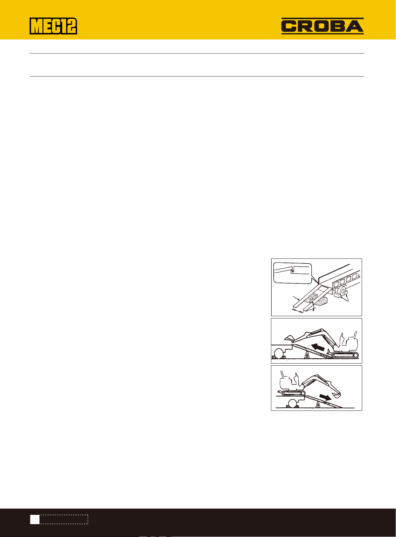
LOADING AND UNLOADING
TRANSPORTATION
The machine may roll over or fall during unloading. Always follow these safety precautions:
•Select a solid and level ground and keep a sufficient spacing from the road curb.
•Fix the ramps of sufficient strength and dimensions to the cargo body of truck. The inclination of the ramps shall not
exceed 15°. If the ramps deflect downward excessively, please support the ramps by supports or cushion blocks.
•Do not load or unload the machine by working device. Otherwise, it will probably result in rollover or falloff of machine.
•Keep the truck cargo body and the ramps clean without oil, sand, ice/snow, or other impurity, in order to prevent the side
slip of machine. Clean the tracks.
•Block the wheels of transport truck by wedges to prevent movement.
•While loading or unloading the machine, drive the machine slowly in 1st gear (low speed) as per the signals of the signal-
er.
•Do not change direction on ramps.
•Do not slew/swing on ramps. Otherwise the machine will probably roll over.
•Slewing/swinging the machine on the cargo body of truck will probably result in unstable legs of machine. Therefore,op-
erate slowly.
•If possible, lock the cab doors after loading. Otherwise the cab doors will probably open during the transport.
•Plug securely the tracks by wedges and then fix the machine to the truck cargo body securely by ropes or chains.
During the loading or unloading of machine, please ensure to use ramps or platform
and abide by following procedures.
1.Securely apply the parking device of transport truck and block the wheels by
wedges.
2.Place the ramps securely onto the truck cargo body. The inclination of the ramps
shall not exceed 15°.
3.Align the center of truck cargo body with the center of machine and align the
center of ramps with center of tracks.
4.Ensure that the bulldozing blade will not touch the ramps.
5.Lower the bucket working device as low as possible and take cautions not to
impact it with the transport truck.
6.Reduce engine speed.
7.According to the signaler's signals,drive the machine straightly up or down along
the ramps in 1st gear (low speed).
8.Load the machine to designated position of transport truck.
Stop block
15°or less
Distance
between
Ramp
Fix to suspension
parts
34
TRANSPORTATION

0VERVIEW
MAINTENANCE
ITEM
Engine oil
Engine oil filter
Engine gasoline pre-filter
Engine gasoline filter
Engine air filter
Traveling motor gear oil
Slewing motor gear oil
Hydraulic oil
Pilot filter
Return oil filter
Oil-intake filter
50 500 1000 1500 2000 2500 3000
NEW EXCAVATOR WORKING HOURS
SUBSEQUENT
REPLACE PERIOD
OIL GRADE
Ci4 15W-40500 hours
500 hours
500 hours
500 hours
500 hours
1000 hours
1000 hours
2000 hours
1000 hours
1000 hours
2000 hours
MAINTENANCE PARTS REPLACE PERIODIC CHART
Maintenance Overview
Maintenance Precautions
Keeping Machine Clean
To maintain the good status and long-term serviceability of the machine, please fulill the checking and maintenance
correctly and safely abide by the procedures recommended by this manual.
Based on the total operating time of the machine, the checking and maintenance items can be divided into several
groups: Every 10h (walk-around inspection and daily routine checking), every 50h, and every 250h. Pease refer to the
reading of hour meter to determine the checking and maintenance timing. The items for which the checking and mainte-
nance intervals can't be determined are listed in column “As necessary".
When the machine is operated in extremely severe environment (Dusty or high temperature environment), perform the
inspection and maintenance ahead of the periods specified by maintenance schedule.
NOTE:1.Mark the "√“ is need to replace;
2.When the excavator is equipped with hydraulic breaker, the replace period of hydraulic oil and hydraulic oil filter should
be reduced by half.
Do not fulfill any other checking or maintenance item not listed in this manual.
For the items not listed in this manual, please ask your sales or service dealer for help.
•Clean the machine before checking and maintenance. Keep the machine clean.
•Stop the engine before cleaning the machine. Cover the electric parts against water ingress. The water ingress into the
electric parts will probably result in short-circuit or malfunction. Do not clean the battery, electronic control units,
sensors, connector, or operating room by water or steam.
35
MAINTENANCE

SERVICE DATA
Position
Hydraulic oil tank Anti-wear hydraulic oil
Cooling system
Traveling reducer gear
Slewing motor gear
Slewing bearing
Working device
Arm
Every 50h
Every 50h
Daily or every 10h
As necessary
Coolant (Water +
coolant) **
SAE: J814C or J1034
Gearbox API: GL-4 SAE 90
Lithium-base grease
EP-2 MLGI 2#
First 250h *
Afterwards every
1000h
Every 2000h ***
Every 1000h
Type depending on temperature
4°F 14°F 32°F 50°F 68°F 86°F 104°F
Replacement
period
Type
Precautions for Refueling
•If the fuelfiller port is installed with a filter screen,do not remove the filter screen during refueling.
•Please ensure to tighten the fuel tank cap after refueling.
•The refueled volume shall not exceed the designated fuel volume.
•Regardless of the specified periods, replace the oil when the oil is too dirty or already deteriorated.
•Never mix the oils of different trademarks while adding fuel/oil. To replace with fuel/oil of other trademark, please
replace completely
No Cleaning of Engine Parts by Fuel
It's prohibited to clean engine parts by fuel. Use non-inflammable detergent.
Guard against Ingress of Dusts
The installation and disassembling of parts shallbe operated in a dust-free place. Clean the working area and clean the
parts to guard against ingress of dusts.
Cleaning of Mounting Surfaces
Keep clean the contact surface of parts during the installation and disassembling. If the sealing grooves of the contact
surfaces are damaged,please contact your sales or service dealer for repairs or breakup.
Lubricant
ISO VG32
ISO VG46
ISO VG68
50% coolantmixture
30% coolant mixture
36
MAINTENANCE

System
Hydraulic system
Engine lubrication
system
Air filter system Air filter
Fuel system
Ventilator
Engine oil filter
Fuel filter
Filter cartridge
Filter cartridge
Primary (Outer) filter
element
Secondary (Inner)
filter element
Replac e after first 50 hours, then every
250 hours
0 20
500
1000
1500
2000
40 60 80 100
Every 1,000h or 6 cleaning cycles
(Whichever comes first)
At replacement of primary filter
element
Every 250h
Every 1000h
Filter replacement period
Breaking hammer operating ratio (%)
Part name Replacement periodItem
Item
1
st
time
2
nd
time
Periodic (1200)600
25
100
200
--
--
Filter elementHydraulic oil
PERIODICAL REPLACEMENT OF HYDRAULIC OIL
LIST OF WEARING PARTS
With installed hydraulic breaking hammer, the hydraulic oil deteriorates faster than the common digging operations.En-
sure to replace the hydraulic oil and oil return filter element.
•The failure to replace timely will result in damage of machine and breaking hammer hydraulic system. To prolong the
lives of hydraulic devices, please timely replace the hydraulic oil and oil return filter element as per the table below.
•During the replacement of hydraulic oil, clean the oil suction filter screen. Replacement period (Hour).
Periodically replace the wearing parts, including filters and filter elements, as per the table below.
For example, assuming a 100% operating ratio of
the hydraulic breaker, refer to ‘Hydraulic Breaking
Hammer’ for details.
Hydraulic device replacement period
(): For the use of common anti-wear
Replacement period (Hour)
37
MAINTENANCE

Vehicle body
Fuel system
Heater
Fuel pipes
Hydraulic pipe (Pump outlet)
Hydraulic pipe (Pump oil suction port)
Hydraulic pipe (Slewing motor)
Hydraulic pipe (Traveling motor)
Hydraulic pipe (Boom cylinder pipeline)
Hydraulic pipe (Bucket arm cylinder pipeline)
Hydraulic pipe (Bucket cylinder pipeline)
Hydraulic pipe (Swing cylinder)
Hydraulic pipe (Bulldozing blade cylinder)
Hydraulic pipe (Span cylinder)
Hydraulic pipe (Pilot valve)
Hydraulic pipe (Auxiliary pipeline)
Seat Belt
Anti skid plate
Packing on fuel tank cover
Heater hoses
Cooling system
Main
machine
Hydraulic
system
Working
device
Rubber hoses
Replacement period
Every 2 years
Every 3 years
Periodically replaced critical safety part
List of Critical Safety Parts
CRITICAL SAFETY PARTS
To operate the machine safely, please fulfill the periodical checking and maintenance. The following critical safety parts
shallbe replaced periodically to improve safety. These parts can cause serious injuries or fire accident if they are
damaged.
The materials of the above-mentioned critical safety parts will deteriorate along with time to cause wear or deteriorated
performance. It's difficult to determine the deterioration extent during periodical checking. Therefore, such parts shall be
replaced with new ones to guarantee stable performance, even if such parts are stillworking well. Please note that,
regardless of the replacement schedule, any part with wear symptom must be replaced immediately. Upon detection of
any deformed or cracked pipe clamp, immediately replace it together with hose. Please consult with your sales or service
dealer for the replacement of safety parts.
Except the critical safety parts, check and tighten the hydraulic pipes and when necessary replace.
During the replacement of hydraulic pipes, replace the Oring and seal ring as well.
Check the fuel and hydraulic pipes as per the schedule specified by the following table. Refer to "Maintenance".
38
MAINTENANCE

Checking type
Daily routine checking
Monthly checking
Yearly checking
Leakage of hydraulic or fuel pipe connector
Leakage of hydraulic or fuel pipe connector
Damage (Cracking, wear, and tear) of hydraulic or fuel pipe
Leakage of hydraulic or fuel pipe connector
Aging, distortion, and damage (Cracking, wear, and tear) of hydraulic or fuel pipe
and/or status of hose in contact with other machine parts
Checking item
Opening of engine hood and machine hood for checking
walk-around inspection of machine
1.Check for presence of branches, leaves, oil, and other inflammable around the engine and battery.
2.Check for presence of lubricating oil and coolant leakages around the engine.
3.Check hydraulic oil pipes, hydraulic devices, hoses, and connectors for oilleakage.
1.Check lamps for presence of dusts and damages and check lamp bulbs for burnout.
2.Check hydraulic accessories and hoses for damage.
3.Check bucket, bucket teeth, and side teeth for wear, damage, and looseness.
4.Check hook, anti-slip stop block, and hook seat on bucket for presence of damage. (Optional)
5.Check handrails, footplates, and anti-slip surfaces for damage and check for any loose bolt.
6.Check tracks and track shoes for presence of slip, check track carrier rollers, idling device,and sprocket for presence
of damage and wear, and check for loose bolt.
7.Check traveling motor for oil leakage.
8.Check shelter and guard plates for damage and check for loose nuts and bolts.
9.Check exterior and interior rear view mirrors for contamination and damage and when necessary adjust.
10.Check labels for presence of dusts and damage.
Checking in Driver Seat
1.Check seat and seat belt for presence of dust and damage.
2.Check driver seat for presence of dust, oil dirt, and other inflammable.
3.Check monitor, electric devices, and switches for oil dirt, dust, and damage.
39
MAINTENANCE

TROUBLESHOOTING
NO BATTERY POWER
Remedy procedure
Cable to Start Engine.
•If the steam overflows from the engine, do not open the engine hood or machine hood. The steam or hot water will proba-
bly spray out to cause scalding.
•Do not disassemble the radiator cap or drainage plug when the coolant is hot. Stop the engine,wait for the engine and
radiator to cool down, and then slowly loosen the radiator cap to relieve the internal pressure.
•Please stop the engine and wait for the machine to cool down before maintenance. The following symptoms indicate
overheating
•Engine water temperature should be<221°F.
•Steam came out of the engine room.
The following symptoms indicate no battery power.
•No rotation of starter motor or start failure of engine.
•Low volume of horn.
Start the engine by the booster battery on other machine (booster machine) and jumper cable.
•To start the engine by jumper cable, ensure to connect the cable by correct procedure. The improper use of jumper cable
will result in battery explosion or unexpected machine motions.
•The booster machine and the machine with depleted battery are prohibited for mutual contact.
•The positive (+) and negative (-) clamps of the jumper cable are prohibited for mutual contact.
•During connection, firstly connect the jumper cable to positive (+) terminal.During disconnection, firstly disconnect the
cable from negative (-) terminal.
• Connect the last clamp of jumper cable to a point as far as possible from the battery
Important: The jumper cable and clamps in use shall be suitable to the battery capacity. Do not use any damaged or
corroded jumper cable or clamp.
Important: Ensure the same capacity for the battery on the rescue machine and the battery on malfunctioned machine.
Important: Ensure to connect the cable clamps securely.
Connection of Jumper Cable
mportant: Place the starter keys of both rescue machine and malfunc-
tioned machine to OFF.
1.Connect a clamp of jumper cable (R) to the positive (+) pole of malfunc-
tioned machine.
2.Connect the other jumper cable clamp (R) to the booster (+).
3.Connect the jumper cable camp (B) to the charger (-).
·Always wear goggles while using jumper
4.Connect the other clamp of jumper cable (B) to the engine support of
the malfunctioned machine. Connect the clamp to a point as far as possi-
ble from the battery.
4
1
2
3
R
B
To engine block
Battery of malfunctioned
machine
Battery of rescue
machine
40
TROUBLESHOOTING
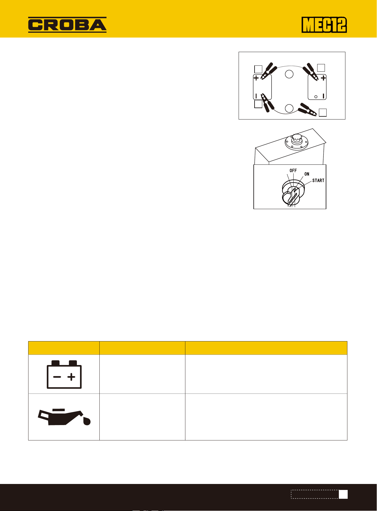
Warning lamp
Charging warning
lamp
There is a problem with charging.
If the light continues to flash after maintenance,
there may be a problem with the charger. If you need
help, please consult your sales or service agent.
The engine lubrication system is internally
malfunctioned. Check the engine oil level.
If this lamp flashes when the oil level is normal or
still flashes after adding of oil, please consult with
our service team. “Checking and adding of engine oil”.
Engine oil pressure
indicator lamp
Lamp name Cause and solution
RESTART AFTER REFUELING
FLASHING OF WARNING LAMPS
After Start of Engine
1.Check and ensure that the wire clamps are already connected securely to
various terminals.
2.Start the engine of rescue machine and run it at high speed.
3.Start the engine of the malfunctioned machine.
Disconnection of Jumper Cable
Air exhausting from Fuel System
Recharging
After the successful start of the engine of malfunctioned machine,disconnect
the jumper cable in reverse sequence of the connection procedure.
1.Disconnect the clamp of jumper cable (B) from the engine support of
malfunctioned machine.
2.Disconnect the other jumper cable (B) from the charger (-).
3.Disconnect the jumper cable (R) clamp from the charger (+).
4.Disconnect the jumper cable clamp (R) from the uncharged machine (+).
Important: Do not rotate the engine by starter motor to get ready the fuel system. This willprobably cause overheating of
starter motor to damage coil, pinion, and/or ring gear.
Important: If the engine stops due to shortage of fuel, please add fuel,rotate the key to ON for 60s, and then rotate it to
START position. Running the starter motor for a long time before the supply of sufficient fuel will cause start failure of
starter.
1.Add fuel.
2.Turn the starter key to the ON position and hold it for about 60 seconds.
Note: The air content in the fuel system willcause start failure or other problems of engine. Ensure to exhaust when the
fuel tank is empty or the fuel system contains air.
If a warning tone is heard or a warning lamp starts to flash during operations,park the machine in a safe place and take
the following remedy measures.
Please ask your sales or service dealer to recharge the depleted battery.
PREHEAT START
4
1
2
3
R
B
To engine block
Battery of malfunctioned
machine
Battery of rescue
machine
41
TROUBLESHOOTING

PARAMETERS
BASIC PARAMETERS
MEC12
Model
Engine
No.Of Cylinders
Stroke
Bore
Rated speed
Displacement
Engine Output
Travel Speed - High
Travel Speed - Low
Maximum Traction Force - Low Speed
Ground Clearance
Ground Pressure
Gradeability - Maximum
Operating Weight
Type
Max.Discharge Flow
Swing Speed
Tail Swing Radius
Boom Length
Arm length
Bucket Digging Force
Arm Digging Force
Fuel Tank
Cooling System
Engine Oil
Hydraulic Oil Tank
Kubota D722
3
2.68in
2.64in
2500rpm
43.88in³
13.7hp
2.24 mile/h
1.12 mile/h
2923lbf
15.9in
5.1psi
Maximum 30 degrees
2646lb
Load Sensing Hydraulics with Variable Displacement Piston Pump
4.65 gpm
8rpm
48.1in
52in
35in
1960lbf
875lbf
2.4gal
1.1gal
0.7gal
3.2gal
42
PARAMETERS
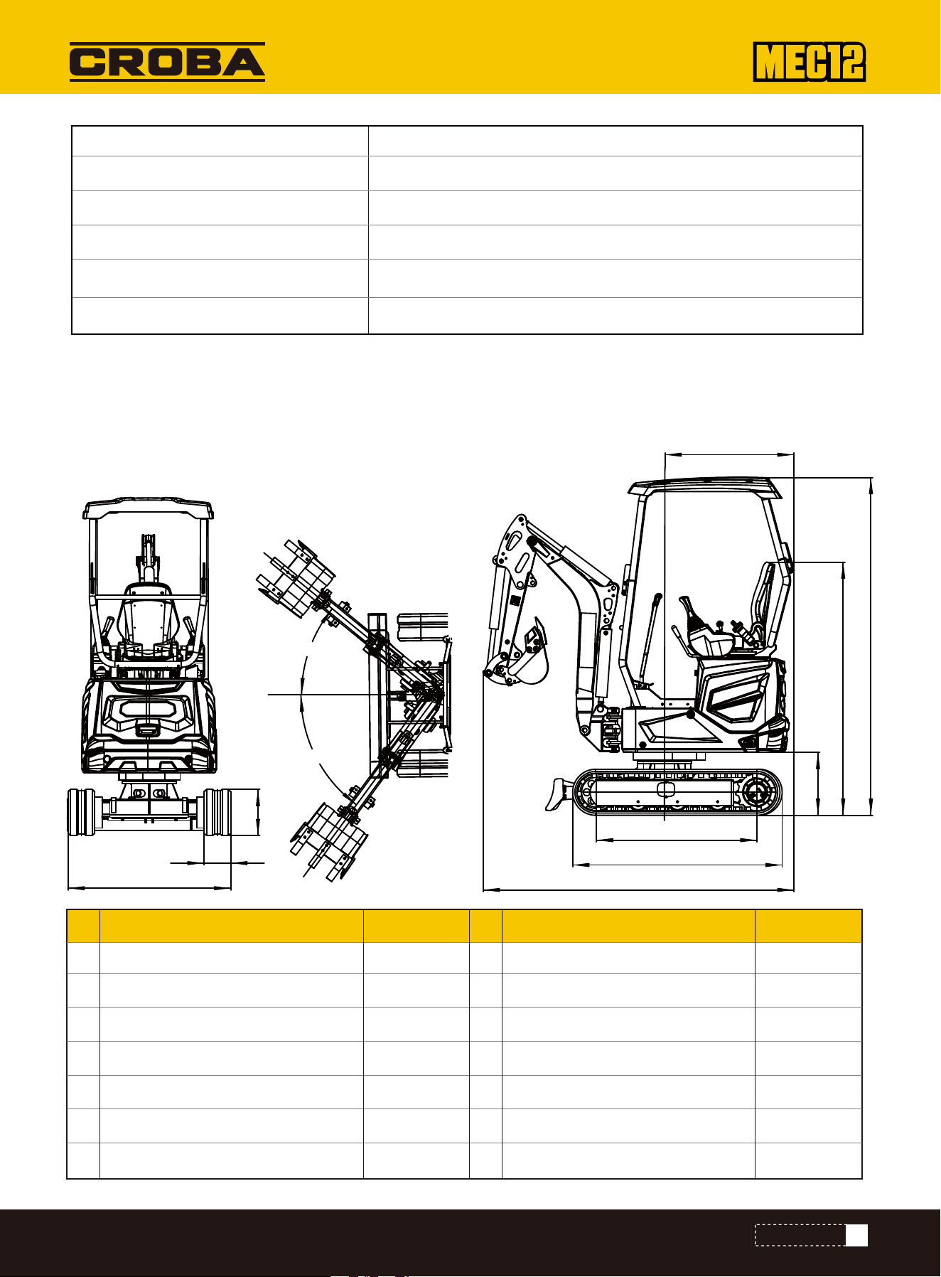
OVERALL DIMENSIONS OF MACHINE
All ratings of the machine are obtained when the machine is operating on a solid horizontal support surface. If the work-
ing environment conditions of the machine differ from the above-mentioned reference conditions (Such as the operations
on uneven ground and slope), the operator shall take these conditions into consideration.
Overall dimensions
a
b
c
d
e
f
g
h
i
j
m
n
Wheel track Transport length
Ground clearance of seat
Overall height
Boom slewing - right
Boom slewing – left
Overall length of crawler
Ground clearance of platform
Tail slewing radius of platform
Chassis width
Track width
Track height
42.5
55.5
16.7
34.2
42.7
7
12.6
92.4/114.8
67.1
89.5
40°
53°
Unit: inch Overall dimensions Unit: inch
System Capacity
Bucket Capacity
Bucket Width
Package Method
Warranty for Machine
Warranty for Engine
4.8gal
0.7 ft³
15 in
Wood Case
1 Year
2-Year or 2,000-Hour Warranty, Whichever Comes First.
43
PARAMETERS
e
f
g
m
n
a
b
h
c
i
j
d
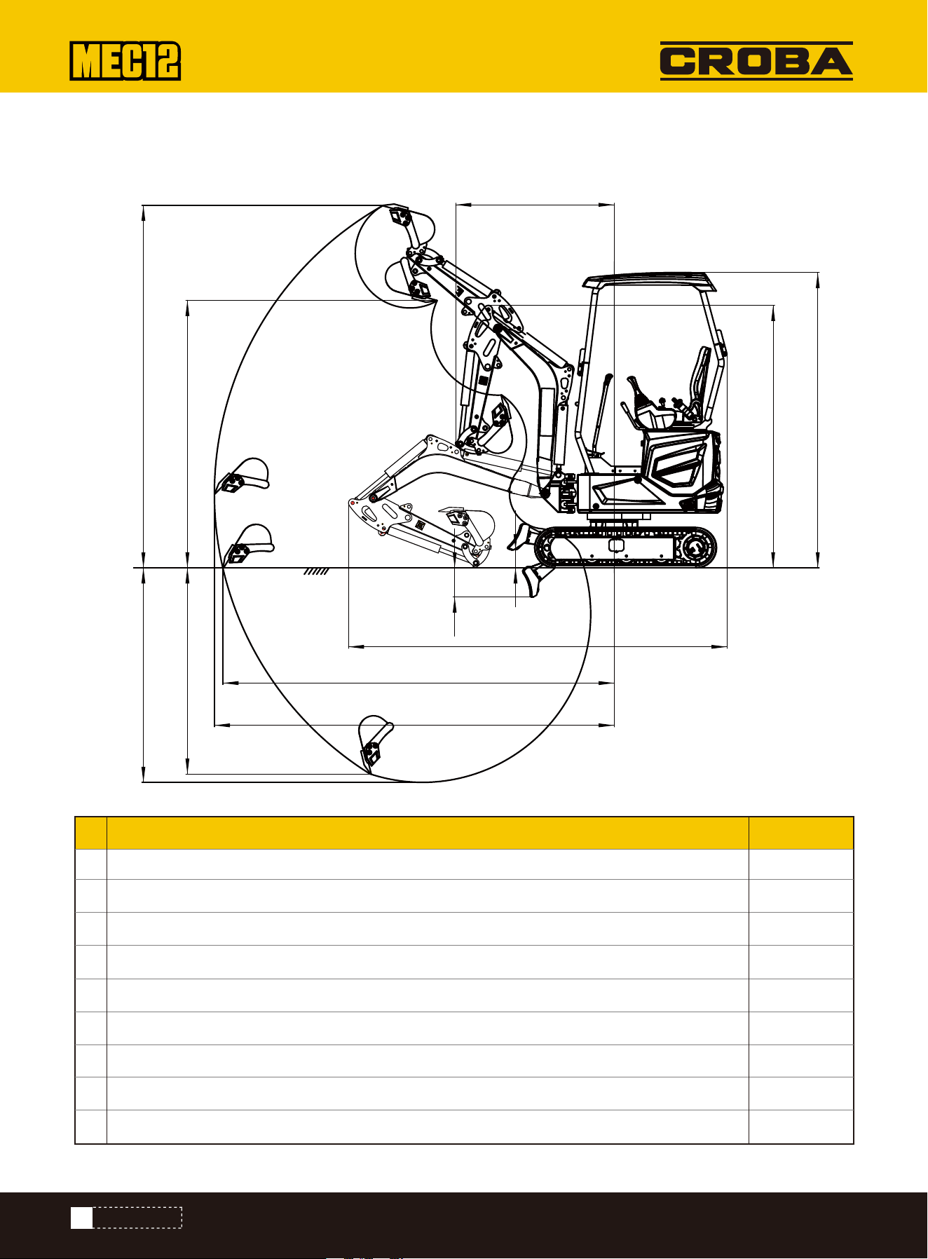
OPERATING RANGE
Working range
L
J
H
F
G
I
K
M
N
Ground maximum digging radius
Maximum digging radius
Maximum digging depth
Maximum digging height
Maximum Dump height
Maximum vertical digging depth
Minimum slewing radius
Maximum lifting height of bulldozing blade
Maximum digging depth of bulldozing blade
118.7
121.2
65
111.2
81.1
62.6
48.1
5.5
8.9
Unit: inch
44
PARAMETERS
M
N
A
L
J
I
G
H F
K
C2
C1

ACCESSORIES
PRECAUTIONS FOR OPERATIONS
PERIODICAL REPLACEMENT OF HYDRAULIC OIL
•Start the engine and run at 75% of maximum speed
•Perform the crushing operation by placing the hammer head perpendicular to the working face.
•During the crushing operations,appropriately aim the hammer head at the object to be crushed and avoid the air impact.
•Do not pry by hammer head or pry during breaking.
•Do not move the hammer head during crushing.
•Do not impact one same surface continuously for>30s.
•Do not crush when the cylinder is fully extended or retracted(at travel end). Reserve at least 50mm travel.
•Do not crush when the bucket arm is perpendicular to the ground.
•Do not crush any object to be impacted by the gravity drop of breaking hammer.
•Do not use the breaking hammer to move any object or rock to be crushed.
•Slew the machine occasionally to cool down the engine.
•In event of abnormal vibration of hydraulic pipes, the nitrogen in the accumulator is probably leaking. Please check as
soon as possible.
With installed hydraulic breaking hammer, the hydraulic oil deteriorates faster than the normal operations. Ensure to
replace the hydraulic oil and oilreturn filter element.
•The failure to replace timely will result in damage of machine and breaking hammer hydraulic system. To prolong the life
of hydraulic system, ensure to replace the hydraulic oil and oil return filter element after the hours listed in table below.
•During the replacement of hydraulic oil, clean the oilsuction filter screen. Replacement period(Hour)
Item
1
st
time
2
nd
time
Periodic (1200)600
25
100
200
--
--
Filter elementHydraulic oil
By taking the breaking hammer operating ratio of 100%
for instance.
0 20
500
1000
1500
2000
40 60 80 100
Filter replacement period
Breaking hammer operating ratio (%)
Hydraulic device replacement period
(): For the use of common anti-wear
Replacement period (Hour)
45
ACCESSORIES
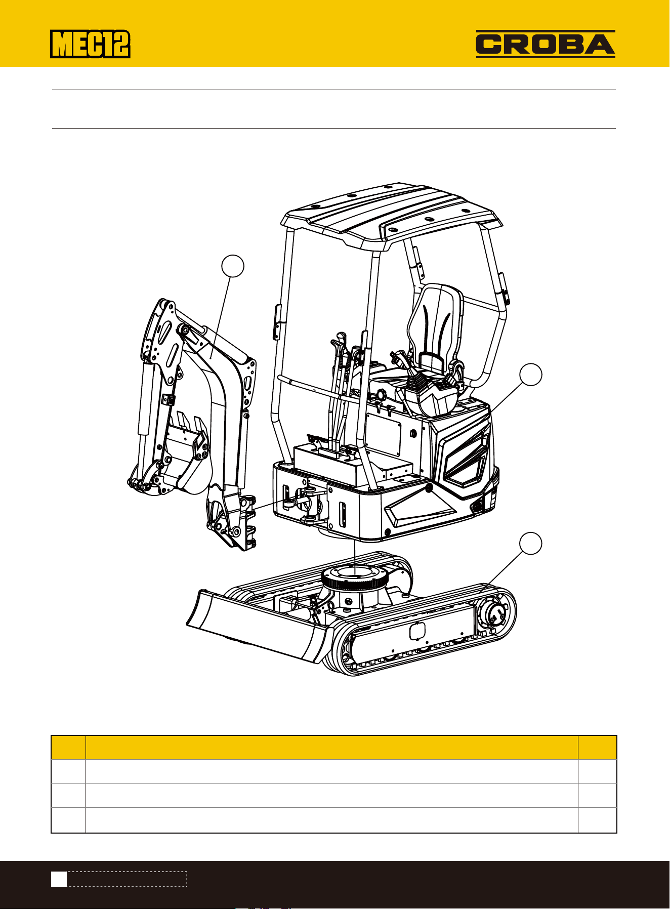
EXPLODED VIEW & PARTS LIST
1
1
1
No. DESCRIPTION QTY
1
2
3
Front operating device
Upper frame assembly
Lower frame assembly (retractable)
Exploded View -- Front Operation, Upper Frame, Lower Frame Assembly
Parts List -- Front Operation, Upper Frame, Lower Frame Assembly
46
EXPLODED VIEW&PARTS LIST
1
2
3
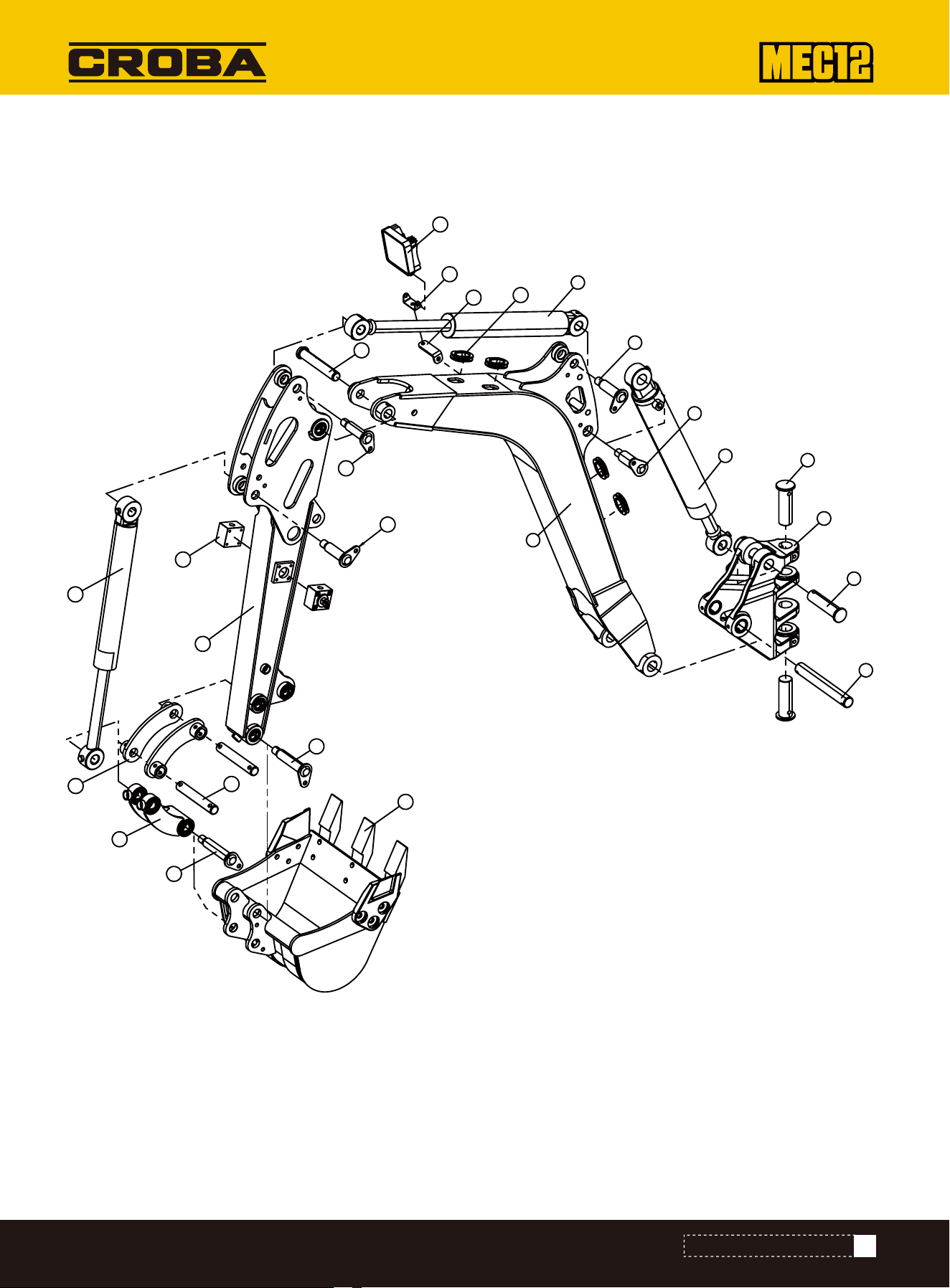
Exploded View -- Front Operating Device Assembly-1
4
1
2
3
6
9
8
10
7
5
13
12
11
14
16
19
20
21
22
24
25
23
18
17
15
47
EXPLODED VIEW&PARTS LIST

1
1
1
1
1
1
1
1
1
1
1
1
No. DESCRIPTION No. DESCRIPTION QTY
1
2
1
1
1
1
1
1
1
1
1
1
1
QTY
1
2
3
4
5
6
7
8
9
10
11
12
13
14
15
16
17
18
19
20
21
22
23
24
25
Swing head
The pin shaft 11
The pin shaft 12
The pin shaft 16
Main arm
Move the arm cylinder
The pin shaft 5
The pin shaft 3
The bucket pole cylinder
Rubber protection circle
Light bracket
Light installation seat
light
The pin shaft 15a
The pin shaft 3
Dipper
The pin shaft 3
globe valve
Dig bucket cylinder
rocking bar
connecting rod
The pin shaft 9
The pin shaft 7
The pin shaft 7
Bucket
Parts List -- Front Operating Device Assembly-1
48
EXPLODED VIEW&PARTS LIST
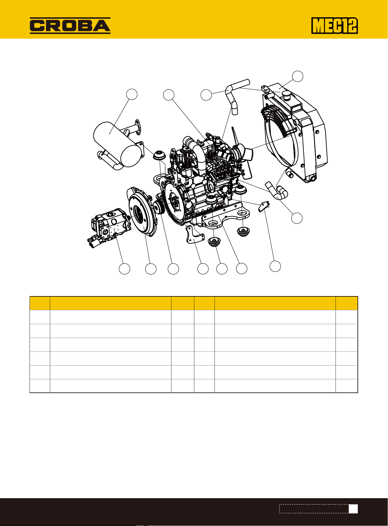
No. DESCRIPTION No. DESCRIPTION QTY
1
1
1
1
2
8
1
1
1
1
1
1
QTY
1
2
3
4
5
6
7
8
9
10
11
12
Engine
Dear pump
Courier shell
Flywheel disc
Engine leg welding
Engine shock absorber
Backing board
Silencer fixed board
Silence
Radiator
Water absorption tube
Wet return
Upper frame assembly (Part of the component explosion details) - 2
Exploded View -- Engine Assembly
Parts List -- Engine Assembly
49
EXPLODED VIEW&PARTS LIST
1
2
3
4
5
6
7
8
9
10
11
12
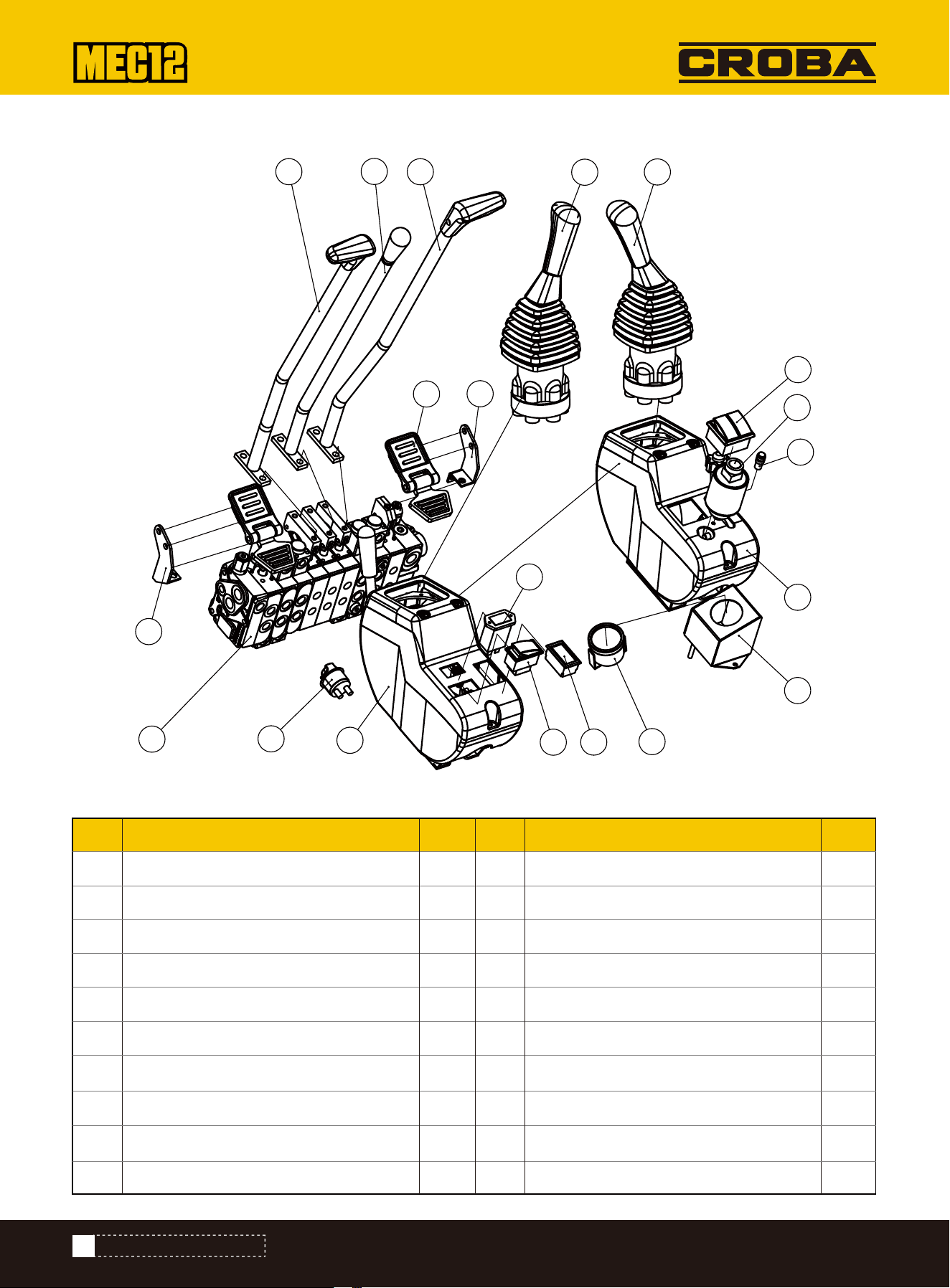
Exploded View -- Front Hood Valve Operating Device
No. DESCRIPTION No. DESCRIPTION QTY
1
1
1
1
1
1
1
1
1
1
1
1
1
1
1
1
1
1
1
1
QTY
1
2
3
4
5
6
7
8
9
10
11
12
13
14
15
16
17
18
19
20
Master valve
Left footrest mounting plate
Right footrest mounting plate
Foot pedal
Left travel lever
Push blade control lever
Right travel lever
Main power switch
Left armrest compartment
Right armrest compartment
Left pilot handle
Right pilot handle
Voltmeter
Hour meter
Telescopic switch
Lamp switch & Speed switch
Start switch
Pilot lamp
Temperature gauge mounting plate
Water-thermometer
Parts List -- -Front Hood Valve Operating Device Assembly
50
EXPLODED VIEW&PARTS LIST
1
2
3
4
5
6
7
8
9
10
11
12
13
14
15
16
17
18
19
20
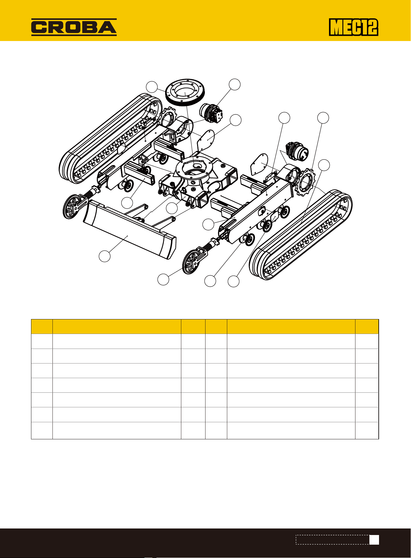
No. DESCRIPTION No. DESCRIPTION QTY
1
1
1
1
2
6
2
QTY
1
2
3
4
5
6
7
8
9
10
11
12
13
2
2
2
2
2
1
Get off the rack
Left beam
Right beam
Dozer blade
Steerable wheel
Thrust wheel
Driving wheel
Walking motor
Rubber belt track
Detent plate cover
Reaction member
Motor head guard plate
Rotary support
Exploded View -- Get off parts-3
Parts List -- Retractable Lower Frame Assembly-1
51
EXPLODED VIEW&PARTS LIST
1
2
3
4
5
6
7
8
9
10
11
12
13
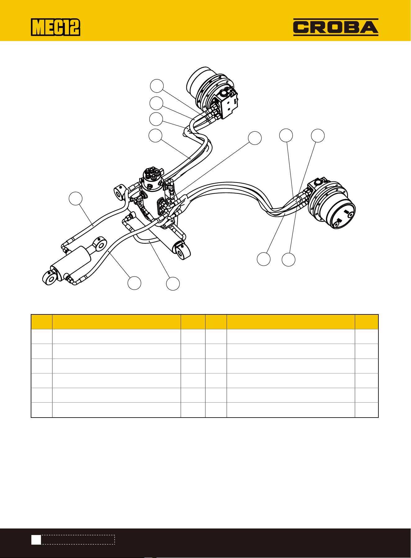
No. DESCRIPTION No. DESCRIPTION QTY
1
1
1
1
1
1
QTY
1
2
3
4
5
6
7
8
9
10
11
12
1
1
1
1
1
1
Hydraulic hose
Hydraulic hose
Hydraulic hose
Hydraulic hose
Hydraulic hose
Hydraulic hose
Hydraulic hose
Hydraulic hose
Hydraulic hose
Hydraulic hose
Hydraulic hose
Hydraulic hose
Exploded View -- Hydraulic Pipeline Assembly
Parts List -- Hydraulic Pipeline Assembly
52
EXPLODED VIEW&PARTS LIST
1
2
3
4
5
6
7
8
9
10
11
12
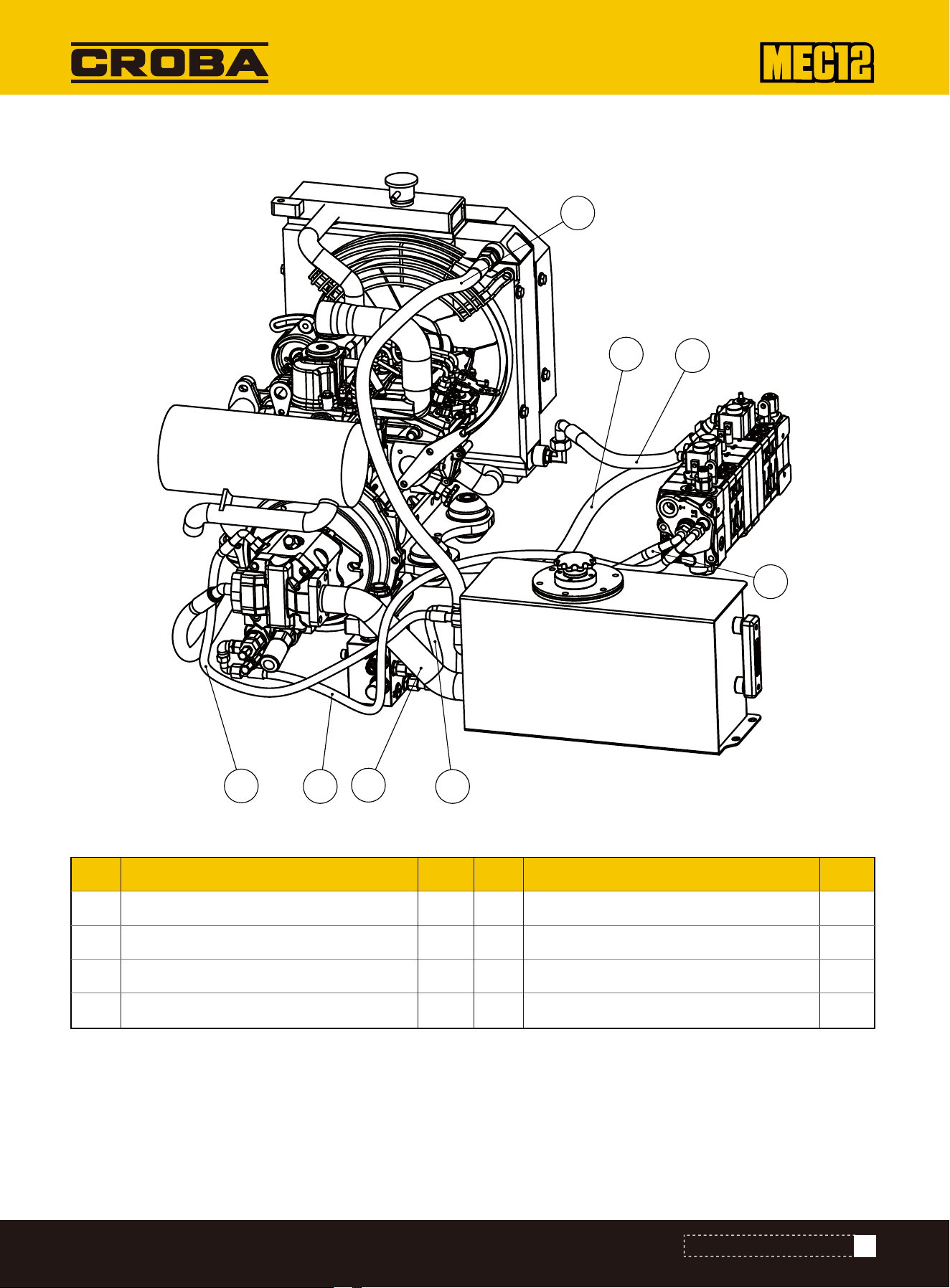
Exploded View -- Hydraulic Pipeline Assembly (Valve Part of the Front Hood)-1
No. DESCRIPTION No. DESCRIPTION QTY
1
1
1
1
QTY
1
2
3
4
5
6
7
8
1
1
1
1
Hydraulic hose
Hydraulic hose
Hydraulic hose
Hydraulic hose
Hydraulic hose
Hydraulic hose
Hydraulic hose
Hydraulic hose
Parts List -- Hydraulic Pipeline Assembly (Valve Part of the Front Hood)-1
53
EXPLODED VIEW&PARTS LIST
1
2
3
4
5
6
7
8

No. DESCRIPTION No. DESCRIPTION QTY
1
1
1
1
1
1
1
1
1
1
1
1
1
1
1
1
1
QTY
1
2
3
4
5
6
7
8
9
10
11
12
13
14
15
16
17
Hydraulic hose
Hydraulic hose
Hydraulic hose
Hydraulic hose
Hydraulic hose
Hydraulic hose
Hydraulic hose
Hydraulic hose
Hydraulic hose
Hydraulic hose
Hydraulic hose
Hydraulic hose
Hydraulic hose
Hydraulic hose
Hydraulic hose
Hydraulic hose
Hydraulic hose
Exploded View -- Hydraulic Pipeline Assembly (Valve Part of the Front Hood)-2
Parts List -- Hydraulic Pipeline Assembly (Valve Part of the Front Hood)-1
54
EXPLODED VIEW&PARTS LIST
1
2
3
4
5
6
7
8
9
10
11
12
13
14
15
16
17

QUESTION REASON ANSWER
The engine cannot start, the starter does not
respond, and the instrument does not light up.
The engine cannot start. The starter can drive
the engine to rotate.
The engine can start but is difficult to start
The engine starts but runs erratically
Engine overheating
The engine keeps emitting black smoke
1.The battery is completely
empty
2.cable link broken
1.The battery is low
2.Cables are loose
3.flooded cylinder
1.Fuel level low
2.There is water in the fuel
system
3.The fuel pipe is cracked
4.Fuel pump pressure is low
5.The engine oil model is wrong
6.Engine overheating
1.Fuel system air intake
2.Engine speed regulator is
loose
3.The fuel filter is clogged
4.The air filter is clogged
1.Cooling system blocked
2.Engine overload
3.The cooling system cover falls
off
4.The fan belt is too loose
1.The air filter is clogged
2.The amount of fuel injected by
the fuel injection nozzle is too
large.
1.Replace the battery or
charge it
2.Check the disconnection
and repair it
Recharge or replace
battery
Tighten cable glands
Remove the spark plug.
Start the machine with
the key switch to remove
excess fuel. Check the
spark plug.
1.Add fuel to the
appropriate location
2.Drain the water
3.Replace the fuel pipe
4.Replace and repair
5.Change the
temperature and add
appropriate type of
engine oil.
6.Check the cooling
system
1.Replace the fuel line
2.Adjust the engine
speed regulator
3.Replace filter element
4.Replace the air filter
1.Clean and cool the tin
tube
2.Adjust the engine speed
to match the hydraulic
system
3.Fasten the cover
4.Adjust the belt to the
appropriate tension
1.Replace the air filter
element
2.Replace the fuel injector
55
EXPLODED VIEW&PARTS LIST

The engine emits white or blue smoke
1.Fuel quality is too poor
2.Too much oil is added
1.Replaced fuel
2.Add the appropriate
position according to the
engine oil dipstick
QUESTION REASON ANSWER
The whole machine has no action
The whole machine moves slowly
Unable to dig
The machine shuts down when doing
movements
Hydraulic oil temperature is too high
Tracks fall off
1.Hydraulic pump damaged
2.The safety valve is damaged
3.The hydraulic oil model does
not match the temperature.
4.The safety lock is not opened
1.Hydraulic oil level is too low
2.Hydraulic oil viscosity is too
high
3.Control valve is damaged
4.cylinder internal leakage
5.The hydraulic pump is
damaged
1.Hydraulic oil level is too low
2.Hydraulic oil temperature is
overheated
3.Hydraulic oil temperature is
too low
4.The pressure safety valve is
damaged
5.Hydraulic pump damaged
1.Fuel oil line sucks air
2.Engine hydraulic pump power
does not match
3.Hydraulic oil filter is clogged
1.Hydraulic oil level is too low
2.Hydraulic filter element is
clogged
3.The cooling system is blocked
1.The track is too loose
1.Repair or replace
2.Replace the safety valve
3.Replace the
appropriate hydraulic oil
4.Open the safety lock
1.Add hydraulic oil to the
appropriate oil level gauge
2.Heating the hydraulic
oil while the engine is
idling
3.Repair or replace
4.Inspect and repair
5.Repair or Replace
1.Add hydraulic oil to level
2.Check the cooling
system
3.Machine idling to preheat
hydraulic oil temperature
4.Replace the safety valve
5.Replace the hydraulic
pump
1.Check the fuel line or
replace it
2.Increase engine speed
3.Replace the hydraulic
oil filter element
1.Add hydraulic oil
2.Replace the hydraulic
filter element
3.Clean the cooling
system
1.Tighten the track
56
EXPLODED VIEW&PARTS LIST