
Operator’s Manual
www.mechmaxx.com
WARRANTY


GENERAL INFORMATION
This manual is intended to ensure the machine is used as designed by the manufacturer, with safety as a top priority.
Anyone operating the machine or working nearby must read and understand this manual thoroughly. It is written for
trained operators with the necessary knowledge and basic skills required for handling this type of machinery.
Before installing or operating the machine, familiarize yourself with the content of this manual. Review the machine’s
features and safety components carefully before use. Always keep this manual with the machine for easy reference.
The instructions, descriptions, and technical specifications in this manual reflect the most current information available
at the time of printing. However, as the manufacturer continuously improves and updates the machine, changes may be
made to its features or safety-related components without prior notice.
The firewood processor is designed specifically for preparing firewood from pruned wood or logs. It must not be used to
process treated wood, such as construction waste. Materials containing sand, nails, or other foreign objects can cause
serious damage to the machine.
The maximum allowable log diameter is 15 inches (38 cm)—this limit must not be exceeded. When estimating the diam-
eter, consider that irregular shapes, branches, and burrs can increase the effective size of the log, potentially preventing
proper feeding into the machine.
Do not attempt to split logs longer than 24 inches (60 cm).
PURPOSE OF THIS MANUAL
PURPOSE OF USE
Always keep this manual in the immediate vicinity of the machine.
1
www.mechmaxx.com
GENERAL INFORMATION

TABLE OF CONTENTS
TABLE OF CONTENTS
GENERAL SAFETY INSTRUCTIONS
2
4
SPECIFICATIONS
3
ASSEMBLY
6
SAFETY INSTRUCTIONS
4
SAFETY SIGNS
4
CONTENTS SUPPLIED
6
INSTALLATION THE MACHINE
6
CONNECT the TERMINAL to the BATTERY.
22
22
ENGINE
22
ADD THE HYDRAULIC OIL.
24
LUBRICATION
24
JAMMING OF THE CUTTING BLADE
32
JAMMING OF THE WOOD ON THE SPLITTING KNIFE
32
Hydraulic Hose List
34
MAIN EXPLODED DRAWING
35
FEED CONVEYOR EXPLODED DRAWING
37
Main Parts List
36
Feed Conveyor Parts List 37
WOOD FEEDING, CUTTING AND SPLITTING
24
USING THE DISCHARGE CONVEYOR
25
AFTER USE
25
MACHINE CONTROLS AND FUNCTIONS
26
PERFORMING A TEST RUN ON THE MACHINE
27
ADJUSTING THE LOG LENGTH
28
HEIGHT ADJUSTMENT OF THE SPLITTING KNIFE
28
REPLACING THE SPLITTING KNIFE 28
CUTTING BLADE AND DRIVE END 29
CHANGING THE HYDRAULIC OIL 29
CONVEYOR MAINTENANCE 30
WASHING AND CLEANING 31
STORAGE 31
MAINTENANCE TABLE 31
ADJUSTING THE TIGHTNESS AND ALIGNMENT
OF THE DISCHARGE CONVEYOR BELT
28
SETTING UP BEFORE USE
26
OPERATING
28
MAINTENANCE
32
FAILURES AND REMEDIAL MEASURES
33
HYDRAULICS DIAGRAM
35
EXPLODED VIEW
2
www.mechmaxx.com
TABLE OF CONTENTS

3
www.mechmaxx.com
SPECIFICATIONS
SPECIFICATIONS
Engine
Displacement
Weight
Height/width/length in transport position
Input conveyor
Output conveyor
Saw bar/chain
Max log diameter
Max/min log length
Honda GX390
389 cc
1246 lbs
Transport position 251/136/262 (cm)
41"X10"
126"x10"
18"
15"
Log max 24"; min 6-1/2"
ZONSEN GB460
459 cc
Model HLS20
4
www.mechmaxx.com
SAFETY SIGNS
The rating plate on your machine may show symbols. These represent important information about the product or instruc-
tions on its use.
•This device is designed to be operated by only one operator. The danger zone is 10 m from the machine.
•Persons under 18 years of age may not operate the machine.
•The operator must ensure that use of the device does not cause danger to others and that there are no unauthorised
persons in the danger zone.
•The machine may not be operated while under the influence of alcohol or other drugs, or when tired.
•The machine may not be operated unless the operator has familiarised themselves with this instruction manual.
•The machine has been designed solely for making firewood.
•The machine must be placed in the transport position whenever it is moved. When transporting the machine on a public
road, it must be equipped with additional lights.
•The operator is not permitted to modify the structure or operation of the machine, or to remove protective equipment.
•The operator must wear ear protectors, sufficiently tight-fitting work clothing and gloves, protective goggles and safety
footwear.
•Before starting up the machine, the operator must ensure that the machine and its guards are intact.
•Before starting up the firewood processor, the operator must ensure that all the control and safety devices are function-
al.
•When cleaning the machine or carrying out any maintenance, it must be disconnected from its power source.
•Note! Do not leave a running machine unsupervised!
SAFETY INSTRUCTIONS
GENERAL SAFETY INSTRUCTIONS
GENERAL SAFETY INSTRUCTIONS
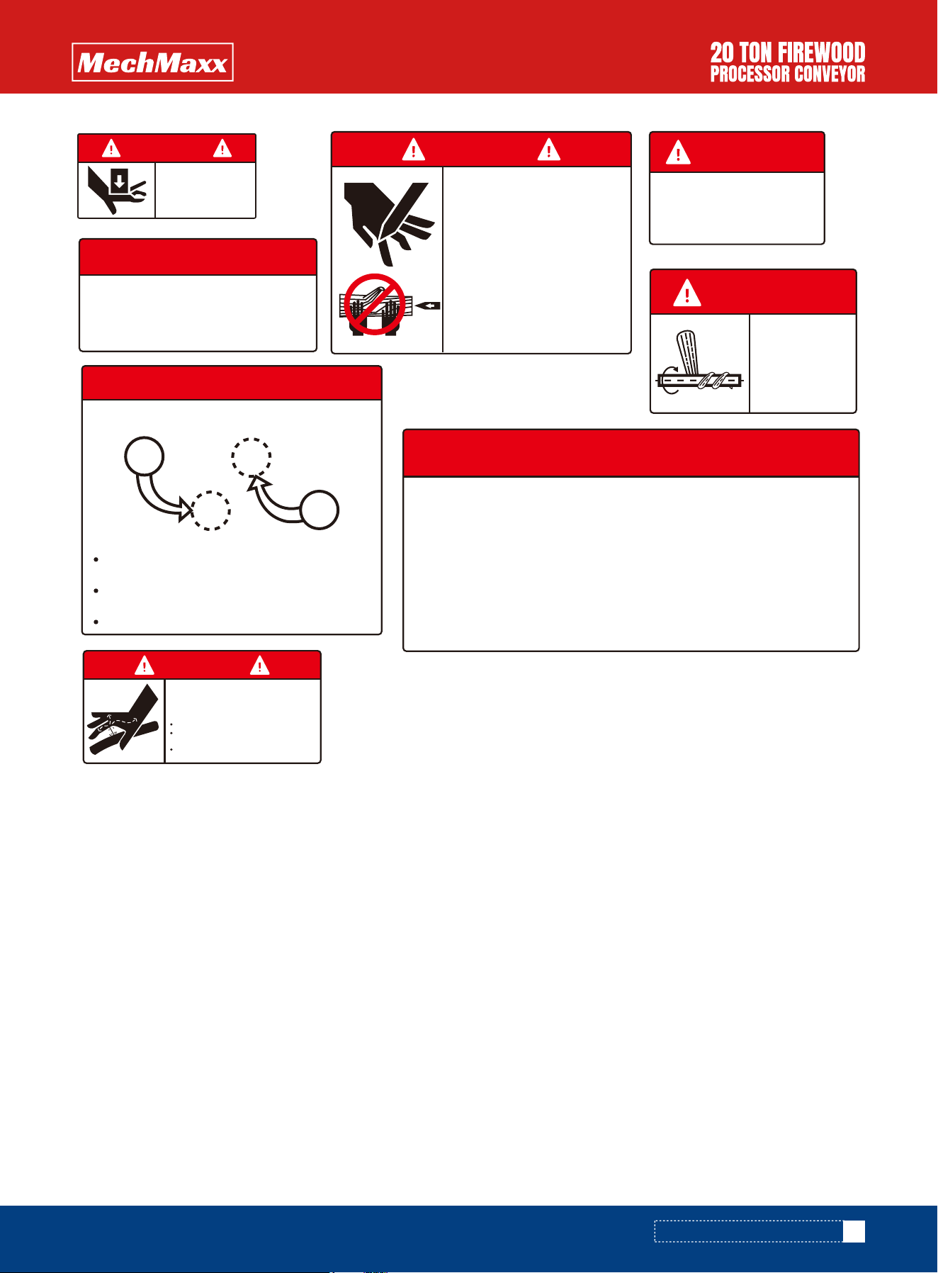
WARNING
SERVICING MOVING
EQUIPMENT CAN
CAUSE SEVERE
INJURY
LOCK OUT POWER
BEFORE
MAINTENANCE
WARNING
MOVING PARTS
CAN CAUSE
SEVERE INJURY
STAY AWAY
WARNING
RETRACT WEDGE TO
REMOVE STUCK WOOD
KEEP HANDS CLEAR OF
WEDGE AND LOG
STRIPPER
LOG STRIPPER
PINCH POINT
MAX TOWING SPEED
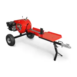
• Off road towing only, not designed for highway transporta-
tion
• Maximum towing speed: 45 MPH
• Latch coupler to 2" hitch ball
• Release tow bar stabilizing stand and securely lock in
position
• Attach safety tow chains to the tow vehicle
• Turn off the engine shut-off valve
TRAILER TOWING INSTRUCTION
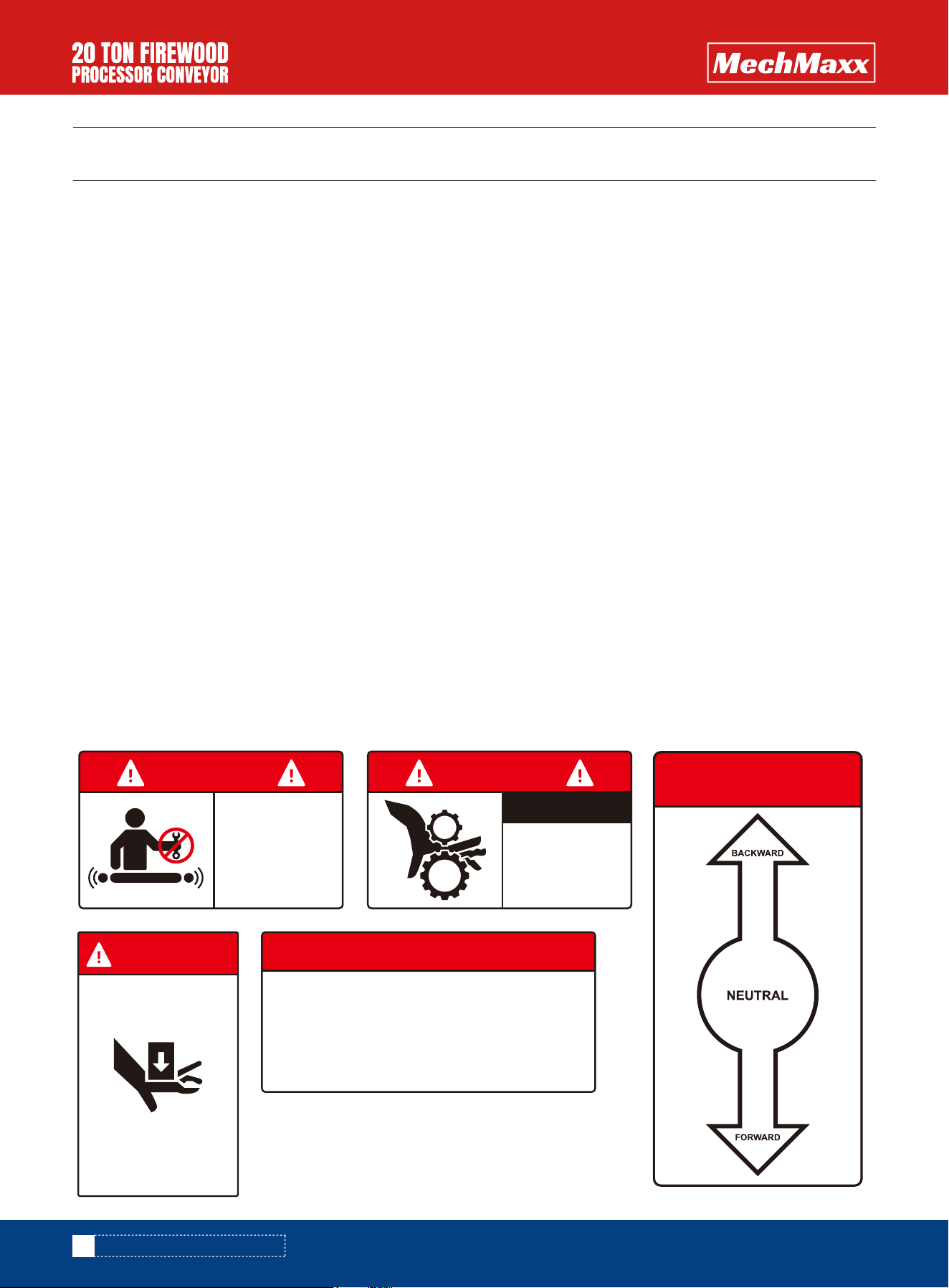
FEED CONVEYOR
BELT OPERATION
5
www.mechmaxx.com
GENERAL SAFETY INSTRUCTIONS
WARNING
STAY AWAY FROM HIGH PRESSURE
HYDRAULIC FLUID!
High pressure and temperature are developed in
the hydraulic system. Hydraulic fluid escaping
through a pin-size opening can cause skin damage
Inspect hydraulic system regularly for leaks
Never check leaks with hands while system is
pressurized
Seek medical attention immediately if injured by
escaping fluid
• Load log onto feeding conveyor belt
• Adjust to set the cut length
• Turn on conveyor "Forward" to feed log to the set position
• Pull chainsaw to cut the log
• When chainsaw returns back to its original position, the force ram starts to
move to push log forward
• Force ram returns back to its original position when it reaches the split
point
NOTE: Logs might stay and pile up in the V-groove. Clear off before next
split. Use the handle to operate force ram to clear piled up logs
INSTRUCTIONS FOR OPERATION
STABILIZING STAND
FOLD DOWN AND LOCK
THE STAND IN POSITION
BEFORE SPLITTING LOG
Moving parts can crush and cut. Pieces can fly out
while splitting. Follow safety procedures when
operating the splitter, otherwise serious injury could
occur
• Always completely read the owner manual before
operating the splitter
• Only one person can operate the splitter at one
time
• Do not operate the splitter when someone else is
helping to load the log
• Only operate the splitter when nobody else is
within 10 feet
• Operator must stay in the designated spot while
operating
• Only split wood along the same direction as the
wood grain
• Keep hands away from wedge, endplate, hydraulic
ram and split logs
• Do not leave splitter unattended during operation
• Do not set up splitter on slope or slippery surface
WARNING
WARNING
PINCH POINT
KEEP HANDS
CLEAR DURING
OPERATION
RETURNSPLIT
CLEAR OFF REMAINING LOGS IN V-GROOVE
Logs might stay in the V-groove. Use this handle to
clear off before next split
Push handle downward, force ram moves
forward to clear firewood
Force ram returns automatically when it reaches
the split point
Push handle upward, force ram retracts back
WARNING
ROTATING SHAFT
CAN CAUSE
SEVERE INJURY
KEEP HAIR AND
LOOSE CLOTHING
AWAY
WARNING
BEFORE REMOVING
SHIELD GUARD
LOCK OUT POWER
6
www.mechmaxx.com
Handle the disposal of the machine’s packaging material in an environmentally - friendly manner. Check that the machine
has not incurred any damage during transportation, and ensure that all necessary parts are included in the package. In
the event of any defects or damage, you should contact the retailer immediately.
Before commencing the lifting operation, ensure that no other persons or animals are within the
machine’s danger zone! And monitor the area and ensure that it stays empty for the entire duration
of the lifting.
ASSEMBLY
ASSEMBLY
CONTENTS SUPPLIED
INSTALLATION THE MACHINE
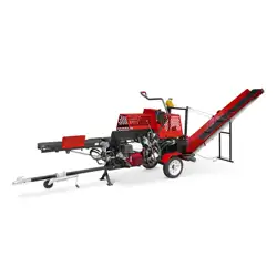
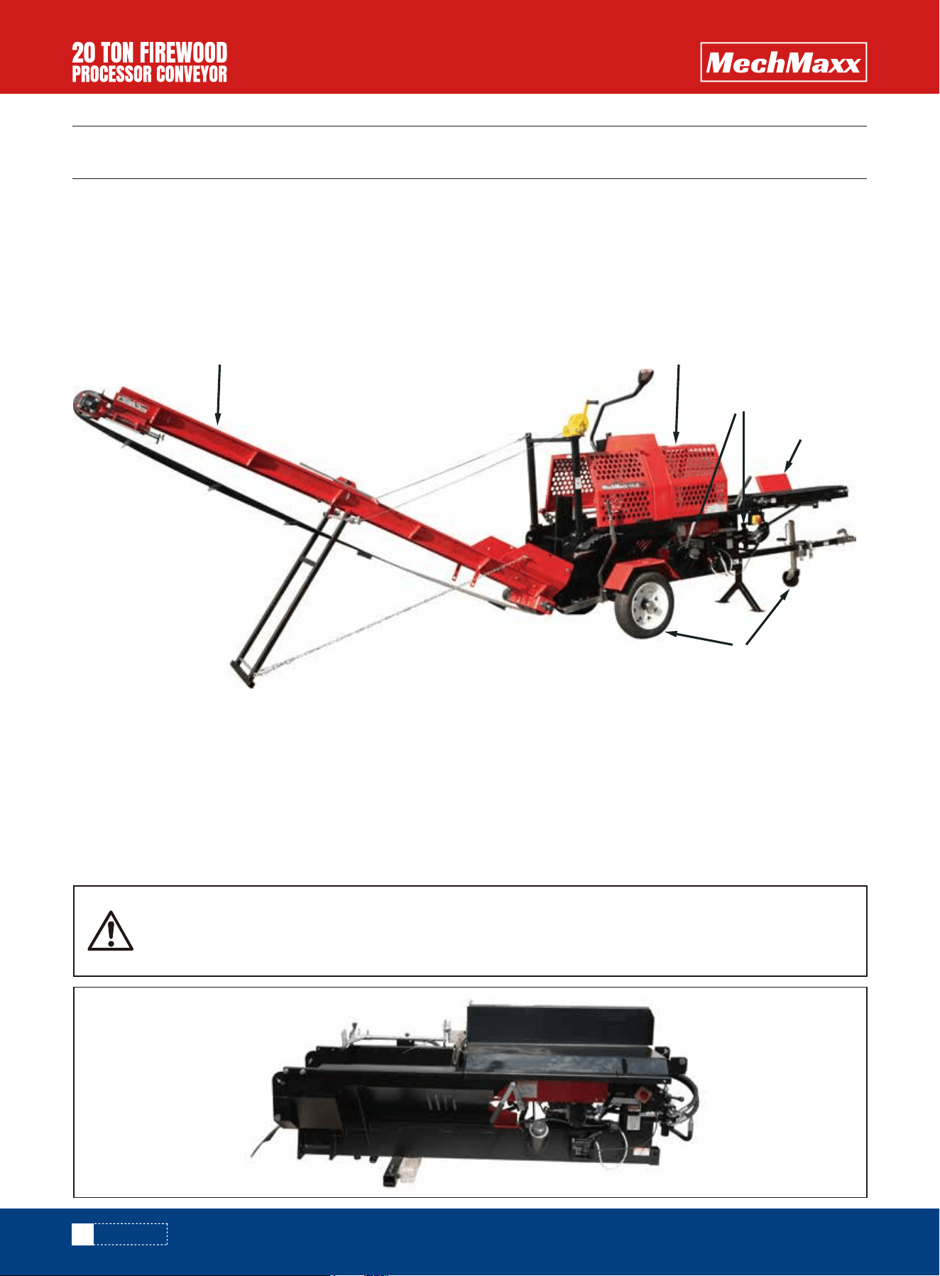
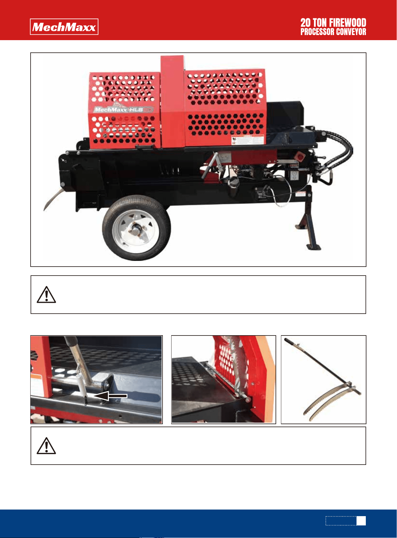
As the main components of the firewood processor are presented in the figure below
A. Output convey
B. Cutting and splitting unit
C. Control unit
D. Input conveyor
E. Trailer
1. Lift the Unit off the crate. If you are using straps, be careful not to bend or stress any components.
A B
D
C
E
7
www.mechmaxx.com
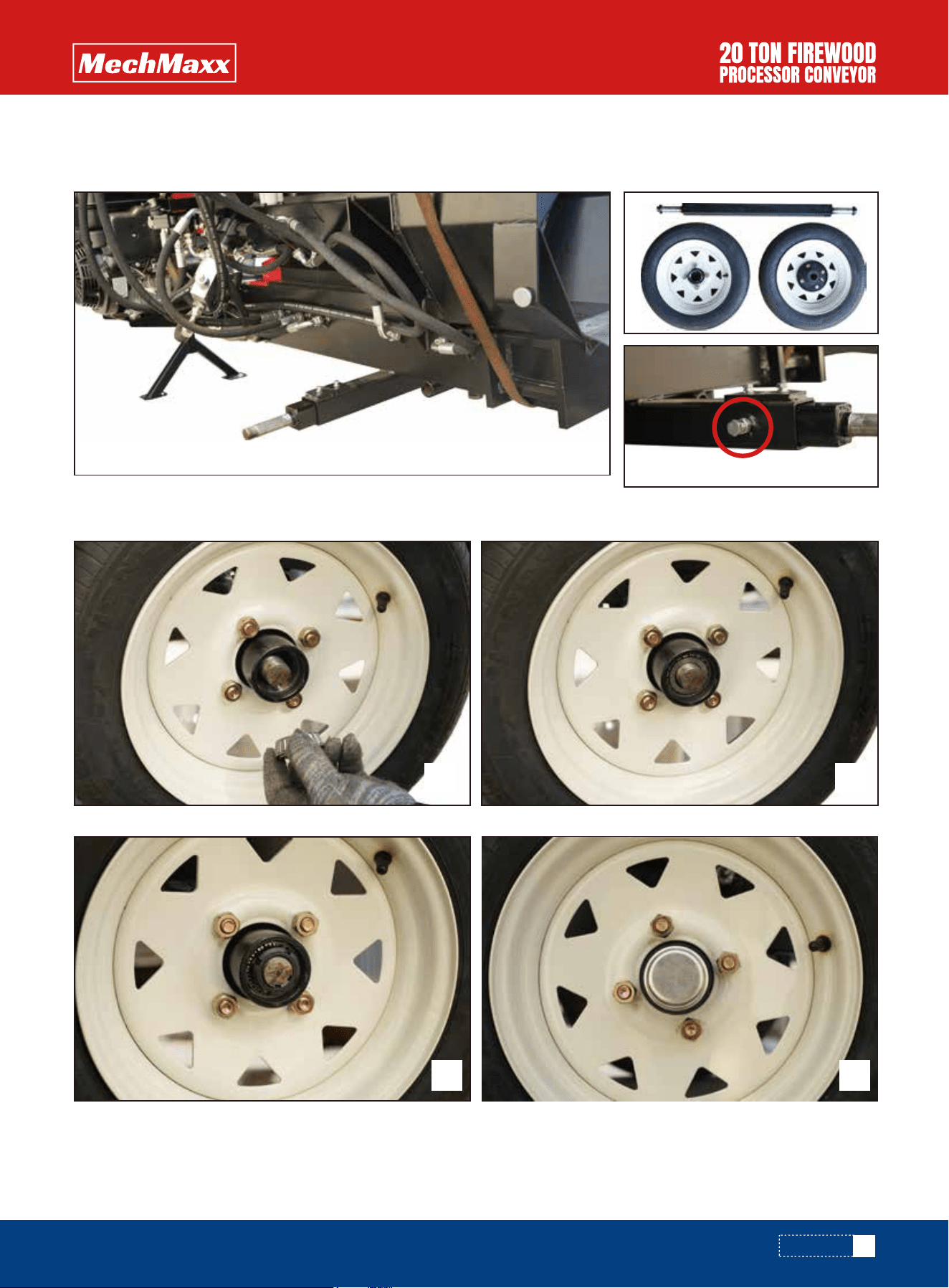
2. Locate the wheel axle and the two tires. Then install the axle into the square tube at the rear of the processor. Center
the axle in the housing and tighten the bolts.
3. Install each tire and its corresponding hub onto the axle and tighten the bolts.
ASSEMBLY
1 2
3 4
8
www.mechmaxx.com
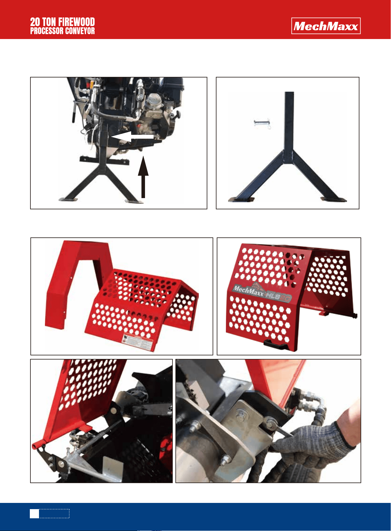
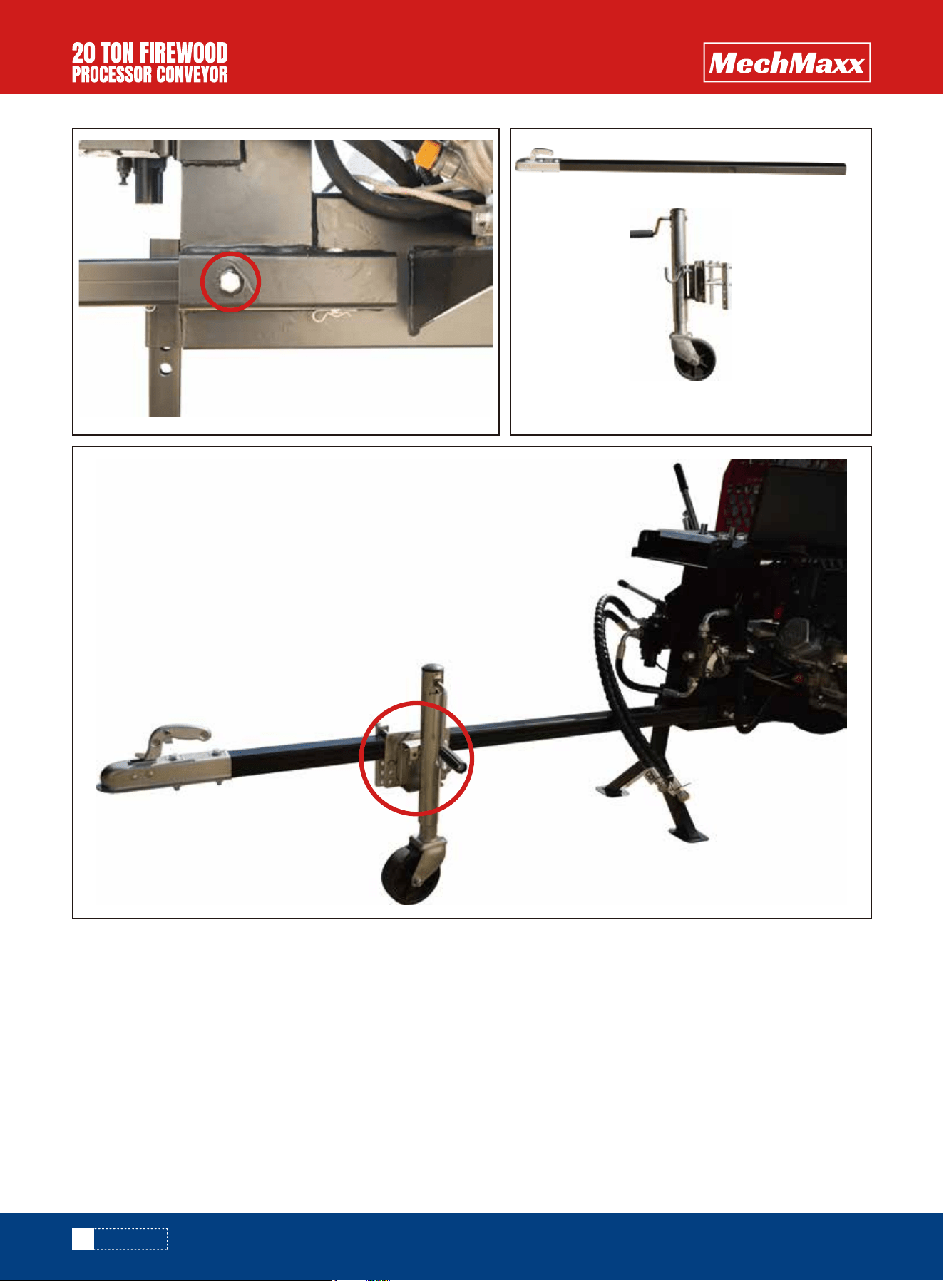
4. Install the tripod leg in the front mount. Pass the safety pin through (the relevant part) and secure the safety pin with
an R pin. Then lower the processor to the ground.
5. Install the sawing guard onto the appropriate location using 6 - 13mm nuts and bolts, ensuring that they are tightened
securely.
ASSEMBLY
9
www.mechmaxx.com
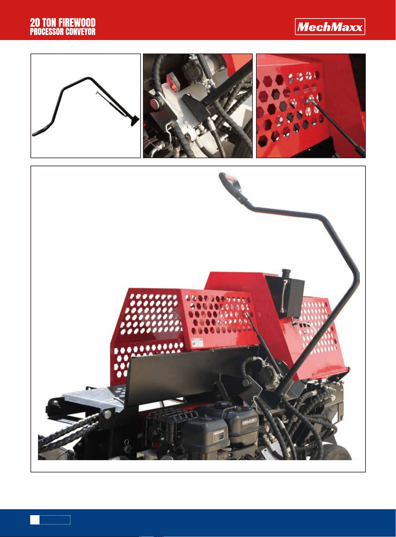
6. Install the wood gripper and tension spring in their designated positions.
7. Install the chainsaw arm to swivel plate with 3 bolts and nuts provided the bolts will be installed through the chain-
saw arm into the threaded holes on the swivel plate. screw the gas cylinder into the swivel head that is already mounted
to the sawing guard.
ASSEMBLY
Note: In order to effectively protect the surface from scratches, please separate the wood gripper
from the saw table with cardboard when installing the wood gripper.
After installing the log splitter guard, open and close it several times to check the normal operation
of the limit switch. When the log splitter guard is opened, the limit switch is pressed down; when it
is closed, the limit switch resets.
10
www.mechmaxx.com
ASSEMBLY
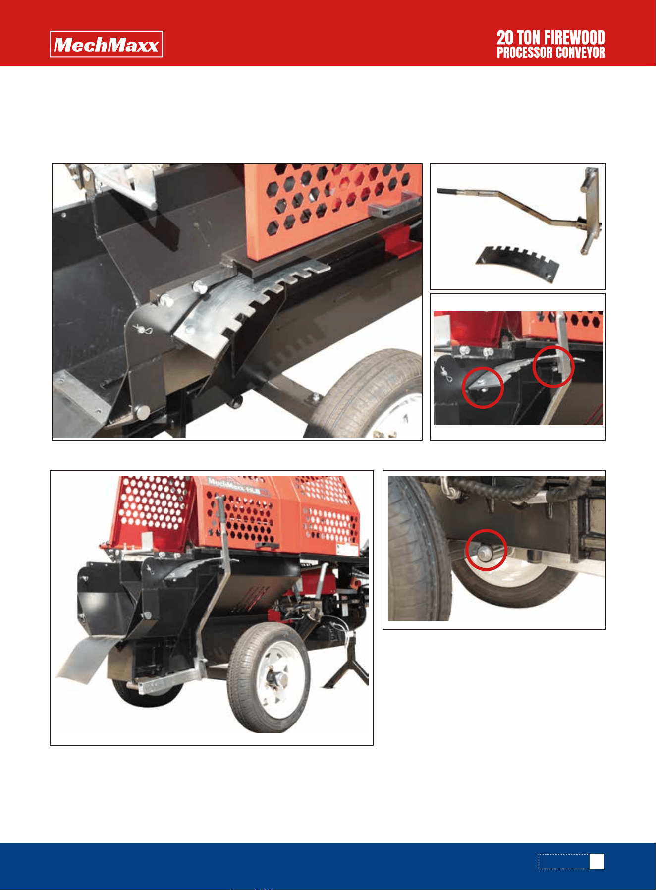
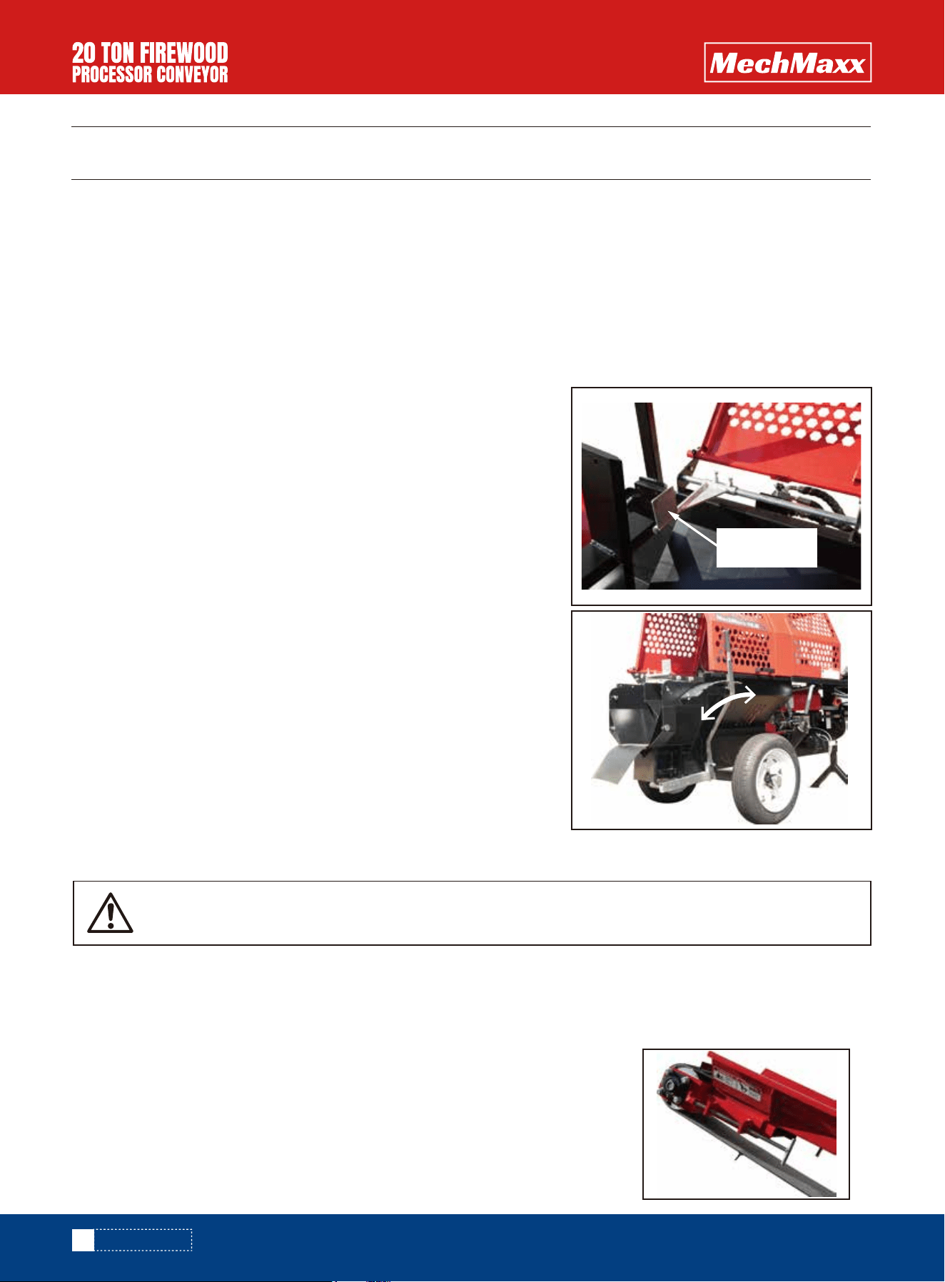
8. Install the adjustable wedge assembly.
8.1 Remove bolts and nuts from the side of the processor, install the wedge adjustment plate and tighten 2 bolts and
nuts.
8.2 Assemble the adjusting rod assembly.
9. Pull the adjusting rod into the position, then insert the wedge.
8.3 Slide the swivel bar through the mount behind the axle. Then tighten the bolt and washer.
11
www.mechmaxx.com
ASSEMBLY
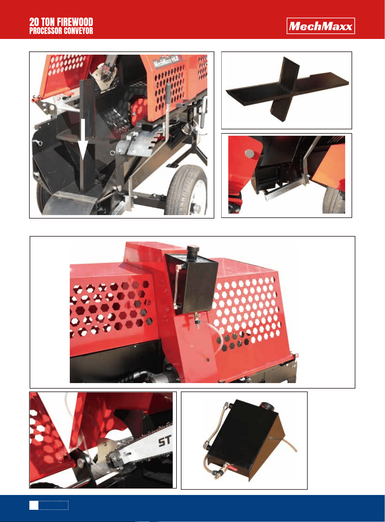
10. Install the chainsaw lubrication canister and connect it to the chainsaw.
12
www.mechmaxx.com
ASSEMBLY
11. Install the feed delivery system in the designated area of the equipment, following the alignment marks.
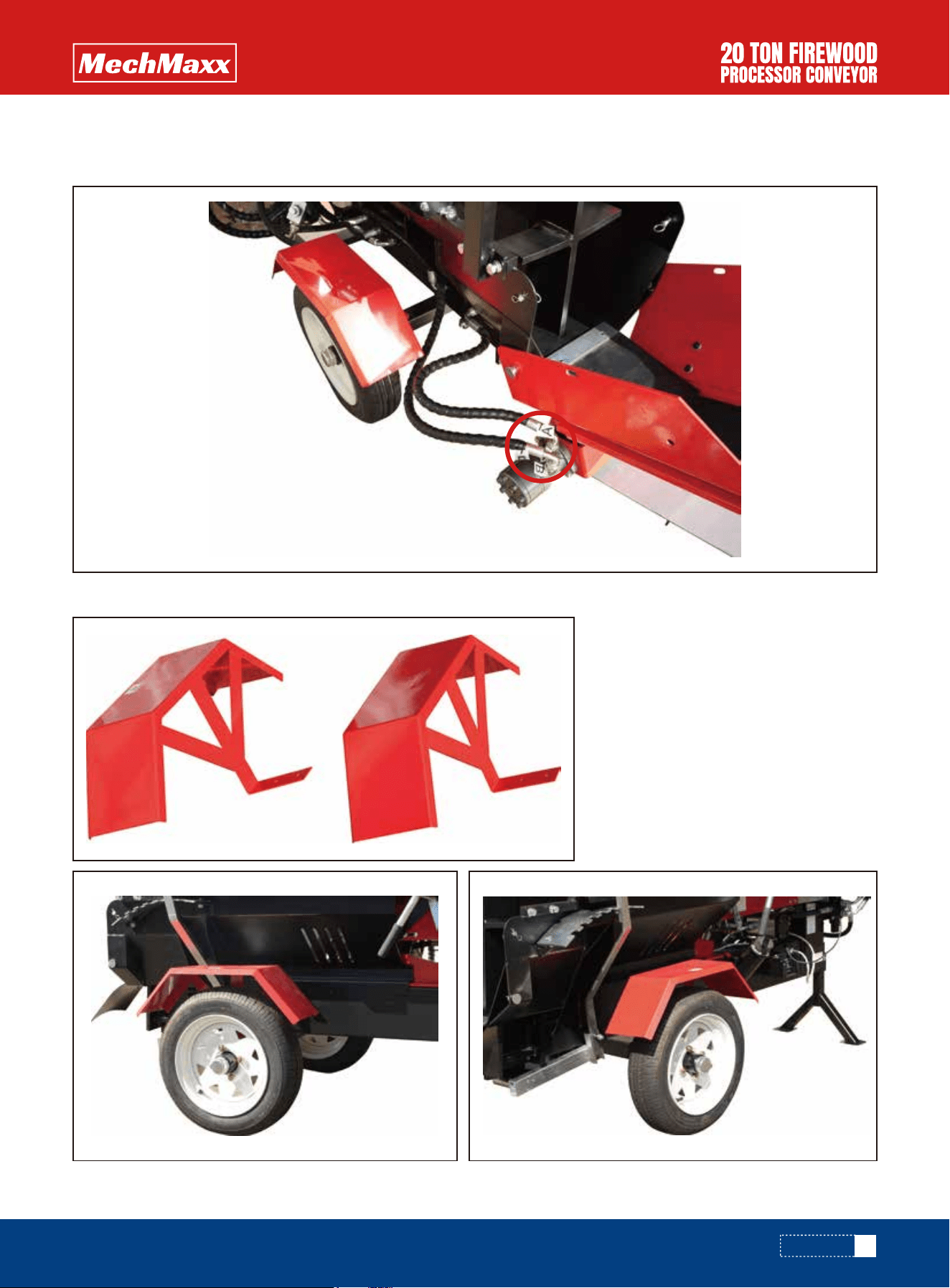
1. Connect the feed delivery system to the firewood processor. Pin a bolt through (the relevant parts) and secure it with
a cotter pin.
2.Install the trailer drawbar onto the main machine and secure it with bolts.
Installing the feed delivery system requires two people to work together. When connecting it to the
firewood processor, one person needs to hold or support the feed system using other objects until
the adjustment of the feed support rod is complete. And otherwise the feed system will fall, caus-
ing personal injury and machine damage.
13
www.mechmaxx.com
ASSEMBLY
14
www.mechmaxx.com
ASSEMBLY
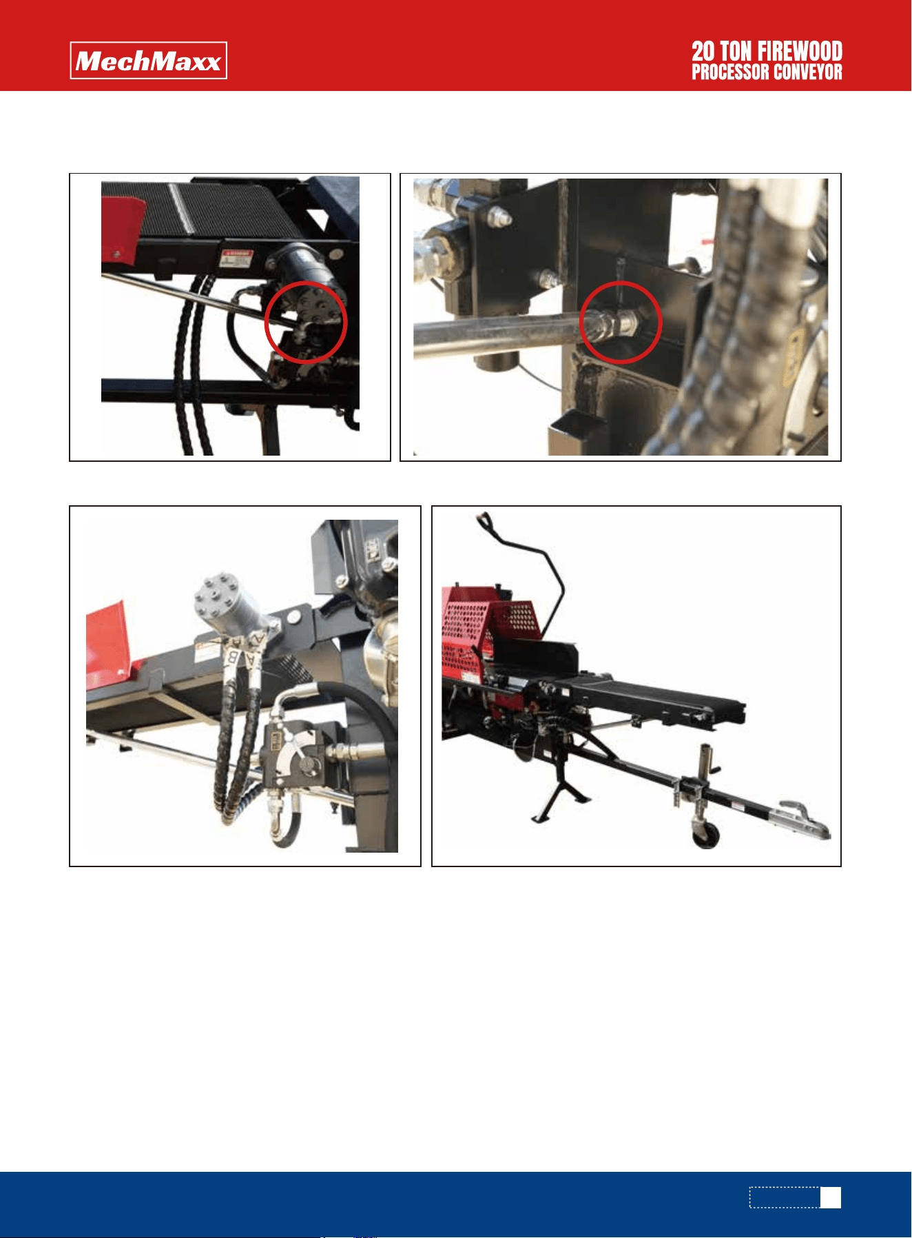
3. Insert the support rod into the specified position and rotate the end bolt of the support rod to level the feed delivery
system.
4. Install the feed damper and connect the hydraulic line to the hydraulic motor of the feed delivery system.
15
www.mechmaxx.com
ASSEMBLY
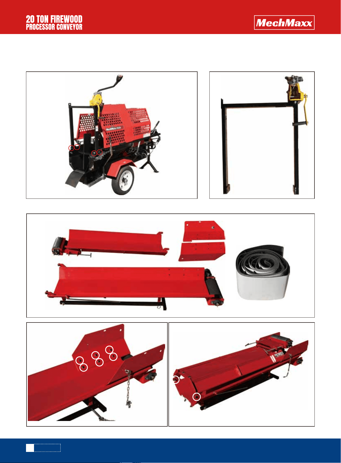
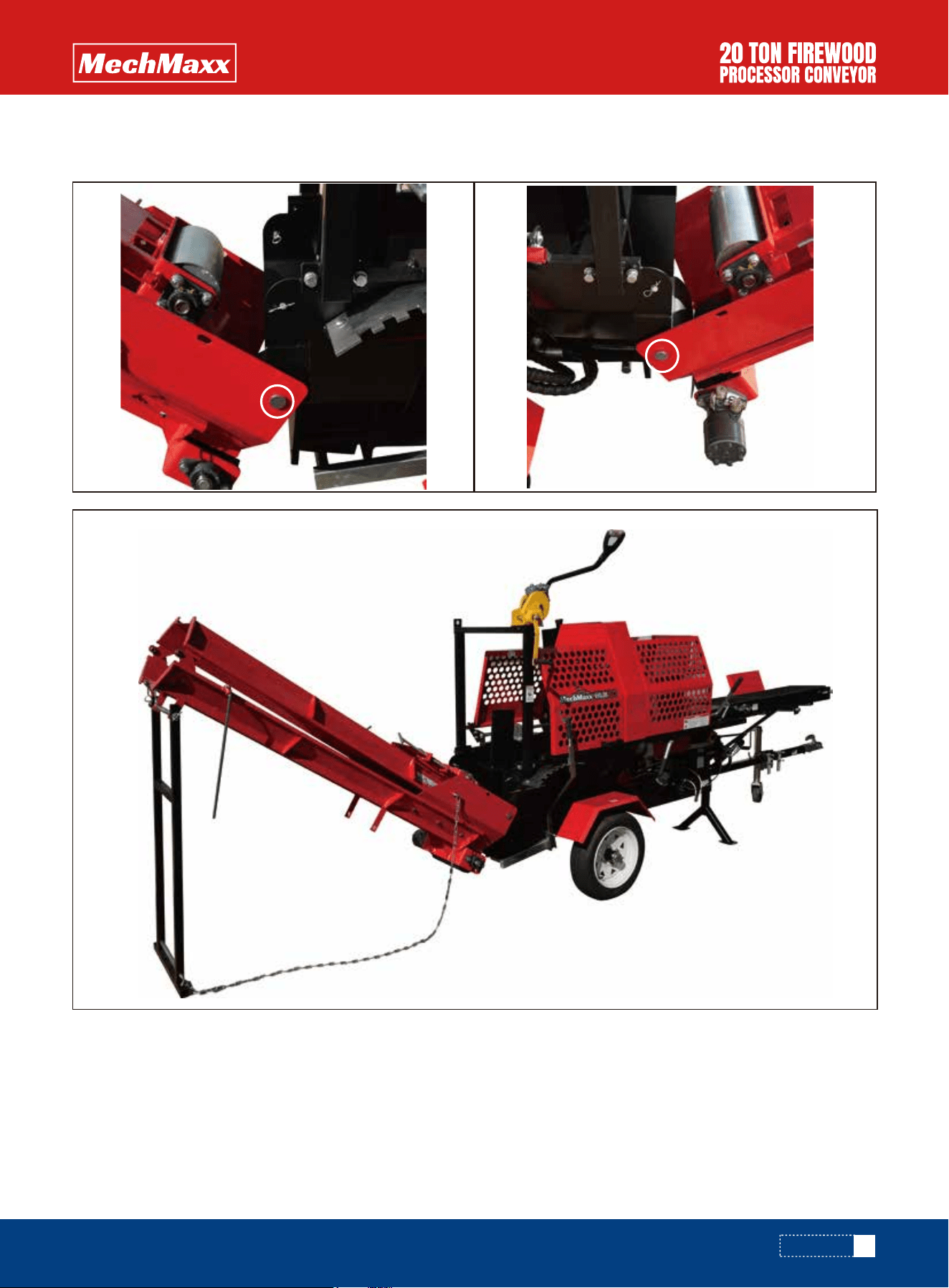
12.1 Mount the winch support arm to the processor with the 4 bolts provided.
12.2 Install the fixing plate on the conveyor base and tighten all bolts.
12. Install the discharge conveying system.
16
www.mechmaxx.com
ASSEMBLY
17
www.mechmaxx.com
12.3 Mount the conveyor base section to the rear of the processor using a pin to pass through and secure with a cotter
pin.
ASSEMBLY
18
www.mechmaxx.com
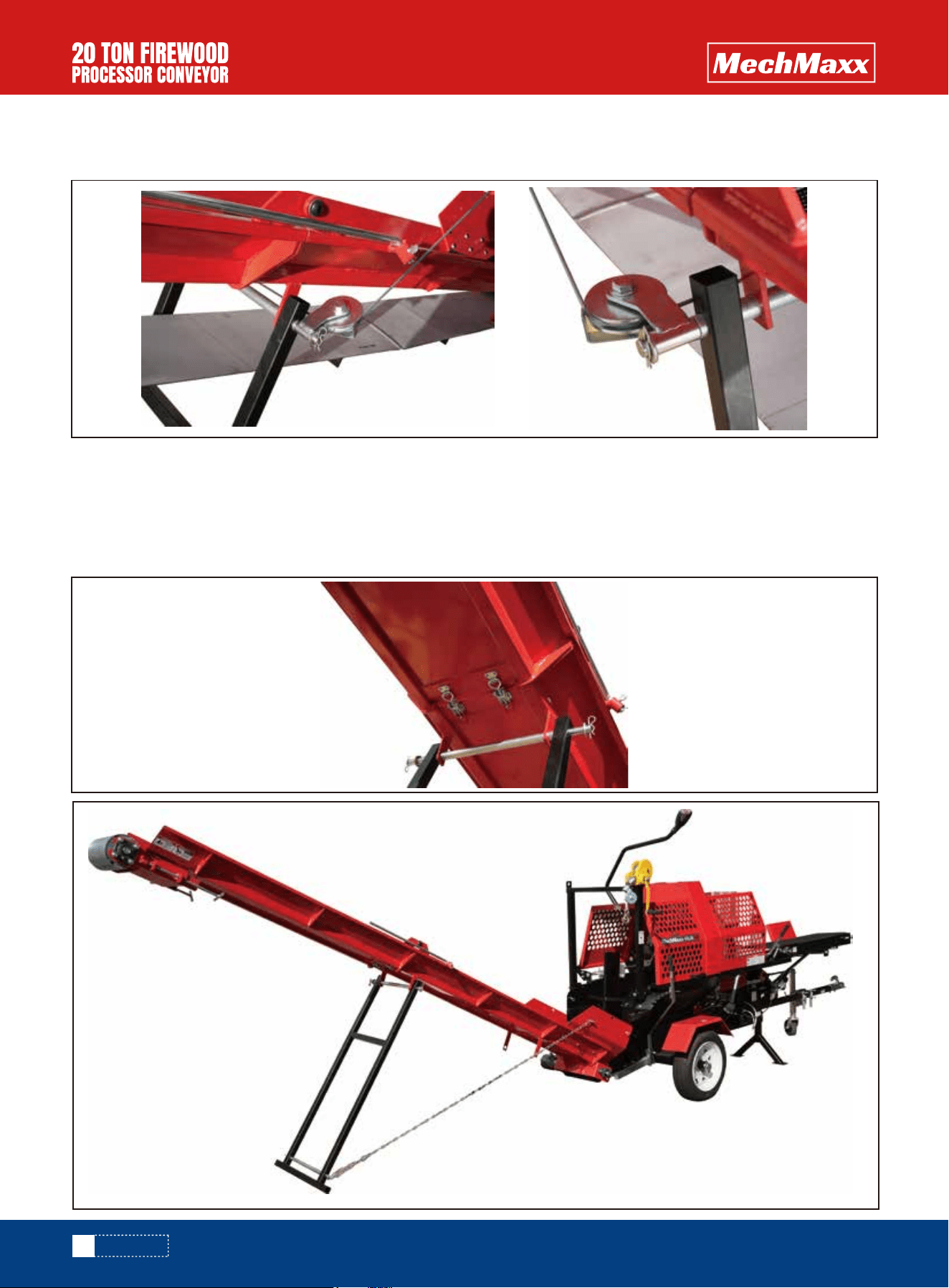
12.4 Lift the conveyor section up and line up the holes in the leg with the tab holes and push the support leg shaft
through. Loosen the winch cable, mount the rollers onto the pins, and then insert the R - pins.
12.5 Lift the leg and put the support leg fixed shaft through the leg and tabs to hold it in place. Lower the conveyor and
place the second section upside down on the first. Install bolts and washers at the swivel point. Remember that when
tightening the nuts, the conveyor section must be able to swivel, so do not tighten too much.
12.6 Lift and swing the upper section of the conveyor out and install the tail pulley support. When the conveyor is
extended for use, the adjustable buckle should be engaged.
ASSEMBLY
19
www.mechmaxx.com
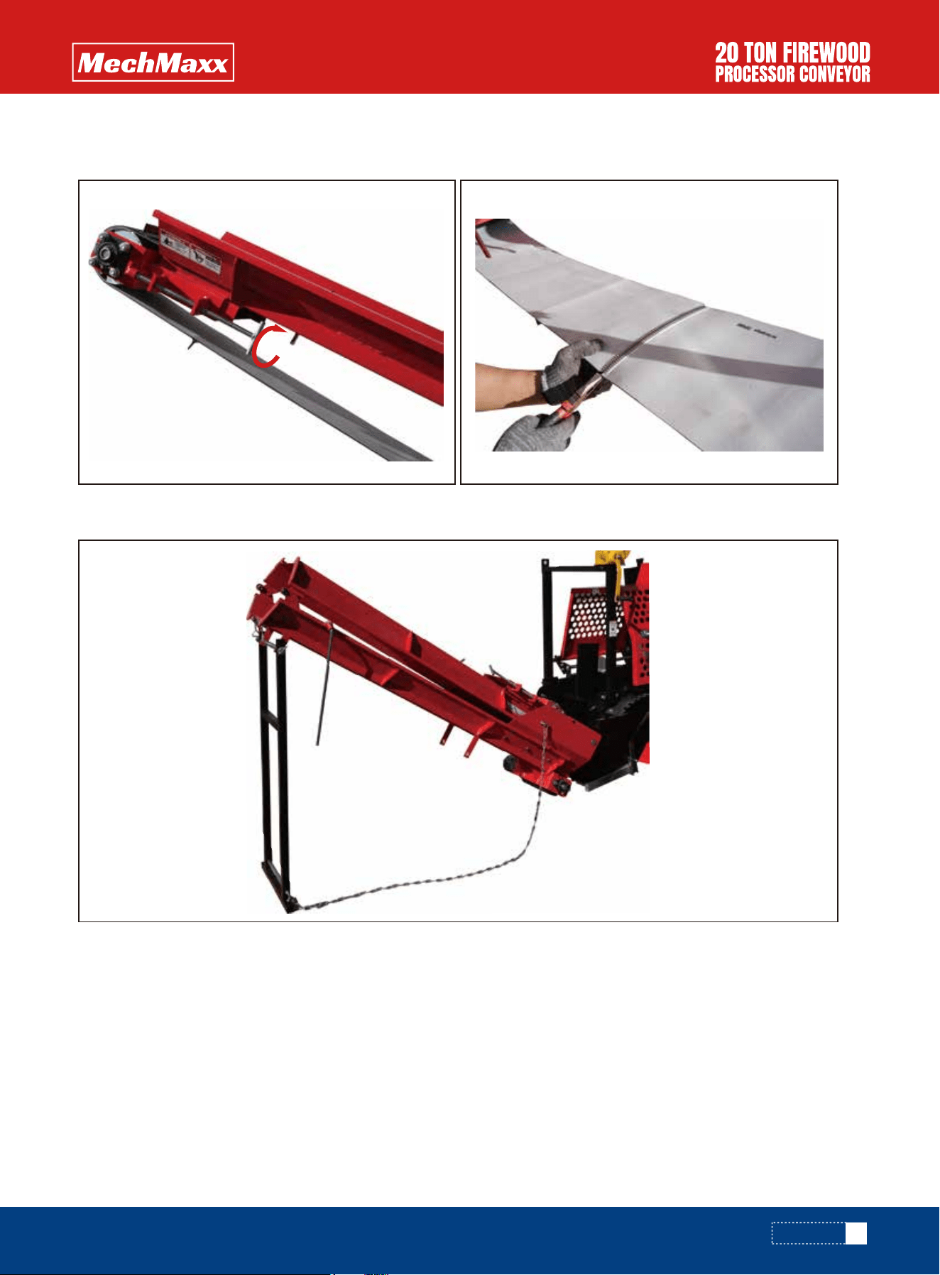
12.8 Install safety chains to avoid the leg toppling and protect the machine and personnel.
12.7 Install the conveyor belt. Connect the belt and put the pin through the lacing. Turn the adjusting bolts until the
conveyor is snug.
ASSEMBLY
20
www.mechmaxx.com
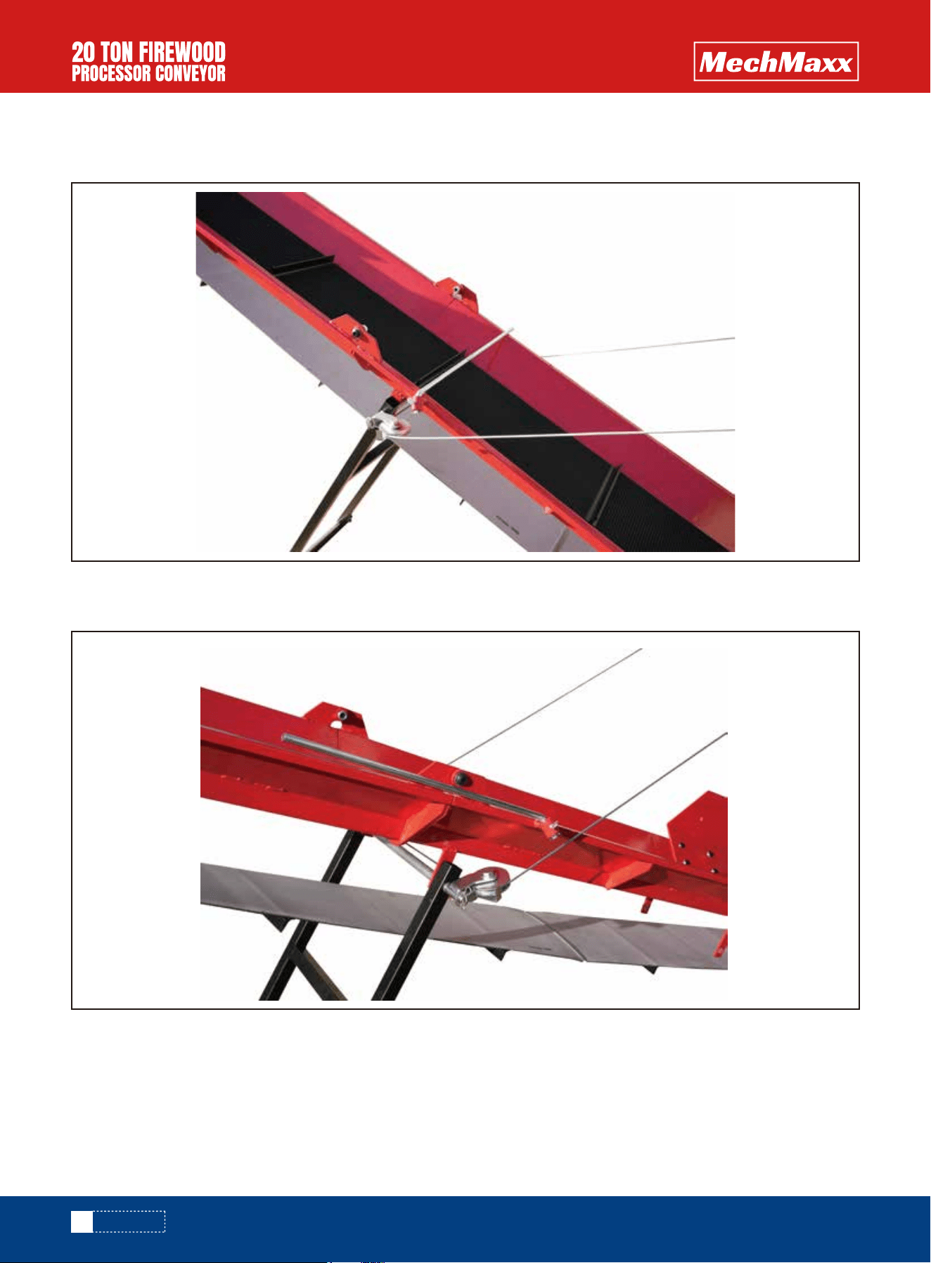
12.9 Install the belt support rod shown in this photo. It runs along the side of the conveyor and is used for retaining the
belt when the conveyor is in travel position.
The belt support rod is in its rest position in the photo and is out of the way of the belt, so the machine can be operated
as normal.
ASSEMBLY
21
www.mechmaxx.com
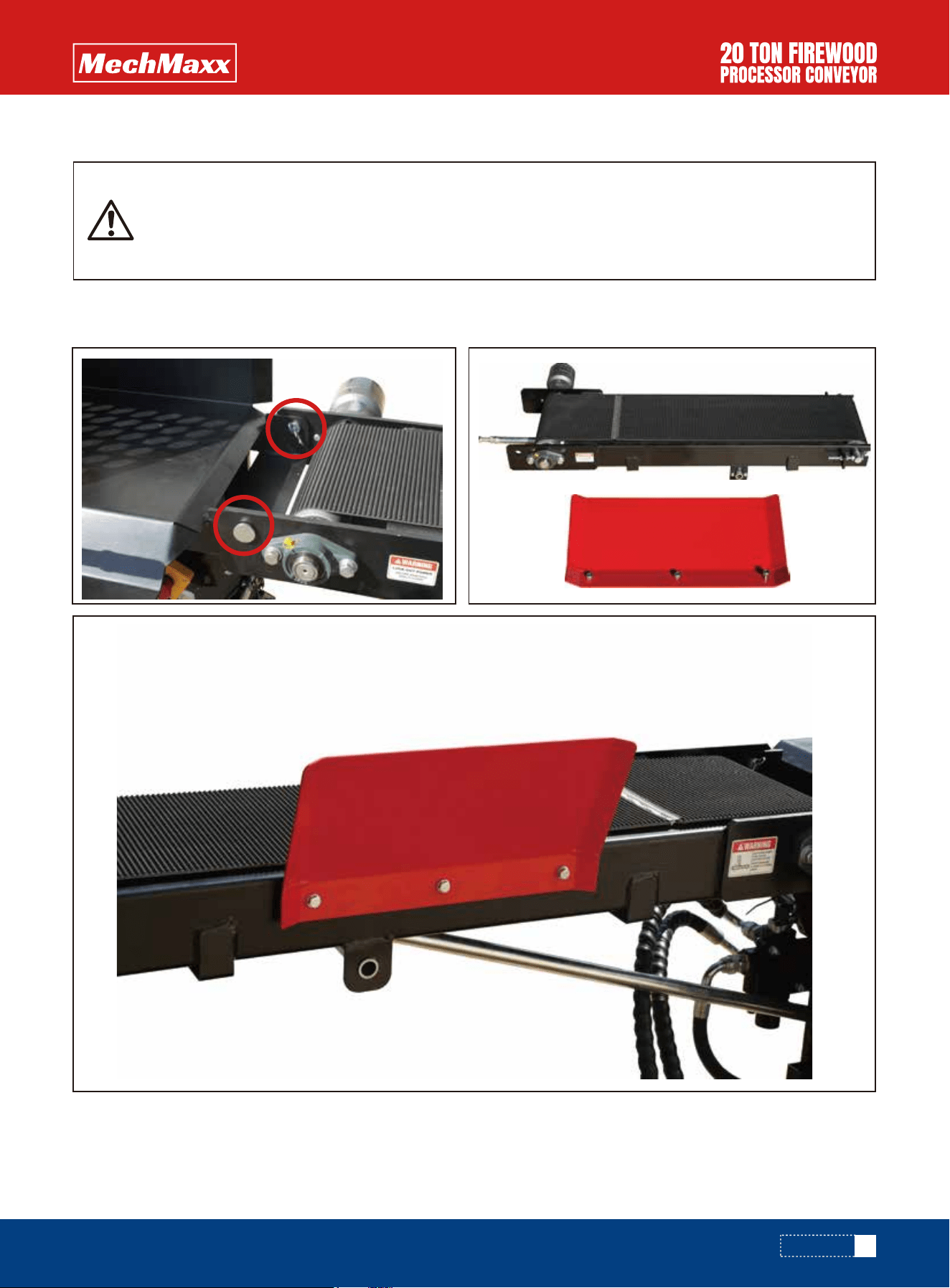
13.10 Install the extension plate onto the rear of the processor and connect the hydraulic line to the hydraulic motor of
the discharge conveying system.
12.11 Install the mudguard.
ASSEMBLY
1. Battery Connection
Always connect the cables in the following sequence to avoid possible shock.
a. Connect one end of the red (+) cable to the starter solenoid terminal of the compressor engine.
b. Connect one end of the black (-) cable to the mounting bolt, frame bolt of the engine, or other good engine ground
connection.
c. Connect the other end of the red (+) cable to the battery positive (+) terminal.
d. Connect the other end of the black (-) cable to the battery negative (-) terminal as shown.
e. Coat the terminals and cable ends with grease if they are to remain permanently connected.
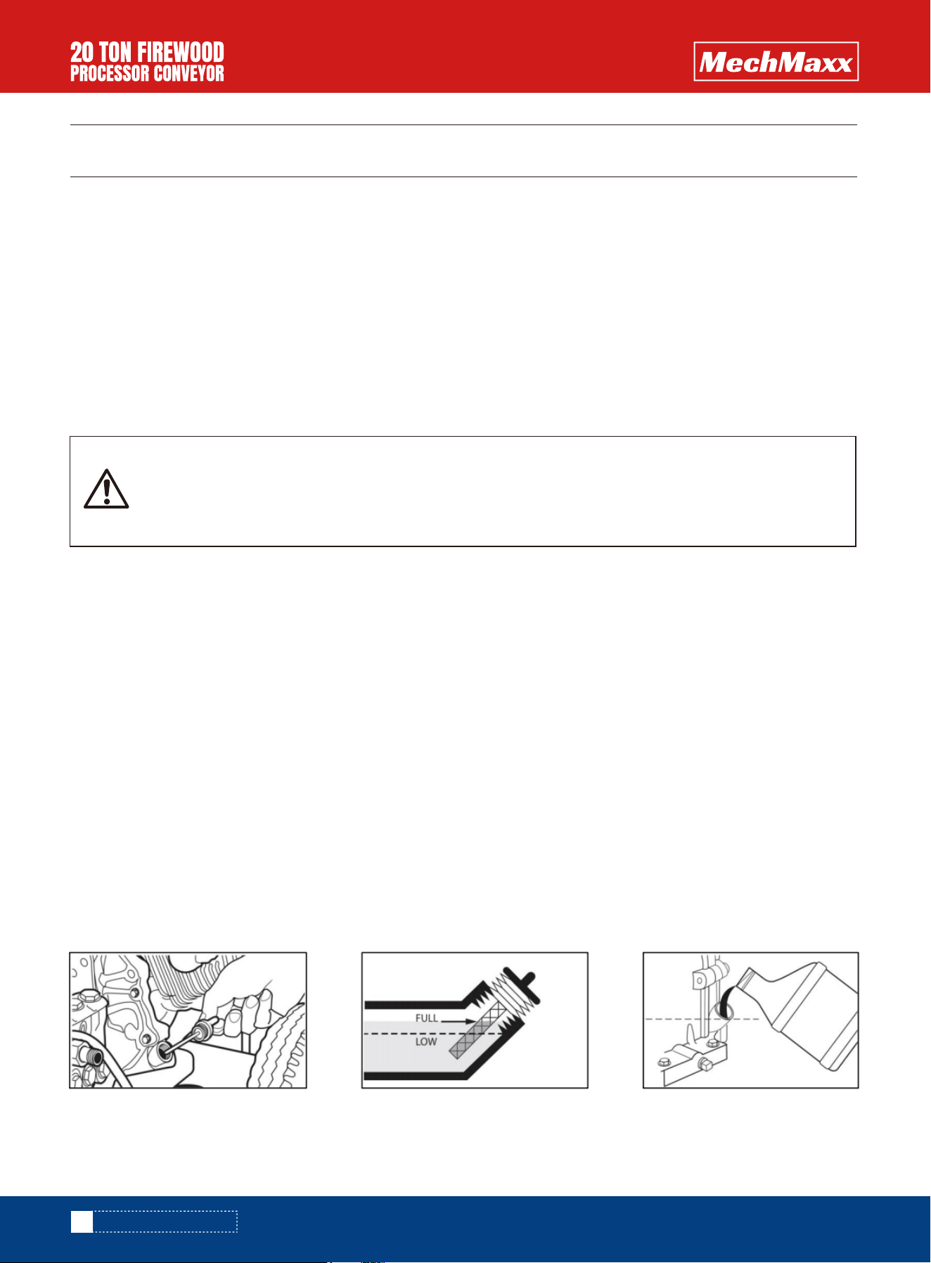
1. Add Oil To The Engine
Once the engine is operating, it will continue to run whether the battery is connected or not. The battery should be discon-
nected from the engine when the processor is not going to be used for a long period of time. Always disconnect the cables
in the reverse sequence of the above connection sequence.
a. First, place the pressure washer on a flat, level surface.
b. Next, clean the area around the oil fill and remove the yellow oil fill cap.
c. Then, if an oil funnel is available (optional), slowly pour the contents of the provided oil bottle into the oil fill opening.
d. Finally, replace the oil fill cap and fully tighten it.
a. First, disconnect the black (-) cable from the battery negative (-) terminal.
b. Next, disconnect the red (+) cable from the battery positive (+) terminal.
c. Then, disconnect the black (-) cable from the grounding connection.
d. Finally, disconnect the red (+) cable from the starter solenoid terminal.
22
www.mechmaxx.com
SETTING UP BEFORE USE
SETTING UP BEFORE USE
CONNECT the TERMINAL to the BATTERY.
ENGINE
2. Battery Disconnection
Be careful not to connect the battery with reverse polarity, as this will short - circuit the battery
charging system. Since the engine has not yet been grounded to the battery ground, your uninsu-
lated tool handles can cause a short - circuit if they also touch a grounded part while you are tight-
ening the positive battery cable end.
2. Add Fuel To the Engine
a. First, place the pressure washer on a flat, level surface.
b. Next, clean the area around the oil fill and remove the yellow oil fill cap.
c. Then, if an oil funnel is available (optional), slowly pour the contents of the provided oil bottle into the oil fill opening.
d. Finally, replace the oil fill cap and fully tighten it.
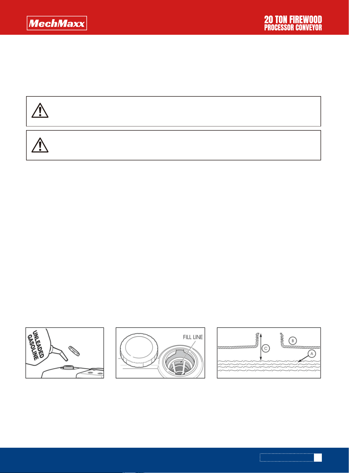
WHEN ADDING FUEL TO THE ENGINE, OBSERVE THE FOLLOWING STEPS:
1. Turn the engine OFF and let it cool for at least two minutes before removing the fuel cap. Loosen the fuel cap slowly
to release pressure.
2. Fill the fuel tank outdoors.
3. DO NOT overfill the fuel tank. Leave space for fuel expansion.
4. Wait for spilled fuel to evaporate before cranking the engine.
5. Keep fuel away from sparks, open flames, pilot lights, heat, and other ignition sources.
6. DO NOT light a cigarette or smoke near an open fuel tank or container.
7. Clean the area around the fuel fill cap and slowly remove the cap to allow any pressure to escape.
8. Slowly add unleaded gasoline (A) to the fuel tank (B). Be extremely cautious not to fill the fuel above the baffle (C).
This allows appropriate space for fuel expansion.
9. Install the fuel cap and allow any spilled fuel to evaporate before starting the engine.
DO NOT use unapproved gasoline such as E85 (85% ethanol/15% gasoline).
DO NOT mix oil with gasoline.
DO NOT modify engine to run on alternate fuels.
If engine doesn’t run properly after fueling, switch fuel brands. The engine is certified to run on gasoline. The emission
control system for this engine is EM (Engine Modifications).
23
www.mechmaxx.com
SETTING UP BEFORE USE
Failure to use fuel as recommended in this manual will void the warranty.
Fuel and fuel vapor are extremely flammable and explosive. Fire or explosion from misuse of fuel
can cause severe burns and even death.
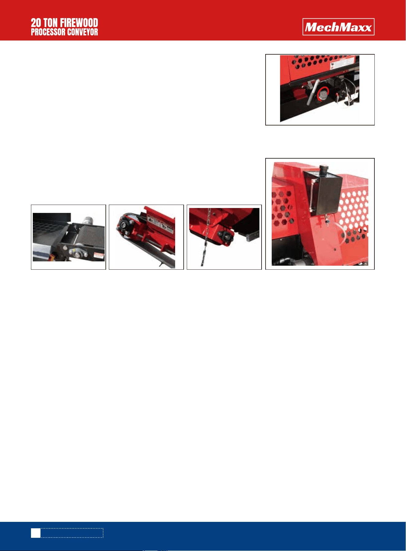
1. Open filler cap of the hydraulic oil tank.
2. The hydraulic tank capacity is 26 l. you only add the 20l into the tank. Noted:
Add 26L AW32 hydraulic oil, in cold climates AW22 can be used and in hot condi-
tions AW46 can be used.
3. Close filler cap of the hydraulic oil tank.
All of the firewood processor's lubrication points require Vaseline. There are four
lubrication points:
1. Grease nipple of the input conveyor drive roller.
2. Nipples (3 pcs) of the output conveyor's drive roller.
ADD THE HYDRAULIC OIL.
Add the saw chain lubrication
LUBRICATION
24
www.mechmaxx.com
The input conveyor belt or feed roller feeds the wood to be processed into the machine. Feed wood into the machine
using control lever A.
When feeding wood into the machine, ensure that your clothes, hands or other body parts are not at risk of getting
caught, for example, due to the log's shape. Do not use your hand to guide the log into the cutting section. Adjust the
measuring device to the desired measurement.
1. Choose the log to process. Note that the maximum log diameter is 38 cm. The knottiness and shape of the log can
increase the diameter.
2. The input conveyor belt can be driven forward by pressing lever A downward, especially when the log is further away
from the cutting section and a longer and continuous feed motion is required.
3. Once the log stops for cutting in the mechanical measuring device, lock the log in place with the wood gripper by
pressing down handle B.
4. Cut the log by pulling down lever C, which activates the saw chain and lowers the saw bar. After sawing through the
wood, return the saw bar to the upper position by pushing up lever C.
5. Pull down lever D to move the splitting beam forward and split the log.
6. Simultaneously, press lever A downward, pushing the log into the cutting chamber for the next cycle of operation.
Re - splitting or splitting without cutting
WOOD FEEDING, CUTTING AND SPLITTING
SETTING UP BEFORE USE

25
www.mechmaxx.com
Raise the guard of the cutting and splitting section.
Place the log you want to split in the splitting groove.
Close the guard of the cutting and splitting section.
Move the splitting beam forward for the desired length by pressing down lever D and return the splitting beam back-
ward by pushing up lever D.
The above procedure can be used to split wood without cutting it.
Note! Placing logs directly on the input table with a loader is strictly prohibited.
Note! Ensure that the log's centre of gravity stays on the conveyor.
Sawing the last log
When sawing wood, the second to last piece should be sawn in such a way that the remaining piece is of a sufficient
length. This ensures that the log will stay firmly under the wood gripper and that the sawing will be steady and safe.
The firewood processor’s discharge conveyor belt is driven by a hydraulic motor. The maximum operating angle for the
discharge conveyor is 40°. The maximum angle is indicated on the label and the instructions attached to the discharge
conveyor.
If the conveyor is jammed for any reason, the machine must be shut down before removing the cause. There must be at
least 50 cm between the end of the output conveyor and the pile of processed firewood.
1. After you have finished making firewood, stop the output conveyor, shut down the machine and remove the firewood
from the splitting groove and conveyor.
2. Ensure that the machine has not been damaged.
3. Position the output conveyor so that the conveyor and firewood processor can be moved safely off the processed
firewood.
4. Clean the machine.
USING THE DISCHARGE CONVEYOR
AFTER USE
If you will not be using the firewood processor for a while, do the following:
5. As necessary, carefully move it to a location where you can place the input and output conveyors as well as the
working platform into their transport and storage positions.
6. Place the conveyors into the transport and storage position.
7. Clean the machine and carryout any maintenance.
SETTING UP BEFORE USE

Names and functions of the controls
A. Feed conveyor control lever
- The feed conveyor belt rotates forward by moving the lever downward.
B. Wood gripper control lever
C. Cutting control lever
- When the control lever is depressed, the chainsaw begins to turn and cut the wood. When the cutting is complete, and
the control lever is lifted to the original position, the chainsaw stops turning and the cutting is finished.
D. Splitting control lever.
- Push the handle downward, and the force ram moves forward to clear firewood.
- The force ram returns automatically when it reaches the split point.
- Push the handle upward, and the force ram retracts.
E. Height adjustment of the splitting knife.
OPERATING
MACHINE CONTROLS AND FUNCTIONS
Before the actual operation of the machine,a test run and functional test must be carried out. Both
the test run and testing can only be performed by a person who has studied the machine’s manual.
26
www.mechmaxx.com
C
B
E D A
OPERATING

Before using the machine, the operator must ensure that the machine has not sustained any damage.
•The machine is positioned on a solid foundation.
•No unauthorised persons are within the machine’s danger zone.
•All guards and safety devices are in place and functional.
•Opening the splitting and cutting guard will stop the machine's hazardous functions. This is an important safety feature.
•The hydraulic hoses and pipes are undamaged. The pipes must be replaced if there is a tear in the hoses or pipes, if they
leak, or if the surface layer of the hydraulic hose has worn all the way down to the supporting weave.
•The machine does not leak oil.
•The machine functions properly.
•The emergency stop switch works properly.
1. Check that the guard for the firewood processor's splitting section is down.
2. Check that the input and output conveyors are in the operating position.
3. Ensure that the splitting groove is empty. And ensure that the emergency stop switch works properly.
4. Make sure that you are familiar with the functions of the machine's controls.
5. Start the engine.
6. Press down control lever C. The chain saw will start to rotate. Press it down to the lowest position and observe the
chain saw's rotation. Check that the bottom of the chain saw is below the saw platform.
7. Start the splitting motion by pushing up lever D. The splitting beam should move forward when pushing the lever up and
stop immediately when the lever returns to the initial position. It should move backwards when pulling the lever down and
also stop immediately when the lever returns to the initial position.
8. Do the following to ensure that the saw chain lubrication functions automatically:
a. Use lever C to perform a few sawing motions without any actual logs.
b. Turn off the machine and disconnect it from the power source.
c. Open the guard and see if the saw chain has been supplied with oil.
Note! In cold weather, the saw valve shaft may be sluggish at first, which means that the saw bar
must be driven to the bottom position a couple of times for the saw chain to run.
9. Move the splitting beam forward and stop it by opening the cradle guard of the splitting section.
10. Ensure that the splitting beam moves backwards by pushing upward lever D.
11. Test run the feed motion of the input conveyor by pressing lever A downward.
12. Visually check that the output conveyor runs at normal speed.
13. Ensure that the splitting motion or saw chain cannot be activated with the guard open.
If a fault occurs during the test run, determine the cause of the fault and take remedial action as deemed necessary. The
machine must be shut down and disconnected from the power source for the duration of both the diagnostics and repairs.
PERFORMING A TEST RUN ON THE MACHINE
Before the test run, all of the components of the firewood processor must be checked. If any faults
or wear and tear that may affect the safe use of the machine are discovered, the processor must
not be used until the faulty or worn component is replaced and safe use can be ensured.
Note! Do not use the machine if the requirements listed above are not met!
Note! Do not leave a running machine unsupervised!
27
www.mechmaxx.com
OPERATING
28
www.mechmaxx.com
MAINTENANCE
MAINTENANCE
Exercise extreme caution when handling the knife, and wear protective gloves.
DISCONNECTING THE MACHINE FROM ITS POWER SOURCE
ADJUSTING THE LOG LENGTH
HEIGHT ADJUSTMENT OF THE SPLITTING KNIFE
The machine must be disconnected from its power source before maintenance, adjustment, replacement or cleaning.
Only use spare parts supplied by the manufacturer or your retailer. If the guards of the machine have to be removed for
maintenance, they must always be reattached before activating the machine.
Ensure that the machine is inactive.
Once you have disconnected the machine from its power source, always ensure that the machine is completely inactive
before performing any other measures!
The firewood processor is equipped with a mechanical log measuring
device with an incremented adjustment value of 10 to 60 cm.
1. Turn off the machine, disconnect it from any power source, and open
the protective cover of the machine.
2. Loosen the retaining bolts, then set the wood limiter in the splitting
section to the desired length.
3. Re - tighten the retaining bolts.
The splitting knife can be controlled mechanically by moving control lever
E up or down. The splitting knife can be raised by moving lever E to the
right and vice versa. Logs should always be as centred as possible when
passing the knife, in order to keep the size of the firewood consistent.
The knife can be driven to the lowest position in one go by raising the
knife and clearing the space under the knife of firewood. The machine
must be shutdown and disconnected from its power source for the
duration of the cleaning.
1. Turnoff the machine and disconnect it from its power source.
2. Remove any firewood under the splitting knife and lower it to the lowest position using lever E
3. Open the guard and lift the splitting knife out of its slot. Install a new splitting knife by reversing the above steps.
The tightness and alignment of the discharge conveyor belt can be adjusted
using T-screw. Loosen adjustment T-screw on the side you wish the belt to run.
REPLACING THE SPLITTING KNIFE
ADJUSTING THE TIGHTNESS AND ALIGNMENT
OF THE DISCHARGE CONVEYOR BELT
Stopper
29
www.mechmaxx.com
MAINTENANCE
Replacing and tightening the saw chain
If the cutting blade of the machine does not penetrate the wood properly or the cut is skewed, the saw chain is most
likely blunt. It is a good idea to keep a replacement chain handy, so that you do not need to interrupt your work to
sharpen the chain.
When checking the tension of the saw chain, wear protective gloves. Pull the lower edge of the chain. The tension is
correct if you can pull out three to four teeth of the chain into full view by applying moderate force.
Note! Use protective gloves when handling the saw.
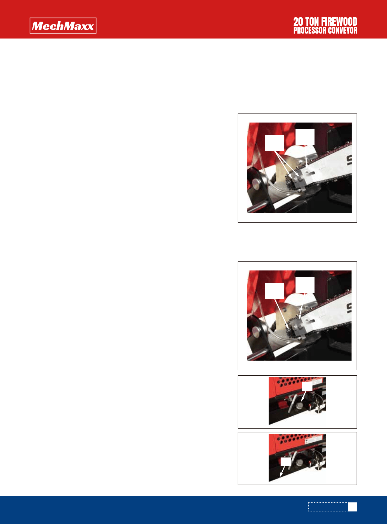
Replace the saw bar as follows:
1. Remove the saw chain according to steps 1-5 of “Replacing and
tightening the saw chain” .
2. Remove the saw bar bolts (2 pcs) and remove fastening plate A
3. Remove the saw bar from the groove.
4. Place the new bar against gearwheel B, twist it into the groove and
loosely attach the saw bar bolts and fastening plate A.
5. Attach and tighten the saw chain according to steps 6-8 in “Replacing
and tightening the saw chain”
1. Turn off the machine and disconnect it from its power source.
2. Open filler cap A of the hydraulic oil tank (this will allow the oil to drain
more easily).
3. Open drain plug B and drain the oil into a suitable container.
4. Tighten plug B firmly, and fill the tank with fresh oil (approx. 20 l).
Replace the saw chain as follows:
1. Turn off the machine and disconnect it from its power source.
2. Open the guard.
3. Loosen saw bar bolts A.
4. Fully loosen adjustment screw B for saw chain tension.
5. Remove the old saw chain.
6. Install the new saw chain and ensure that the cutting teeth come first
in the rotating direction.
7. Then, lift the saw bar from the front section to tighten the chain as you
are attaching the bolts.
8. Use adjustment screw B to tighten the chain and tighten fastening
bolts A.
CUTTING BLADE AND DRIVE END
CHANGING THE HYDRAULIC OIL
Replacing the saw bar
Change the hydraulic oil of the firewood processor as follows:
A
B
B
A
A
B

30
www.mechmaxx.com
MAINTENANCE
Replacing and tightening the discharge conveyor belt
Replacing and tightening the feed conveyor belt
Replace the feed conveyor belt as follows:
1. Turn off the machine and disconnect it from its power sources.
2. Raise and lock the input conveyor into the transport position.
3. Move the belt joint to a suitable height.
4. Disconnect the joint by using pliers, for example, to pullout pin A that holds the
joint together.
5. Remove the old belt.
6. Insert the new belt from the side of the input conveyor's drive roller through
opening B, until you can pull the belt out from other end.
7. Connect the joint by inserting pin A into the joint.
8. Turn the conveyor back to the operating position and tighten the belt. Use
adjustment nuts C to adjust the belt.
The belt is at the correct tension when its middle section is raised approx. 5 cm
when the conveyor is in the operating position. An excessively tight belt may be
damaged more easily, and it places unnecessary strain on the conveyor bearings.
The instructions for tightening and aligning the discharge conveyor are presented in Section After Use. Replace the
discharge conveyor belt as follows:
1. Turn off the machine and disconnect it from its power sources.
2. Pullout the pin locking the conveyor in place, and lower the conveyor to the ground.
3. Move the belt joint to the beginning of the conveyor.
4. Fold the conveyor, but do not place the belt support in the transport position. This will allow the belt to hang loose.
5. Disconnect the joint by opening the bolts.
6. Remove the old belt.
7. First, insert the new belt under the folded conveyor (bottom opening) from the end of the convey- or with the plates
facing downwards. Feed the belt in until you can pull it out from the other end of the conveyor. Pullout a length of
approx. 60 cm.
8. Push the other end of the belt into the upper section of the folded conveyor (top opening) from the end of the
conveyor. Feed it in until you can connect the joint.
9. Pull the excess belt to the start of the conveyor.
10. Open the conveyor to the operating position, and tighten and adjust the belt.
The belt is at the correct tension when its middle section is raised approx. 15 cm when the conveyor is in the operating
position. An excessively tight belt maybe damaged more easily, and it places unnecessary strain on the conveyor
bearings.
CONVEYOR MAINTENANCE
A
B
C

31
www.mechmaxx.com
MAINTENANCE
Hydraulic oil
Normal conditions
Oil filter
Cutting blade
Machine
Emergency stop switch
Winch and strap
Check 1st change
Subsequent
Always when
changing oil
Sharpen as necessary
Clean Wash
Clean/check visually
Check
XXX
X
X
X
Amount approx. 20 l
Such as Teboil S 32
0.325” 66/1.5
Target Task Daily Interval 50 h Interval 500 h Sub-stance/accessory item
Loose debris and sawdust can be cleaned from the machine with pressurised air, for example. The machine can also be
washed with a pressure washer, as long as the water jet is not aimed directly at the bearings or electrical equipment.
Always ensure that the machine and the working area are sufficiently clean during operation. The machine must always
be cleaned after use. Clean the machine as necessary, and always before storing the machine for a prolonged time.
WASHING AND CLEANING
The firewood processor must be stored on a level and solid foundation. Although the machine is intended for outdoor
use, it should be covered and stored in a sheltered location or indoors.
STORAGE
MAINTENANCE TABLE

32
www.mechmaxx.com
Failure Cause Remedial measure
FAILURES AND REMEDIAL MEASURES
FAILURES AND REMEDIAL MEASURES
If the cutting blade gets jammed in the log, stop sawing and try again on another section of the log. If the cut is
misaligned because the bar drags to one side, the sharpness of the saw chain must be checked. A chain that is not
evenly sharp will always drag towards the blunter side, which will make cutting a thick log impossible. Moreover, sawing
with an evenly dull chain is inefficient, and the chain must be sharpened or replaced .
The splitting force is
insufficient for splitting
the wood.
The feed conveyor belt
does not move.
The relief valve of the splitting and
cutting valve has been tightened
excessively.
The seal of the splitting cylinder piston
is leaking.
The belt is too loose.
Clean and open the relief valve slightly by
tightening the hex socket screw. First ask for
additional instructions from your machine’s
retailer!
Change the cylinder seals.
Tighten the belt in accordance with the
instructions in “Replacing and tightening the
input conveyor belt”.
The discharge conveyor
does not move.
The belt is too loose.
The discharge conveyor's relief valve is
leaking.
Tighten the belt in accordance with the
instructions in “Replacing and tightening the
output conveyor belt”.
Clean the relief valve or replace it as neces-
sary.
The cutting motion does
not fully cut the log.
The chainsaw does not
properly penetrate the
wood.
The path of the saw bar is incorrectly
adjusted.
The chainsaw is dull or veers to the
side (due to uneven sharpness).
The saw bar is crooked.
Lower the path of the saw bar.
Sharpen or replace the saw chain.
File the bar to make it straight.
JAMMING OF THE CUTTING BLADE
If a piece of wood gets jammed on the splitting knife in a situation where the splitting force is insufficient to push the
piece past the knife despite several attempts to do so, do the following:
Return the splitting cylinder to the initial position with lever D .
Ensure that the log to be split does not exceed the maximum allowable dimensions.
Lift the splitting knife to the highest possible position with lever E and activate the splitting.
If necessary, cut a sufficiently thick piece of wood (approx. 10 cm), place it into the splitting groove behind the jammed
piece, and activate the splitting process. The new piece will then push the bottom part of the jammed piece past the
knife. Lower the knife by approx. 5 cm and repeat step 3. Repeat step 4 until the jammed wood has passed the knife,
piece by piece.
JAMMING OF THE WOOD ON THE SPLITTING KNIFE
33
www.mechmaxx.com
HYDRAULICS DIAGRAM
HYDRAULICS DIAGRAM

34
www.mechmaxx.com
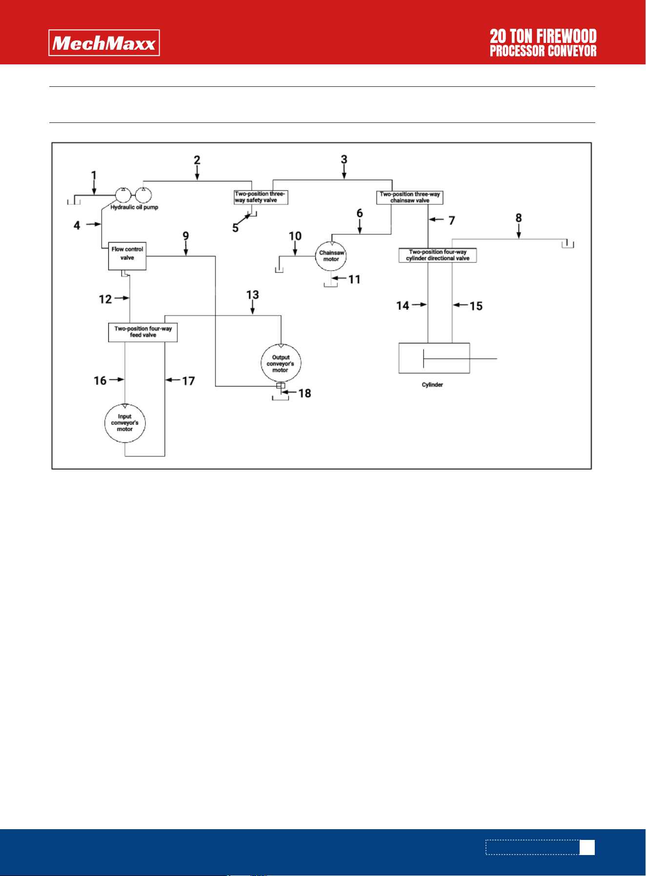
HYDRAULICS DIAGRAM
Hydraulic Hose List
NO.
1
2
3
4
5
6
7
8
9
10
11
12
13
14
15
16
17
18
CONNECTOR INFORMATION
90 degree bend joint M27x1.5
90 degree bend joint M22x1.5
90 degree bend joint M22x1.5
Straight connection M22x1.5
90 degree bend joint, straight connection M22x1.5
90 degree bend joint M22x1.5
90 degree bend joint, straight connection M22x1.5
Straight connection M22x1.5
90 degree bend joint, straight connection M22x1.5
90 degree bend joint, straight connection M18x1.5
Straight connection M27x1.5
90 degree bend joint M22x1.5
90 degree bend joint, straight connection M22x1.5
90 degree bend joint, straight connection M27x1.5
90 degree bend joint, straight connection M27x1.5
90 degree bend joint, straight connection M22x1.5
90 degree bend joint, straight connection M22x1.5
Straight connection M22x1.5
DESCRIPTION
Oil inlet hydraulic hose 5/8"x14"
Safety valve inlet hydraulic hose 1/2"x51"
Chainsaw valve inlet hydraulic hose 1/2"x40"
Flow control valve inlet hydraulic hose 1/2"x16"
Safety valve return hydraulic hose 1/2"x20"
Chainsaw inlet hydraulic hose 1/2"x51"
Cylinder directional valve inlet hydraulic hose 1/2"x16"
Cylinder directional valve return hydraulic hose 1/2"x24"
Flow control valve return hydraulic hose 1/2"x87"
Chainsaw return hydraulic hose 3/8"x43"
Chainsaw return hydraulic hose 1/2"x36"
Feed valve inlet hydraulic hose 1/2"x12"
Output conveyor's motor inlet hydraulic hose 1/2"x6"
Cylinder inlet hydraulic hose 1/2"x33"
Cylinder return hydraulic hose 1/2"x24"
Input conveyor's motor inlet hydraulic hose 1/2"x32"
Input conveyor's motor return hydraulic hose 1/2"x32"
Output conveyor's motor return hydraulic hose 1/2"x36"
35
www.mechmaxx.com
EXPLODED VIEW
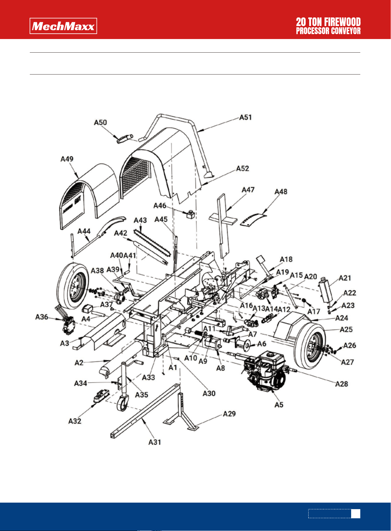
EXPLODED VIEW
MAIN EXPLODED DRAWING

36
www.mechmaxx.com
Main Parts List
EXPLODED VIEW
NO. QTY
A1
A2
A3
A4
A5
A6
A7
A8
A9
A10
A11
A12
A13
A14
A15
A16
A17
A18
A19
A20
A21
A22
A23
A24
A25
A26
A27
A28
A29
A30
A31
1
1
1
1
1
1
1
1
1
1
1
1
1
1
1
1
1
1
1
1
1
1
1
2
2
2
4
1
1
1
1
DESCRIPTION
Main support
Hydraulic cylinder 4"x24"
Safety cover of hydraulic cylinder
Pin of hydraulic cylinder Ø30x6.8"
Engine
Oil pump support
Directly coupling
Hydraulic pump
Oil inlet connection
Feed the oil filter
Swivel bar
The control valve of hydraulic cylinder
The control valve of chainsaw
Motor of chainsaw
Safety valve
Motor support
Chain wheel
Stopper
Stopper sliding rail
Chainsaw restoring lever
Chainsaw lubrication oil tank
Lubrication oil tank switch
Lubrication oil tank connection
Mudguard
Wheel
Self-locking nut M27x1.5
Wheel hub bearing
Wheel axle
Tripod leg
Pin of tripod leg
Towing bar
NO. QTY
A32
A33
A34
A35
A36
A37
A38
A39
A40
A41
A42
A43
A44
A45
A46
A47
A48
A49
A50
A51
A52
1
1
1
1
1
1
2
1
1
1
1
1
1
1
1
1
1
1
1
1
1
DESCRIPTION
Trailer coupler 2"
Trailer pin
Trailer jack support
Trailer jack
The control valve of input conveyor
Battery 12V,3AH
Wheel hub
Cover of hydraulic tank
Adjusting rod
Adjusting rod cover
Chainsaw bar 18"
Chainsaw blade
Wood gripper
Handle of wood gripper
Emergency stop switch
4-way wedge
Wedge adjustment plate
Saw guard
Operating lever sleeve
Handle of chainsaw
Splitter guard
37
www.mechmaxx.com
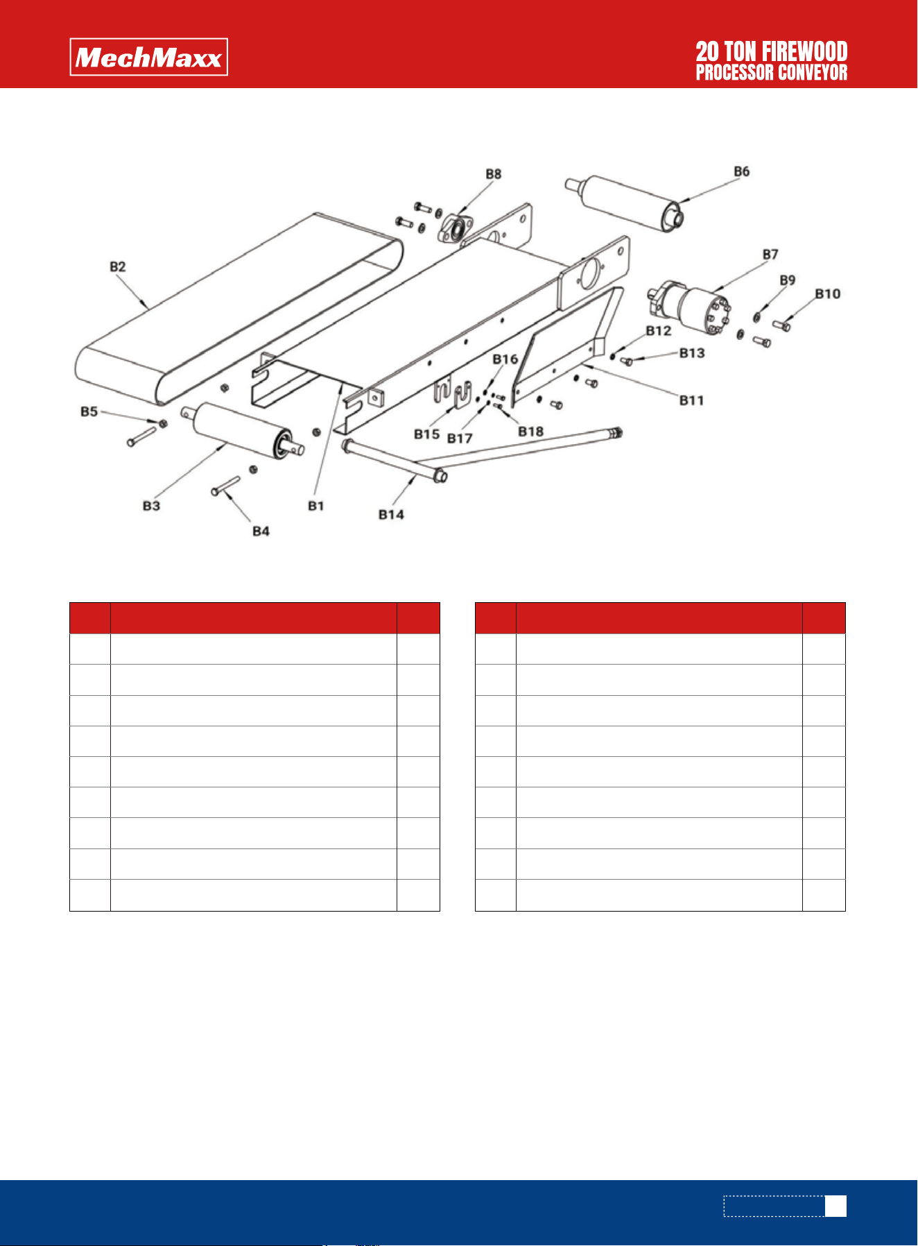
FEED CONVEYOR EXPLODED DRAWING
Feed Conveyor Parts List
EXPLODED VIEW
NO. QTY
B1
B2
B3
B4
B5
B6
B7
B8
B9
1
1
1
2
4
1
1
1
4
DESCRIPTION
Feed rack support
Feed conveyor belt 250X350
Tail pulley weld assy
Adjustable bolt from tail pulley M10x70
Hexagon lock nut M10
Driver pulley weld assy
Hydraulic motor R200
Bearing housing UCFL205
Plain washer Ø12
NO. QTY
B10
B11
B12
B13
B14
B15
B16
B17
B18
4
1
3
3
1
1
1
1
1
DESCRIPTION
Hexagon bolts M12x35
Feed deflecter
Spring washer Ø10x2
Hexagon bolts M10x20
Feed rack support rod
Support plate
Plain washer Ø6
Spring washer Ø6
Hexagon bolts M6x16
38
www.mechmaxx.com
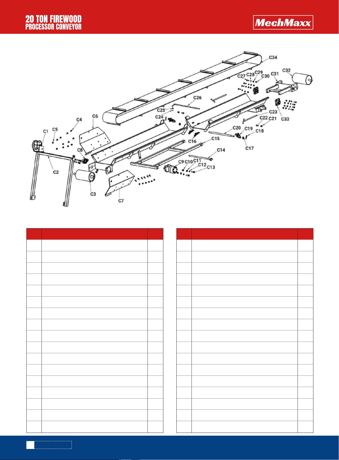
DISCHARGE CONVEYOR EXPLODED DRAWING
Discharge Conveyor Parts List
EXPLODED VIEW
NO. QTY
C1
C2
C3
C4
C5
C6
C7
C8
C9
C10
C11
C12
C13
C14
C15
C16
C17
1
1
2
12
12
1
1
1
1
4
4
4
4
1
1
2
2
DESCRIPTION
Hand winch 1200lbs
Winch support
Driver pulley weld assy
Hex socket flat round head screw M10x20
Self-locking nut M10
Fixing plate left
Fixing plate right
Driver pulley bearing housing UCFL205
Hydraulic motor R200
Hexagon nut M12
Plain washer Ø12
Spring washer Ø12
Hexagon bolts M12x45
Support leg fixed shaft
Support leg
Adjustable buckle
Plain washer Ø16
NO. QTY
C18
C19
C20
C21
C22
C23
C24
C25
C26
C27
C28
C29
C30
C31
C32
C33
C34
2
2
1
2
2
2
1
1
1
8
8
8
8
1
1
2
1
DESCRIPTION
R-pin
Lifting pulley
Support leg shaft
Hexagon bolts M10x30
Hexagon lock nut M10
T adjustable bolts
Split cotter Ø3.2x16
Plain washer Ø10
Conveyor belt support rod
Hexagon bolts M10x35
Spring washer Ø10
Plain washer Ø10
Hexagon nut M10
Tail pulley support
Tail pulley weld assy
Bearing housing UCFU204
Discharge conveyor belt 250X6800