
Operator’s Manual
HYDRAULIC
WOOD
CHIPPER
READ AND UNDERSTAND THE ENTIRE MANUAL BEFORE OPERATING MACHINE


TABLE OF CONTENTS
1
www.mechmaxx.com
TABLE OF CONTENTS
SPECIFICATIONS 2
6
8
14
25
26
30
32
15
17
20
TRANSPORTATION
MAINTENANCE
TROUBLESHOOTING
SAFETY LABELS
GENERAL SAFETY
CONTENTS SUPPLIED
KNOW YOUR MACHINE
ASSEMBLY
OPERATING INSTRUCTIONS
PARTS DIAGRAM

SPECIFICATIONS
2
www.mechmaxx.com
SPECIFICATIONS
Model
Engine Parameter
TX1000
Engine Brand Model
Engine Power
Torque
Fuel Tank Capacity
Max Fuel Consumption
Fuel Type
Air Cleaner
Oil Filter
Recommended Oil
Oil Volume With Filter
Maximum Continuous Working Angle
Cooling Medium
Alternator
Clutch Type
Engine Shaft Diameter
Tensioner
Belt
Zonsen GB1000EI
35HP
74Nm
18L
2.38gal/h
Gasoline 92#
Double filtration
Screw mountiing
SAE 10W-30
2.5L
20°
Forced cooling
25A/300W
Manual clutch
1.125 in
Spring automatic tensioning
2SB1505LE
General Dimensions And Weight
Overall Length-Feed Table Up
Overall Length-Feed Table Down
Overall Width
Overall Height-Discharge Chute Up
Overall Height-Discharge Chute Down
Overall Weight
Tongue Weight
135 in
155 in
55 in
79 in
92 in
1874 lbs
198 lbs

3
www.mechmaxx.com
SPECIFICATIONS
Safety System
Bottom feed stop bar function
Bottom feed stop bar
Bottom feed stop bar diameter
Bottom feed stop bar material thickness
Stop bar resetting Method
Three-position feed control bar
control bar diameter
Control bar material thickness
Control bar position function
Red emergency stop button
Red emergency stop button reset method
Feed roller stopped - reset
Standard
1.2 in
0.07 in
manual reset
Standard
1 in
0.07 in
Forward/stop/reverse
Stop the engine
manual reset
Feed System
Feed Roller Orientation
Feed Roller Nos.
Feed Roller Clamp Load
Knife Nos.
Number Of Feed Roller Motors
Feed Roller Clamping Mechanism Type
Feed Roller Dimension
Minimum Distance From Feed Roller To Blade Housing
Weight Of Feed Roller Assembly
Feed Speed
Infeed Table Height
Infeed Table Length
Infeed Table Width
Infeed Throat Size
Distance From feed roller to end of feed table
Distance From feed table to ground
Horizontal
1
344 lbs
4
1
Spring + feeding roller weight
φ12*11 in
5 in
123 lbs
54ft/min
22 in
24 in
41 in
12*8 in
61 in
30 in

4
www.mechmaxx.com
SPECIFICATIONS
Disc
Bearing Nos.
Bearing hole diameter
Bearing type
Bearing brand
Dynamic capacity
Static capacity
Tensioner
Belt type
2
2 in
Spherical bearing
skf
23.2KN
27KN
Automatic tensioning
Combined belt
Blade Housing parameter
Chipping Capacity
Blade housing width
Cutting disc size
Cutting disc rotating speed
Weight with shaft
Safety lock - number of positions
Blade size
Blade cutting edge Nos.
Blade bolt Nos.
Vertical anvil size
Vertical anvil cutting edge Nos.
Horizontal anvil size
Horizontal anvil cutting edge Nos.
Blade material
Anvil material
Blade holder replaceable
Fan blades Nos.
Fan blade fixation method
Fan blade air flow
8 in
7 in
30*0.7 in
1800
225 lbs
1
4*1*0.5 in
2
3
3.5*7.8*0.5 in
2
3.7*11.6*0.4 in
2
A8 steel
Cr12
No
4
Bolt fixing
92 m
3
/min

5
www.mechmaxx.com
SPECIFICATIONS
Discharge System
Chute height
Flange thickness
Side wall thickness
chute rotation angle
Rotation type
Rotatation lock included?
Rotational lock type
97 in
0.2 in
0.07 in
360°
Manual
Yes
Tighten the dual handle bolts
Hydraulic System
Tank capacity
Recommended oil type
system type
Filtration method
Pump flow at the maximum RPM
Maximum pressure
7.4 Gallon
hm46
open center
Return oil filtration - 10um
4.2gal
2102psi
Electric Control Parameter
System voltage
Battery
Display screen size
Controller Function
Shutdown system
Trailer lights
12V
12V 48AH
4.3 in.
Timer, automatic control, status display, speed display, etc.
Engine
Vehicle power supply
Others
Tow ball size
Hook type
Axle load-bearing capacity
Mud guard
Torque shaft type
Tyre
2" Coupler hitch / 2" ball coupler
ball coupler
2756 lbs torsion shaft
Bolt fixing
Solid torque shaft
φ594x165R13

6
www.mechmaxx.com
SAFETY LABELS
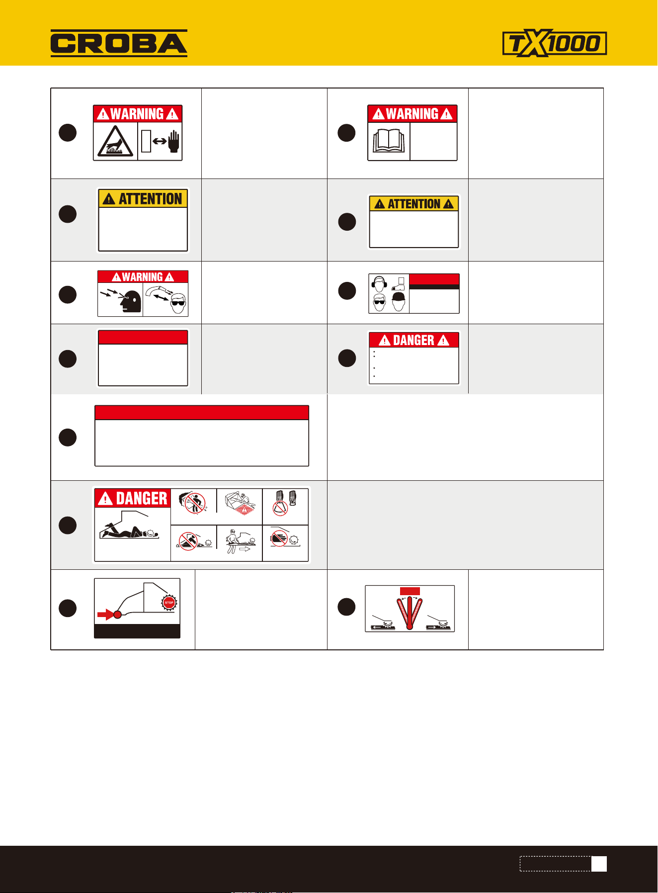
SAFETY LABELS
Safety signs located on the equipment are shown in the illustrations that follow. Good safety requires that you
familiarize yourself with the various safety signs, the type of warning and the area, or particular function related to
that area, that requires your SAFETY AWARENESS.
Safety signs are included in the product decal kit available from your authorized dealer. Decals are not available
separately
Safety Sign Explanations
IMPORTANT!
If parts are replaced that have safety signs on them, new signs must be applied. Safety signs must
always be replaced if they become damaged, are removed, or become illegible.
Before you use the machine,
please read the instruction
manual carefully and pay atten-
tion to the relevant safety infor-
mation.
Before you start the machine,
please read the instruction
manual to avoid hazards result-
ing from improper operation.
Moving belts & spinning blades
inside. Always keep covers in
place while the machine is in
operation.
Please wear safety gear and
heed all safety information.
Stay away from all moving parts
to avoid hazards.
Binding position.
1
3
5
Safety Message
Read Operator's Manual
2
4
6
7
Safety Message
Wear protective
equipment.
Safety Message
Moving parts can crush
fingers.
Close all fields before
starting.
MOVING BELTS &
SPINNING BLADES
INSIDE. ALWAYS KEEP
COVERS IN PLACE
WHILE IN OPERATION
Tie Down
Lube every six months
until grease appears at
headshaft hub.
NOTICE
Lube every six months
until grease appears at
headshaft hub.
7
www.mechmaxx.com
16
17
18
19
1.
5.
6.
7.
2.
3.
4.
Trailer to be level when towing.
Max.towing speed 55 M.P.H.
CAUTION:
TOWING INSTRUCTIONS
TOWING INSTRUCTIONS
Read operator's manual.
Check that hitch & coupler device are rated equal
to or greater than trailer gross weight rating.
Check hitch & coupling device for worn or
defective parts. ensure that coupling device is
secure to vehicle.
Check tires for tread wear & inflation.
Connect safety chains using cross pattern.
connect breakdown chain to bumper or hitch.
Test brakes on both vehicles. check trailer lights
for proper operation.
Inspect & grease bearings every 1000 miles or
once per year.
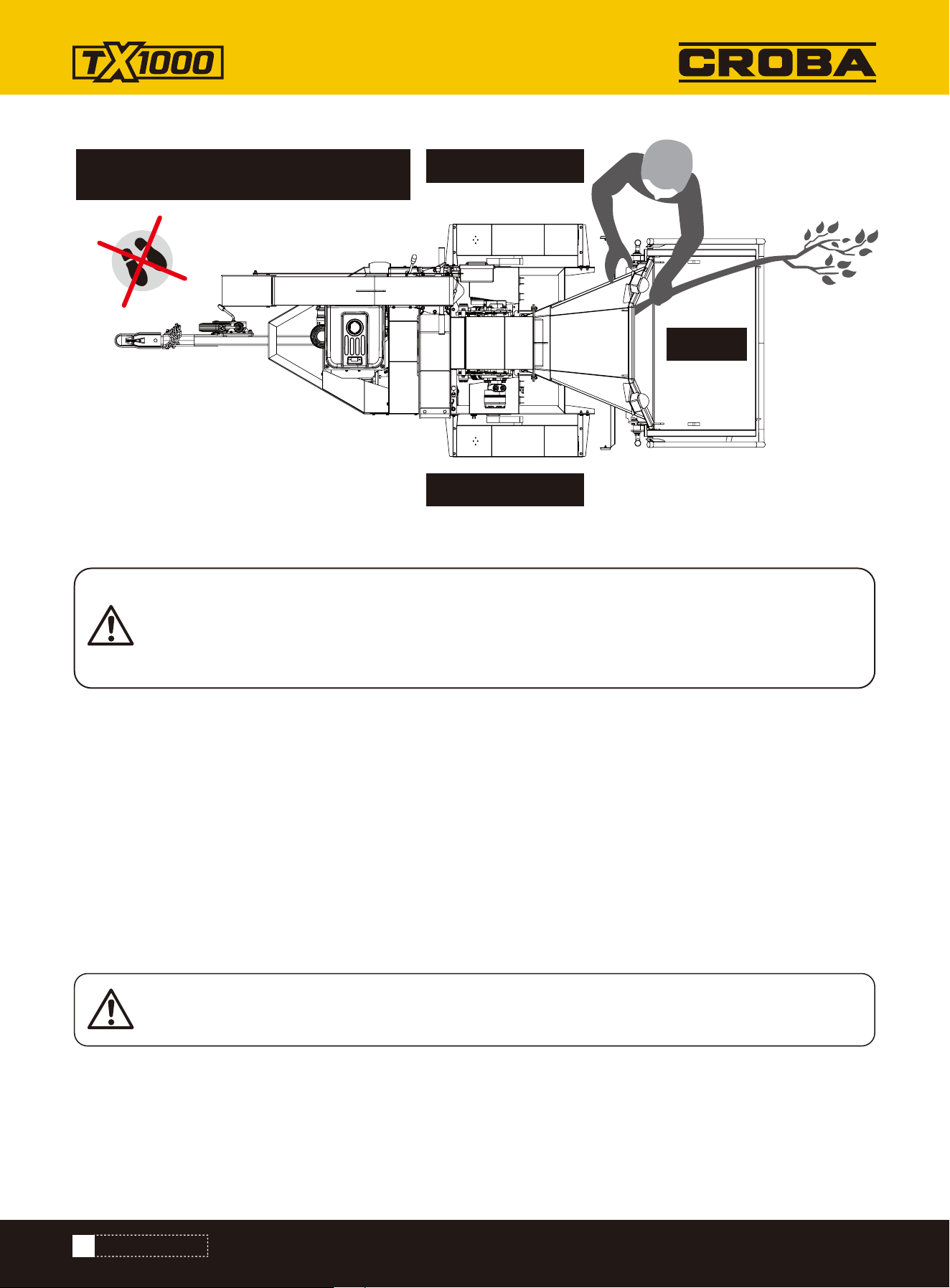
Limbs can snag clothing. Rollers or
blades can grab and pull you in
faster than you can let go of limb.
Cutting injury or death will result.
Feed material only from side of table.
Feed base of limb first.
Never climb onto feed table.
Use wood object to push short material.
Gloves must have
narrow cuffs.
Keep away from
rotating feed rollers
and blades.
PUSH BAR TO STOP FEED
Push bar to stop feed.
Reverse Feed, Stop
Feed, Forward Feed
R F
STOP
Before dragging, please read the instructions careful-
ly to avoid accidents.
Clothing can get snagged on limbs. Rollers or blades
can grab and pull you inwards faster than you can let
go of your limb. Cutting injuries or death may occur.
Moving belts & spinning
blades inside. Always
keep covers in place
while the machine is in
operation.
8
10
11
13
15
12
14
9
Read and understand
Operator's Manual
before using machine.
Read and understand
Operator's Manual
before using machine.
CHECK TIRE CONDITION
AND INFLATION DAILY!
Under-Inflated Tires Can Cause
Unsafe towing conditions, resulting
in roll-over or vehicle accident.
Under-Inflation causes tire damage.
Daily, check your tire
condition and inflation!
Please stay away from
the discharge port and
wear safety gear.
Daily, please check all
fluids.
CHECK ALL
FLUIDS DAILY
USE APPROVED OILS,
LUBRICANTS, COOLANTS
Thrown Chips
Can Blind You
Stay Away
Wear Eye
Protection
NOTICE
Always Wear
Proper personal safety gear and
proper snug-fitting protective
clothing. Loose clothing may
become entangled in moving
machinery causing injury or
death.
Proper personal safety
gear and proper snug-
fitting protective clothing.
Before you use this
product, please read the
safety instructions
carefully.
To prevent damage to alternator DO
NOT operate engine without battery
connected. Disconnect both battery
cable leads when using fast charger or
are working on machine. Connect
battery positive to positive lead and
negative to ground.
To prevent damage to
alternator DO NOT
operate engine without
battery connected.
NOTICE
Never reach inside infeed chute.
Never operate this machine when wearing loose
clothing, scarves, or gauntlet gloves, or gloves with
large cuffs or holes.
Never operate this machine alone.Make certain there
are at least two people with this machine at all times.
Never operate this machine without thoroughly
reading the operator's manual.
SAFETY LABELS

8
www.mechmaxx.com
GENERAL SAFETY
GENERAL SAFETY
Accidents typically occur due to mistakes, lack of training, and failure to follow instructions. It is essential that all
users are properly protected with the appropriate personal protective equipment and receive thorough training. All
users must fully understand the content of this manual and the instructions they need to follow when operating this
machine.
All safety designs have been implemented to safeguard users from all potential injuries during operation and reduce
the risk of accidents. The general safety instructions listed in this document must be adhered to. Disregarding them
could lead to serious injuries, fires, explosions, or even fatalities.
Regarding operator safety, operators should undergo comprehensive training and know the correct way to operate.
Continuously memorizing all instructions and repeatedly reading labels are extremely beneficial.
At no time should children be allowed to operate this machine. Ensure that children, pets, and individuals not using
the equipment remain outside the work area. Stay vigilant and turn off the unit immediately if anyone enters the
work zone. Children must be under the attentive supervision of a responsible adult at all times.
Do not attempt to operate the machine if you are under the influence of drugs, alcohol, or any medication that might
impair your ability to use it correctly.
Dress appropriately for the task. Wear thick, long - legged pants, boots, and gloves. Avoid wearing loose - fitting
clothing, shorts, or any type of jewelry. Fasten long hair so that it is above shoulder length. Keep your hair, clothing,
and gloves clear of the moving parts. Loose items such as clothes, jewelry, or long hair can get caught in the moving
components.
Protect your eyes, face, and head from any objects that the unit might project. Always wear safety goggles or safety
glasses with side shields while operating the machine.
Wear suitable hearing protection. During the machine's operation, it is imperative to keep your hands and feet at a
safe distance from all moving parts. These moving parts have the potential to cut or crush body extremities. Addi-
tionally, always ensure that your hands and feet are clear of any pinch points.
Avoid touching parts that may have become hot due to the machine's operation. Before attempting any mainte-
nance, adjustment, or servicing, allow these parts sufficient time to cool down.
While operating the machine, remain alert, pay close attention to what you are doing, and apply common - sense
principles. Do not overreach as this can lead to loss of balance and potential injury.
Do not operate the machine if you are barefoot, wearing sandals, or other types of lightweight footwear. Instead,
wear protective footwear. Such footwear not only safeguards your feet but also enhances your grip on slippery
surfaces. At all times, maintain proper footing and balance. This will enable you to better control the machine in the
event of unexpected circumstances.
• Operating this wood chipper requires at least two adults. This is an absolute requirement.
• Remove all irrelevant debris from the work site.
• The machine should be located in a safe, open area with good ventilation.
• All bystanders must stay away from the work site, which should be marked with a warning ribbon.
WORKSITE SAFETY
PERSONAL SAFETY

9
www.mechmaxx.com
GENERAL SAFETY
Before starting the machine, conduct a thorough check. Ensure that all guards are in their proper positions and are
functioning correctly. Verify that all nuts, bolts, and similar fasteners are securely tightened.
Under no circumstances should you operate the machine if it requires repair or is in a poor mechanical state.
Replace any damaged, missing, or malfunctioning parts prior to use. Also, inspect for fuel leaks. It is crucial to keep
the machine in a safe working condition at all times.
Do not use the machine if the engine switch fails to turn the machine on or off. Any gasoline-powered machine with
an engine switch that fails to turn the machine on or off poses a significant danger. A faulty switch must be
replaced.
Regularly verify that keys and adjusting wrenches are removed from the vicinity of the machine before starting it. A
wrench or key left attached to a rotating part of the machine can cause serious personal injury.
Take measures to avoid accidental starting. Before transporting the machine or performing any maintenance or
servicing on it, make certain that the engine switch is in the off position. Transporting or working on a machine with
the switch on significantly increases the risk of accidents.
If the machine begins to vibrate abnormally, immediately stop the engine (motor) and check for the cause. Abnor-
mal vibration is typically a warning sign of an underlying problem.
Fuel is extremely flammable, and its vapors have the potential to explode upon ignition. It is essential to take appro-
priate precautions when handling fuel to minimize the risk of severe personal injury.
When refilling or draining the fuel tank, use only an approved fuel storage container and perform the task in a clean,
well-ventilated outdoor location. Under no circumstances should you smoke, or permit sparks, open flames, or any
other ignition sources to be present in the vicinity while adding fuel or operating the machine.
Never fill the fuel tank indoors. Keep grounded conductive objects like tools away from exposed, live electrical
components and connections to prevent sparking or arcing, as these phenomena could ignite fuel fumes or vapors.
Always shut off the engine and allow it to cool down completely before refilling the fuel tank. Never remove the fuel
tank cap or add fuel when the engine is running or still hot. Do not operate the machine if there are known leaks in
the fuel system.
Loosen the fuel tank cap slowly to release any pressure within the tank. Do not overfill the fuel tank; fill it to a level
no higher than 1/2" below the bottom of the filler neck to accommodate fuel expansion caused by the heat of the
engine.
Avoid creating any potential ignition sources for spilled fuel. If fuel is spilled, do not try to start the engine. Instead,
move the machine away from the spill area and refrain from creating any ignition sources until the fuel vapors have
completely dissipated.
If fuel comes into contact with your skin or clothes, wash your skin immediately and change your clothes. Store fuel
only in containers that are specifically designed and approved for this purpose.
Store fuel in a cool, well-ventilated area, keeping it safely away from sparks, open flames, or other ignition sources.
Never store fuel or a machine with fuel in the tank inside a building where fuel fumes could reach a spark, open
flame, or any other ignition source, such as a water heater, furnace, or clothes dryer. Allow the engine to cool down
before storing the machine in any enclosed space.
INSPECT YOUR MACHINE
FUEL SAFETY

10
www.mechmaxx.com
GENERAL SAFETY
When using the machine, it is crucial to adhere to the following material - feeding guidelines for optimal perfor-
mance and longevity.
Only feed clean materials into the machine. Foreign substances like soil, sand, grit, stones, and metal pieces can
severely damage the sharp edges of the cutting knives. Additionally, root balls and dead wood will rapidly dull the
blades.
Steer clear of feeding pine needles, flax, and cabbage tree leaves into the machine. These stringy materials have a
tendency to wrap around the rotor shaft and gradually work their way into the bearing, causing potential mechanical
issues.
Avoid inserting short, stubby pieces of wood into the machine. Such pieces often bounce and spin erratically within
the feed hopper. Instead, combine these short pieces with longer ones before feeding. Once you've become
acquainted with the machine's capabilities, prune materials to match its requirements.
This machine is designed to be self-feeding. Under no circumstances should you force branches into the blades. Let
the machine automatically draw in the materials. Before adding the next batch of branches, allow sufficient time for
the machine to reach its maximum spinning revolutions. This ensures efficient operation and reduces the risk of
jams or damage to the equipment.
FEEDING MATERIALS
GENERAL SAFETY MATTERS
This wood chipper is equipped with a Tow Bar with a 2-inch Coupler. However, never attempt to tow the machine on
public highways, roads, or arterial roads. Towing this equipment on these public routes not only violates the traffic
regulations in most regions but also poses a serious safety risk.
MOVING SAFETY
MACHINE USE AND CARE
Position the machine in such a way that it cannot move during maintenance, cleaning, adjustment, assembly of accesso-
ries or spare parts, as well as under storage.
• Always stop the chipper engine before making any adjustments, refuelling or cleaning.
• Always check the rotor has stopped rotating and remove the chipper ignition key before maintenance of any kind,
orwhenever the machine is to be left unattended. If in doubt, look through the in-feed funnel to see if rotor is still
moving.
• Always check the machine is well supported and cannot move. If working on an incline, position on solid ground,across
the slope.
• Always operate the chipper with the engine set to maximum speed when chipping.
• Always check (visually) for fluid leaks. If found, resolve the leak before operating the chipper.
• Always take regular breaks. Wearing personal protective equipment for long periods can be tiring and hot.
• Always keep hands, feet and clothing out of feed opening, discharge and moving parts.
• Always use a push stick to push in short pieces. Under no circumstances should you reach into the funnel.
• Always keep the operating area clear of people, animals and children.
• Always keep the operating area clear from debris build up.
• Always keep clear of the chip discharge tube. Foreign objects may be ejected with great force.
• Always ensure protective guarding is in place before commencing work. Failure to do so may result in personal injury
or loss of life.
• Always operate the chipper in a well ventilated area - exhaust fumes are dangerous.
• Ensure a fire extinguisher is available on site.
• Ensure a personal first aid kit and hand cleaning materials are available (e.g. waterless skin cleanser).
• Always cover ignition switch with plug provided when towing or jet wash cleaning.

11
www.mechmaxx.com
GENERAL SAFETY
MAINTAINING SAFETY
Do not force the machine. Use the correct machine for your application. The correct machine will do the job better and
safer at the rate for which it is designed.
Do not change the engine governor settings or over-speed the engine. The governor controls the maximum safe operating
speed of the engine.
Do not run the engine at a high speed when you are not working.
Do not put hands or feet near rotating parts.
This machine has two rotating cutting knives capable of amputating hands and feet and throwing objects. Keep hands
and feet out of openings while machine is running. Failure to observe these safety instructions could result in serious
injury or death.
Avoid contact with hot fuel, oil, exhaust fumes and hot surfaces. Do not touch the engine or muffler. These parts get
extremely hot from operation. They remain hot for a short time after you turn off the unit. Allow the engine to cool before
doing maintenance or making adjustments.
If the machine should start to make an unusual noise or vibration, immediately shut off the engine, disconnect the spark
plug wire, and check for the cause. Unusual noise or vibration is generally a warning of trouble.
Use only attachments and accessories approved by the manufacturer. Failure to do so can result in personal injury.
Keep the engine and muffler free of grass, leaves, excessive grease or carbon build up to reduce the chance of a fire
hazard.
Never douse or squirt the unit with water or any other liquid. Keep handles dry, clean and free from debris. Clean after each
use.
Observe proper disposal laws and regulations for gas, oil, etc. to protect the environment.
When storing machine out of the reach of children and do not allow persons unfamiliar with the machine or these instruc-
tions to operate it. This machine can be dangerous when used by an untrained user.
Some parts of this machine are made of plastic or rubber and should be kept away from any chemicals. Always remember
never to cover the machine while the muffler is still hot. Do not alter or adjust any part of the chipper shredder or its
engine that are sealed by the manufacturer or distributor. Only a qualified service technician may adjust parts that
increase or decrease governed engine speed. To maintain your machine, check for any misalignment or binding of any
moving parts. Parts that are broken or worn down may affect the machine's operation. If damaged or worn parts are
identified, they should be repaired before use. Many accidents are caused by poorly maintained equipment.
• Maintain a safety exclusion zone around the chipper of at least 10 meters (approximately 33 feet) for the general
public or employees without adequate protection. Use hazard tape to identify this working area and keep it clear from
debris build up. Chips should be ejected away from any area the general public have access to.
• Hazardous material - Some species of trees and bushes are poisonous. The chipping action can produce vapour, spray
and dust that can irritate the skin. This may lead to respiratory problems or even cause serious poisoning. Check the
material to be chipped before you start. Avoid confined spaces and use a face mask if necessary.
• Be aware when the chipper is processing material that is an awkward shape. The material can move from side to side
in the funnel with great force. If the material extends beyond the funnel, the brash may push you to one side causing
danger. Badly twisted brash should be trimmed before being chipped to avoid thrashing in the feed funnel.
• Be aware that the chipper can eject chips out of the feed funnel with considerable force. Always wear full head and face
protection.
• Always work on the side of the machine furthest from any local danger, e.g., not the road side.
• Never leave the chipper unattended when running. Machines must be supervised at all times when in use.
• In the event of an accident, stop the machine, remove the key and call the emergency services immediately.
The operator should be aware of the following points:
BASIC WOOD CHIPPING SAFETY
12
www.mechmaxx.com
GENERAL SAFETY
Burn Hazard! The battery electrolyte is highly corrosive and poisonous. Any contact with the eyes, skin,
or clothing can cause severe burns and other grave personal injuries. In case of contact, seek immedi-
ate medical assistance without delay. Exercise extreme caution when handling batteries to prevent
electrolyte leakage and potential exposure.
Danger: Keep the discharge chute clear of
all personnel during wood chipping.
Risk of explosion or fire! Do not let metal objects come into contact with the battery terminals. Arcing can
cause a fire or explosion. Cover terminals if working near batteries.
BATTERY SAFETY
- Wear gloves and safety glasses or a face shield when working on or near batteries.
- Use a battery carrier to lift the battery or place hands at opposite corners to avoid spilling acid through the vents.
- Avoid contact with battery electrolytes:
• External Contact: Flush immediately with water.
• Eye Contact: Flush with water for 15 minutes. Get prompt medical attention. Clean up any spilled electrolyte immedi-
ately.
• Avoid contact with battery posts, terminals and related accessories. They contain lead and lead compound chemicals
known to cause harm if ingested. Wash hands immediately after handling battery.
• Keep all sparks and flames away from batteries. Electrolyte fumes are explosive.
• To avoid injury from spark or short circuit, disconnect battery ground cable before servicing any part of the electrical
system.
• Do not jump-start or charge a frozen battery. Frozen batteries can explode and result in death or serious injury. Let the
battery thaw before charging.
OPERATE ZONE
OPERATE ZONE
INFEED

13
www.mechmaxx.com
HYDRAULIC SAFETY
• Ensure all components in the hydraulic system are clean and well-maintained.
• Before pressurizing the system, verify that all fittings are secure and that lines, hoses, and couplings are free from
damage.
• Do not attempt temporary or makeshift repairs on hydraulic lines, fittings, or hoses using tape, clamps, or adhesives.
Hydraulic systems operate under extremely high pressure, and such repairs can suddenly fail, posing serious safety
hazards.
• Always wear appropriate hand and eye protection when inspecting for high-pressure leaks. Use a piece of wood or
cardboard—never your hands—to help detect and isolate the source of a leak safely.
• If you are injured by a high-pressure stream of hydraulic fluid, seek immediate medical attention. Even small punctures
can lead to serious infections or toxic reactions.
• Always relieve system pressure before performing any maintenance or repair work.
GENERAL SAFETY
14
www.mechmaxx.com
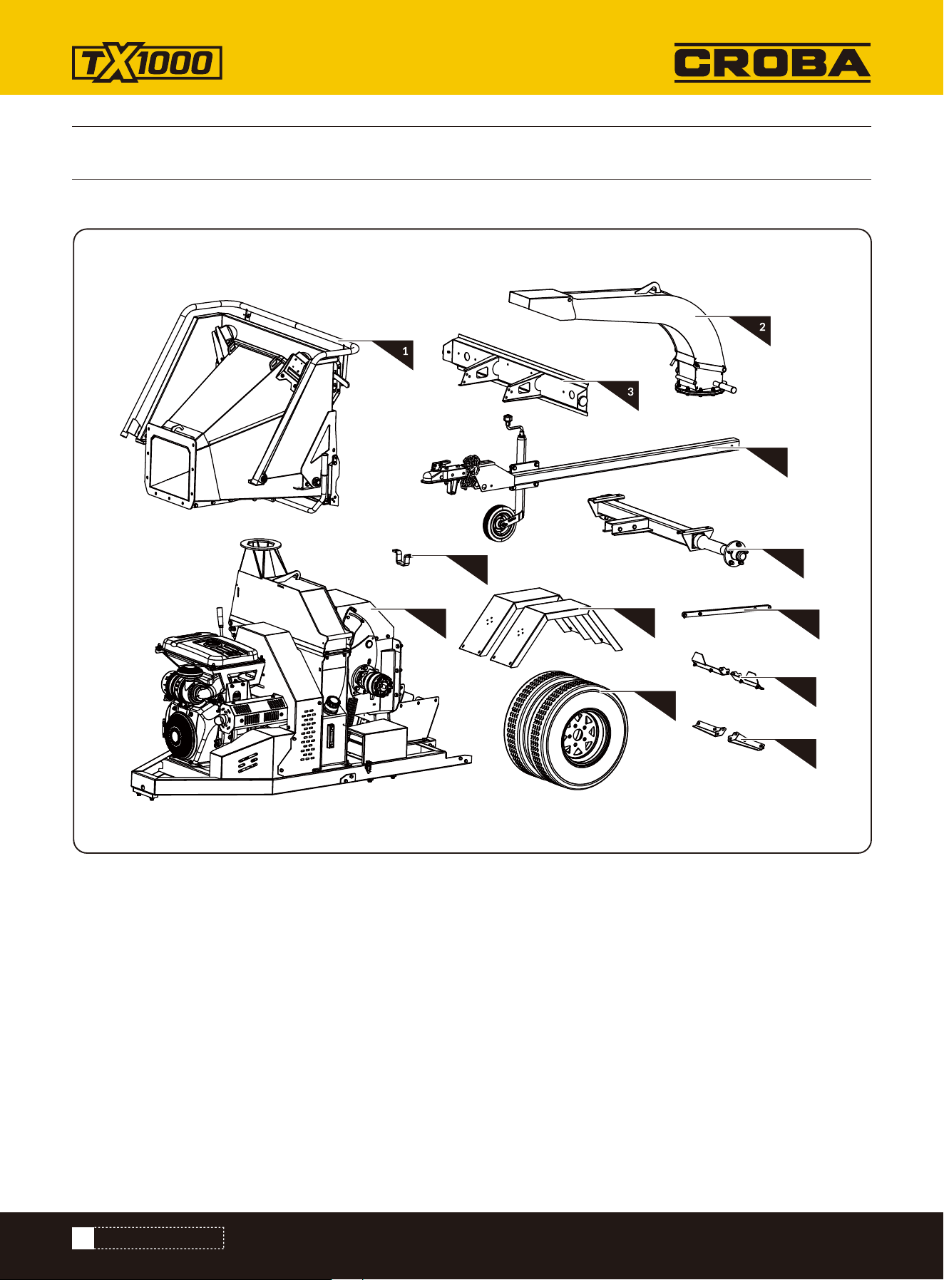
1. In-feeding chute
2. Lower discharging chute
3. Taillight holder
4. Tow Bar and Jockey Wheel
5. Reinforced
6. Axle
7. Engine and base frame
8. Fender
9. Connecting rod
10. Wheels
11. Fender assembly
12. Fender assembly
Your Wood chipper comes partially assembled and contains the following:
4
6
9
11
12
5
7
8
10
CONTENTS SUPPLIED
CONTENTS SUPPLIED
15
www.mechmaxx.com
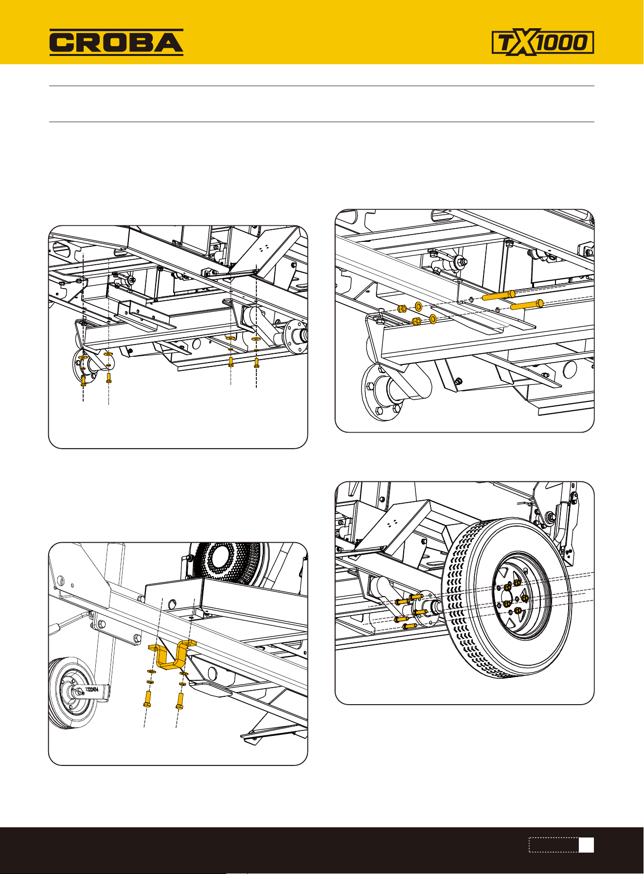
ASSEMBLY
ASSEMBLY
Following the assembly directions below, you will assemble the machine in a few minutes.
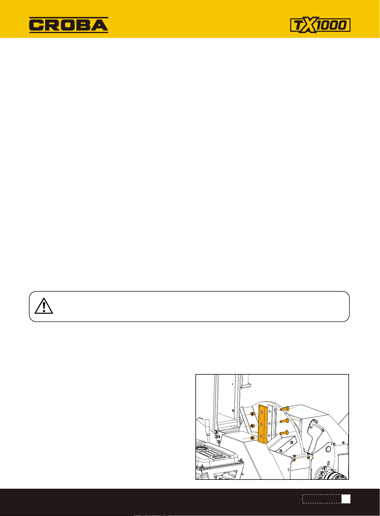
Install the axle onto the base frame and secure it using
M12×30 full-thread hex head bolts, 12 mm spring
washers, and 12 mm flat washers.
AXLE
Assemble the wheel onto the axle.
WHEELS
Begin by securing the tow bar and jockey wheel using
the tow bar clamp. Use M12×35 full-thread hex head
bolts, along with 12 mm flat washers and 12 mm spring
washers.
Next, attach the tow bar and jockey wheel to the base
frame using M12×90 hex head bolts, M12 hex lock nuts,
and 12 mm flat washers.
TOW BAR AND JOCKEY WHEEL
16
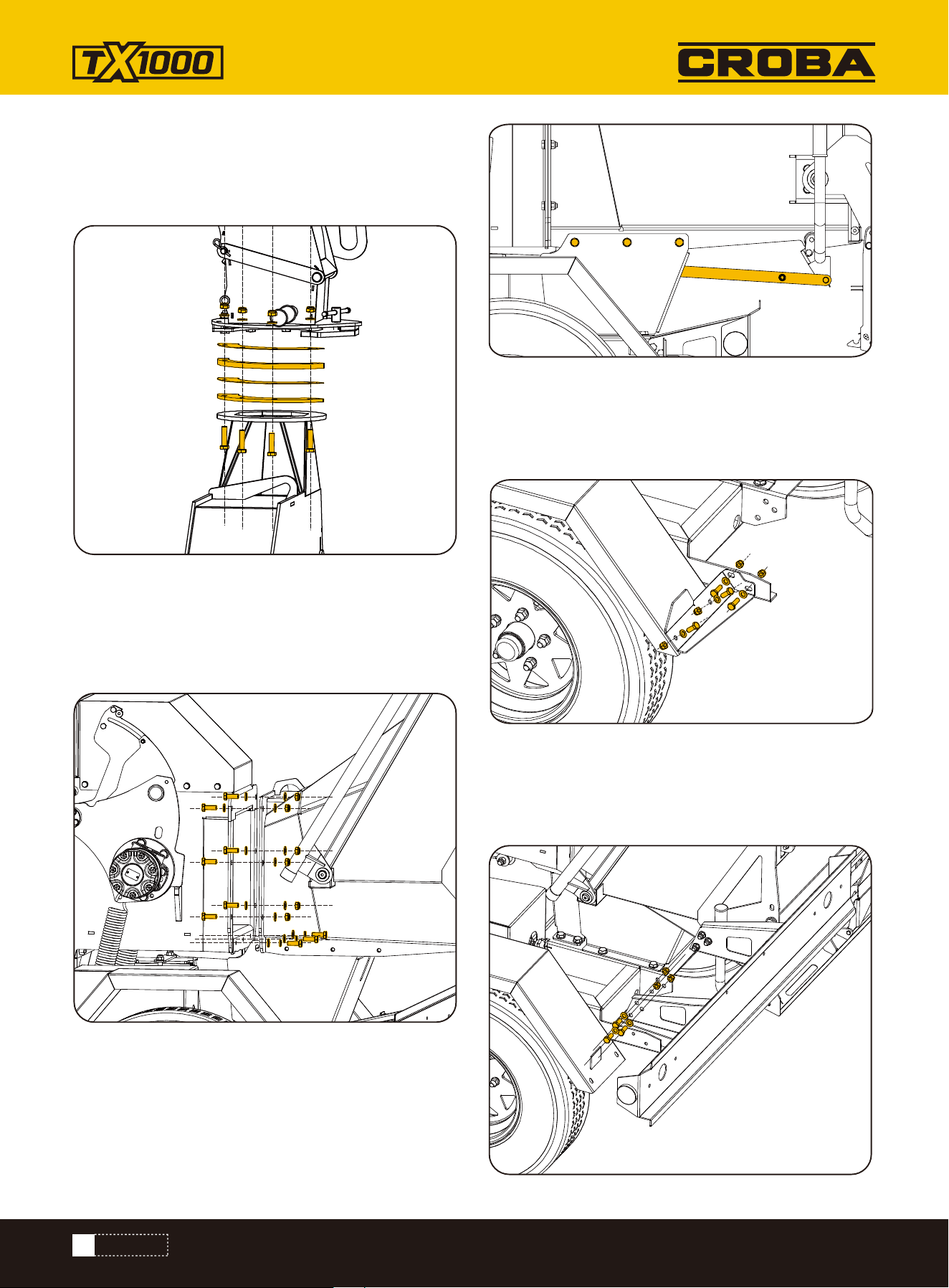
www.mechmaxx.com
Use M10×40 full-thread bolts, M10 hex jam nuts, and 10
mm flat washers to assemble the lower discharging
chute to the base frame.
Assemble the in-feeding chute to the base frame using a
thin hexagon lock nut M10, a full - thread hexagon - head
bolt M10×30, a plain washer Class C 10 and a spring
washer 10.
Assemble the fender to the base frame through the
fender assembly using an M8×20 full-thread hexagon
head bolt, M8 hex lock nut, and Ø8 plain washer.
Then use a full - thread hexagon - head bolt M10×25, a
spring washer 10 and a plain washer Class C 10 for
fixation.
Fix both ends of the connecting rod to the positions
shown in the figure using a pin of Type B 8×26, a plain
washer 8 and a split pin 2×20.
LOWER DISCHARGING CHUTE
IN-FEEDING CHUTE
FENDER
Use a full-thread M10×25 hexagon head bolt, a Class C
M10 plain washer, and an M10 hexagon lock nut to
assemble the taillight holder to the base frame.
TAILLIGHT HOLDER
ASSEMBLY
17
www.mechmaxx.com
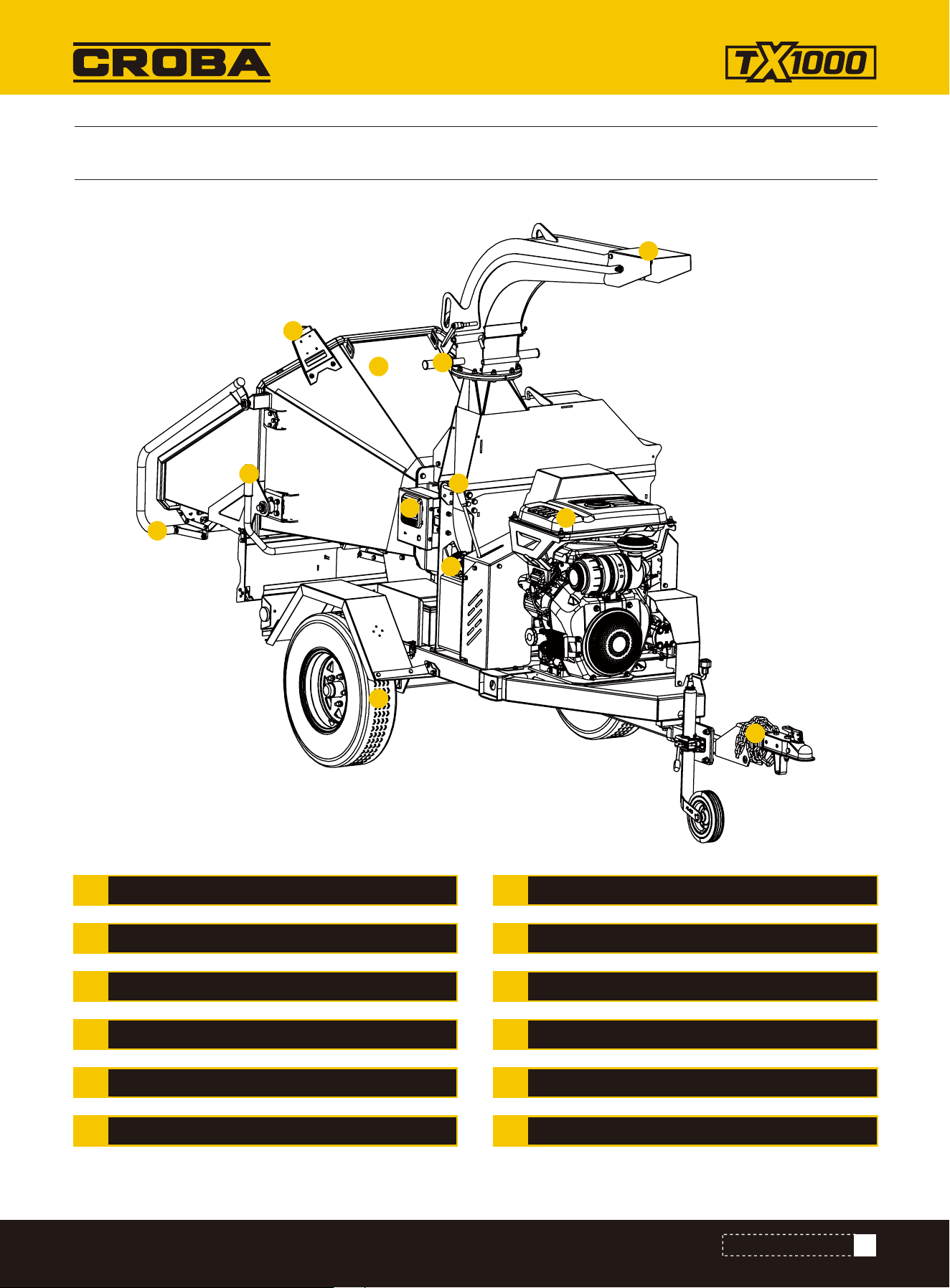
KNOW YOUR MACHINE
KNOW YOUR MACHINE
FEED CHUTE
DEFLECTOR
DIRECTION HANDLE
BELT CLUTCH HANDLE
ENGINE
TOW COUPLER
HYDRAULIC RETURN PORT
WHEEL
FEED ROLLER REVERSING LEVER
FEED CONTROL LEVER
CONTROL PANEL
EMERGENCY STOPA
B
C
D
E
F
G
H
I
J
K
L
A
B
C
E
F
D
K
L
J
H
G
I
18
www.mechmaxx.com
KNOW YOUR MACHINE
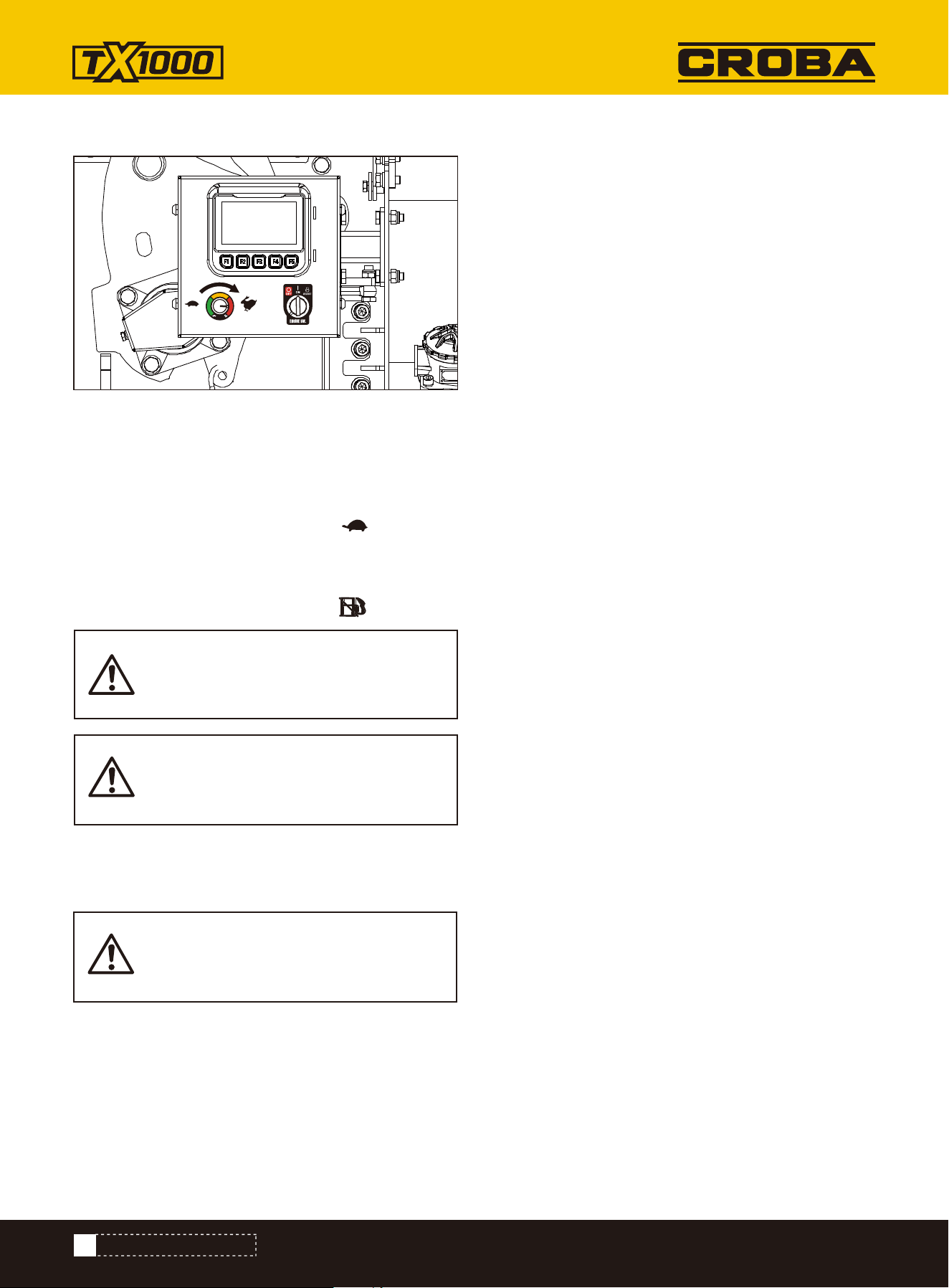
In case of an emergency, press the emergency stop
button to immediately halt the machine, including the
engine.
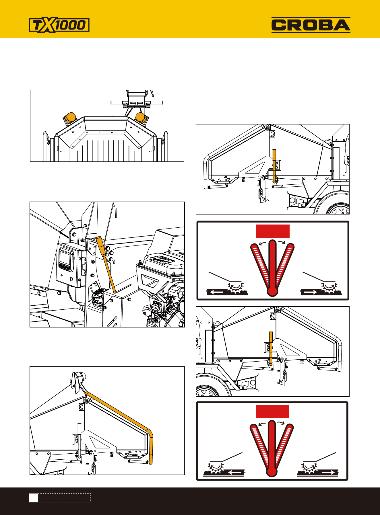
The control lever has three positions, as shown in the
figure:
Left: The feed roller rotates in reverse to discharge
material.
Center: Both feeding and reversing are stopped.
Right: The feed roller rotates forward to start feeding.
After starting the engine, pull the belt clutch lever to the
position shown in the figure.
EMERGENCY STOP
BELT CLUTCH HANDLE
When the feed control lever is pressed, feeding stops.
Pulling it up resumes feeding.
FEED ROLLER REVERSING LEVER
FEED CONTROL LEVER
R F
STOP
F R
STOP

19
www.mechmaxx.com
KNOW YOUR MACHINE
The flow control valve has 10 scale positions, marked 0
to 9.
• Turning the dial counterclockwise increases the
number, allowing greater flow and resulting in faster
feed roller speed.
• Turning it clockwise decreases the number, allowing
less flow and resulting in slower feed roller speed.
The flow control valve adjusts the speed of the hydrau-
lic motor that drives the feed rollers.
• When processing larger-diameter branches, reduce
the flow as needed.
• When processing smaller-diameter branches,
increase the flow to raise the feed speed.
Display Parameters
• Display Size: 4.3-inch true color screen.
• Resolution: 800 × 480 pixels.
1.Battery Voltage (Charging Status)
2.Engine Working Hours
3.Engine Oil Pressure Alarm
4.Feed / Reverse Status Indicator
5.Chipper Disc Speed Display
6.Alarm Message Prompt:
• Example: Emergency stop is activated. Engine cannot
start. Please release the emergency stop button.
High Speed: Sets the automatic feed start speed.
Default: 1750 rpm
Low Speed: Sets the automatic feed stop speed.
Default: 1500 rpm
Cal.: Calibration parameter for the speed sensor.
Default: 8
Back Time: Set reverse feed time. Default: 0 seconds
Reserved Blank: Reserved space for future use
Restore Defaults: Reset parameters to factory default
values
• Home
• Settings
• Confirm
• Up (Increase)
• Down (Decrease)
Button Function Area:
Indicates the function of each button based on the
current screen. The functions are as follows:
System Settings Interface
Press the Settings button on the main screen
to enter the settings interface.
The main interface primarily displays key information
such as alarm icons, analog gauges, text-based alarm
messages, operating status, and total working time.
Details are as follows:
HYDRAULIC FLOW CONTROL VALVE
CONTROL PANEL
1 2
3 4
5
6

20
www.mechmaxx.com
All personnel involved with this machine must thoroughly read and fully understand the contents of this manual.
Prior to use, training is essential and should be provided by the dealer. The dealer must also possess a comprehen-
sive understanding of the manual, including proper operation, maintenance, and all aspects related to the machine’s
functions and safety protocols.
Work Site Preparation:
•
Remove all rocks, metal objects, or other materials that could damage the machine from the work area and mate-
rial storage zones.
•
Clear all obstacles that may block walkways or access paths.
•
Ensure the work site is not located under high-voltage power cables.
•
Verify the work site is well-lit and adequately ventilated.
•
Confirm the work site is in an open area with sufficient space for operation and movement.
•
Identify where branches/twigs will be processed and designate a collection area for wood chips.
•
Maintain enough space for material delivery and unobstructed access.
•
Check that first aid kits are fully stocked, in good condition, and readily accessible.
•
Ensure at least two adult operators are present during machine operation to monitor functionality and maintain
site safety.
Material Preparation:
Proper material preparation enhances efficiency, improves working conditions, and reduces the risk of unnecessary
maintenance costs.
Chipper Preparation:
To secure the machine on-site, one of the following methods must be used:
•
Proper towing and anchoring to prevent unintended movement; or
•
Deployment of support wheels with wheel chocks (blocks) firmly in place to stabilize the unit.
Note: Operating the chipper on uneven, sloped, or unstable ground can result in equipment instability and poses
serious safety risks.
•
An inclined feeding end facilitates easier material loading.
•
Ensure materials are sufficiently long (over 1.2m) to keep hands clear of the rollers. Short materials can be pushed
into the rollers using longer pieces as a guide.
•
Adjusting material weight and length by cutting them into appropriate pieces can reduce the risk of operator
injury.
•
This chipper is designed for processing branches free of foreign objects such as rocks, metals, mud, or any
substances that could damage the machine.
PREPARATION
Metals, rocks, glass, or similar substances can severely damage the machine, leading to property loss,
injuries, or even fatalities. Vines or entanglement wrapping around twigs may entangle operators or
damage the machine, so all vines in the material must be removed beforehand.
OPERATING INSTRUCTIONS
OPERATING INSTRUCTIONS
21
www.mechmaxx.com
OPERATING INSTRUCTIONS
While Towing:
When towing the chipper, follow these safety precautions to ensure secure transportation:
•
Ensure the towing vehicle is powerful enough to handle the chipper’s weight.
•
Always park the vehicle on flat, level ground before connecting or disconnecting the chipper.
•
The towing vehicle must be fully stopped with the parking brake engaged.
•
Never operate the chipper while it is being transported.
•
Ensure the tow coupler is securely fixed onto the vehicle's tow ball.
•
Attach the safety chain and cable:
•
The chain must be evenly hooked and must not drag on the ground.
•
The cable must be correctly connected.
•
Check that all trailer lights (brake, indicator, etc.) are functioning properly.
When Parking Without Towing:
•
Each model is equipped with a jacky wheel for support when parked without being towed. Always retract the jacky
wheel during transportation.
•
Ensure the chipper’s chassis remains parallel to the ground.
•
Place wheel blockers in position to secure the wheels.
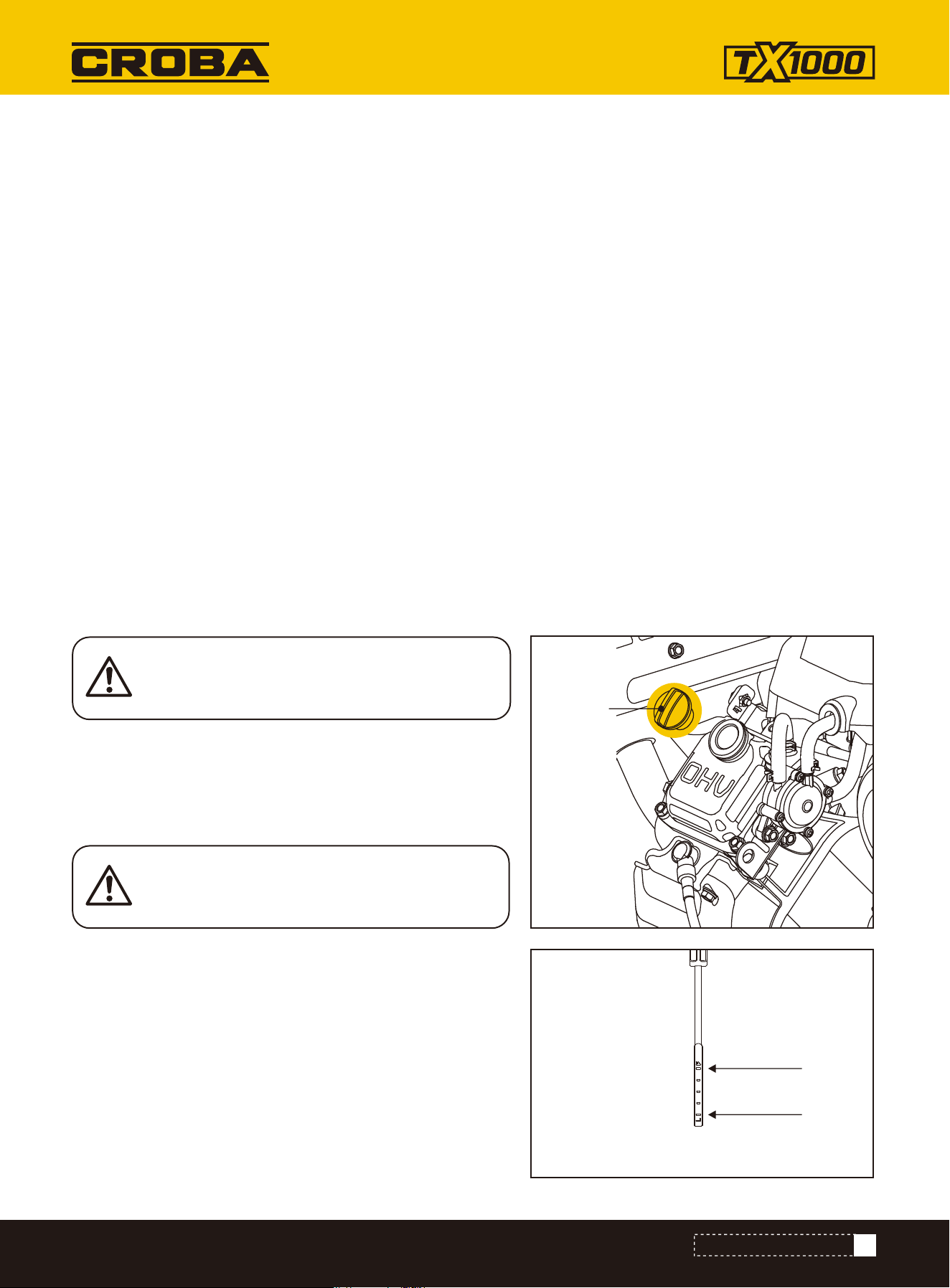
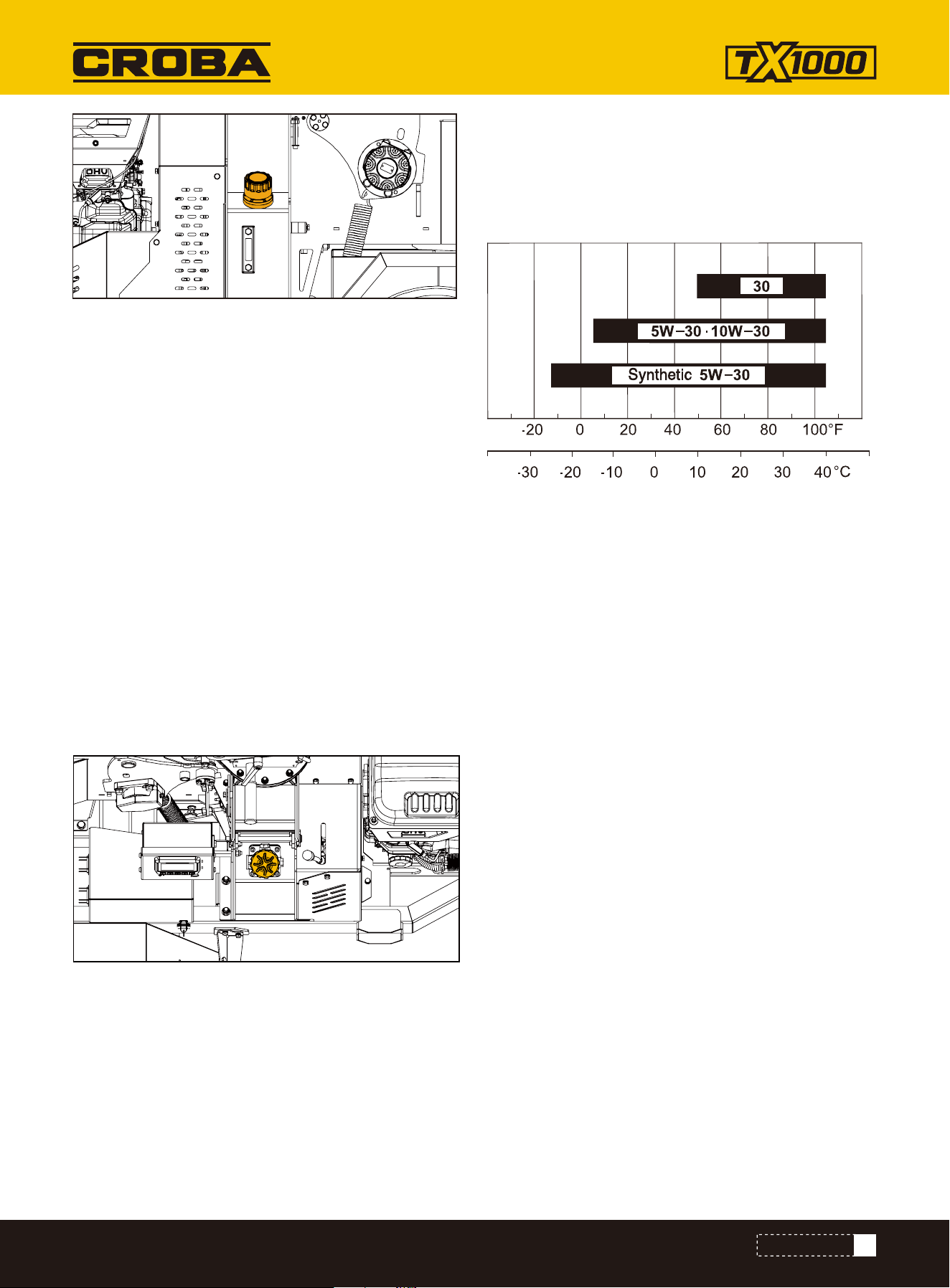
1. Make sure the chipper shredder is on a flat, level surface.
2. Remove the oil fill cap/ dipstick to add oil.
3. Remove the dipstick and check the oil filling volume which
should be at the upper limit of the scale (F point).
4. Completely insert the dipstick into the dipstick hole during
inspection.
5. Dispose of used oil at an approved waste management
facility.
SAE 10W-30 is recommended for general, all-temperature use.
Other viscosities shown in the chart may be used when the
average temperature in your area is within the indicated range.
(See engine manual for oil capacity, oil recommendation, and
location of fill cap.).
ADD OIL TO ENGINE
*Shipped with NO fluids. Must add own fluid
Engine oil
Oil plug
Oil level gauge
Upper limit(F)
Lower limit(L)
The engine is shipped without oil. Do not start
the engine before adding oil.
DO NOT OVERFILL. Check engine oil level daily
and add as needed.
22
www.mechmaxx.com
OPERATING INSTRUCTIONS
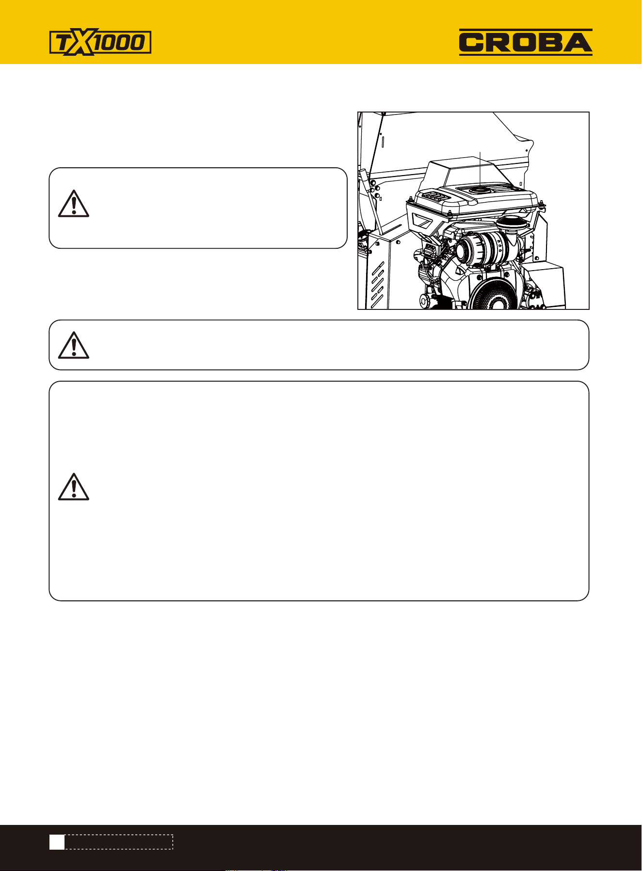
With the engine stopped, check the fuel level gauge. Refill the
fuel tank if necessary.
Use clean, fresh, regular unleaded gasoline. DO NOT mix oil
with gasoline. Be sure not to fill above the upper limit mark.
Always allow room for fuel expansion.
NEVER use engine or carburetor cleaner products in the fuel tank or permanent damage may occur.
*Shipped with NO fluids. Must add own fluid
ENGINE FUEL
Fuel filler
Pressure can build up in the fuel tank. Allow the
engine to cool for at least two minutes before
removing fuel cap. Loosen the fuel cap slowly to
relieve any pressure in the tank.
Do not fill the fuel tank above the upper limit. Over fill will results in engine die or damage the carbon
canister (if equipped) and void your warranty.
Gasoline is highly flammable and extremely explosive.
Fire or explosion can cause severe burns or death.
Keep flammable items away while handling gasoline.
Fill fuel tank outdoors and in a well-ventilated area with the engine stopped.
Always wipe off spilled fuel and wait until the fuel has dried before starting the engine.
DO NOT operate the engine with known leaks in the fuel system.
Use proper fuel storage and handling procedures. DO NOT store fuel or other flammable materials
nearby.
Empty the fuel tank before storing or transporting this engine.
Keep fire extinguisher handy and be prepared if a fire starts.
FIRE OR EXPLOSION
23
www.mechmaxx.com
OPERATING INSTRUCTIONS
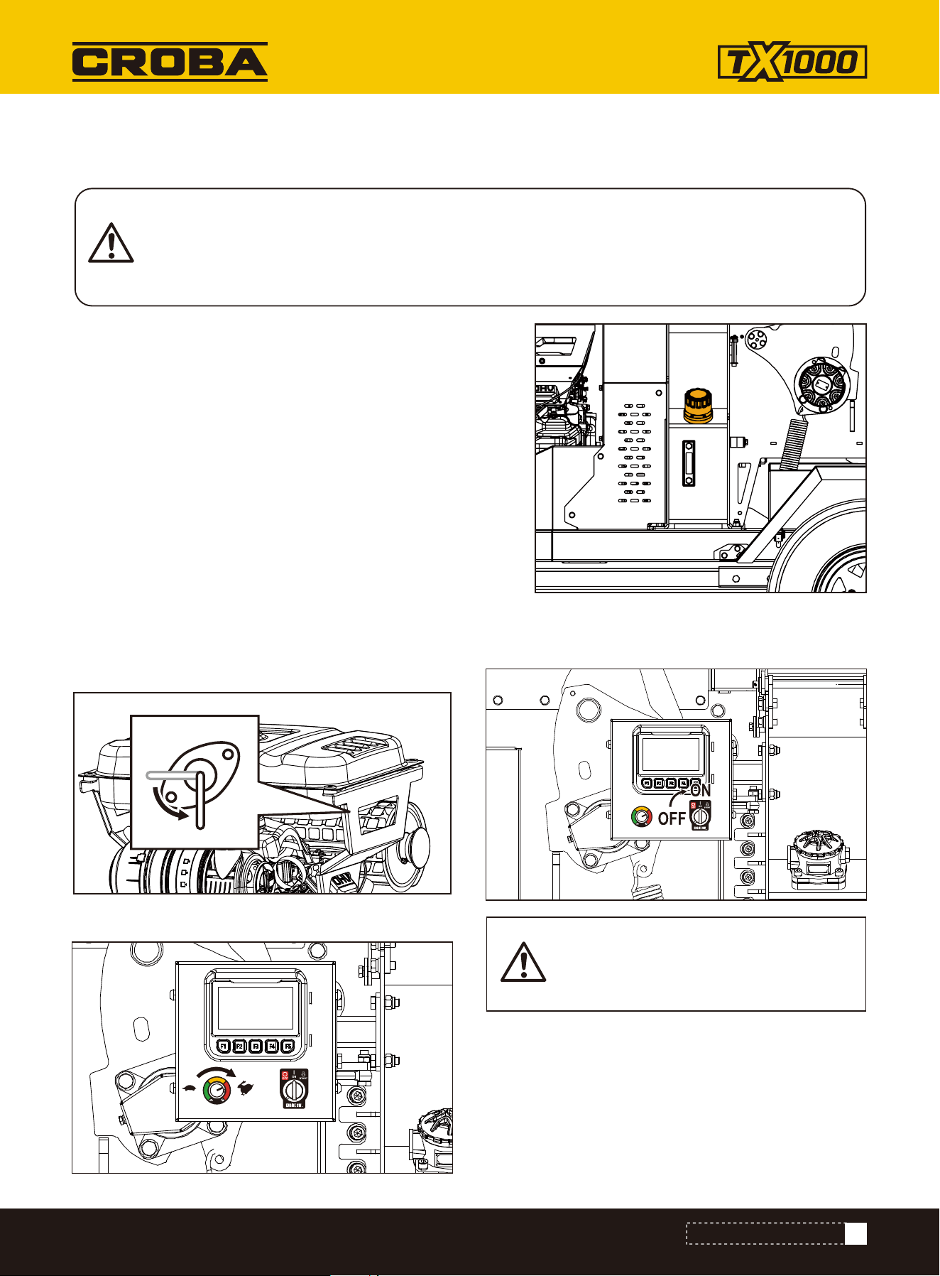
1. Remove the black screw cap from the top of the filter housing.
2. Partially remove filter element from inner cup.Leave filter to
drain for 15 minutes.
3. Remove filter element from cup when clear of hydraulic oil.
4. Remove drain plug and drain oil into a suitable container.
5.Replace drain plug.
6.Refill with ISO VG 46 hydraulic oil until the level is between the
min and max lines on the tank (about 15 litres).
7.Refit the filter cup, install a new filter element and refit the
black screw cap, to the filter housing, ensuring o-ring remains in
place.
*Shipped with NO fluids. Must add own fluid
HYDRAULIC OIL
STARTING ENGINE
USE PLASTIC GLOVES TO KEEP OIL OFF SKIN AND DISPOSE OF THE USED OIL AND FILTER IN AN
ECOLOGICALLY SOUND WAY. THE OIL AND FILTER SHOULD BE CHANGED ONCE A YEAR OR AT ANY
TIME IT BECOMES CONTAMINATED. BEFORE STARTING CHECK THAT THE CHIPPER IS STANDING
LEVEL AND BRUSH AWAY LOOSE CHIPS.
When starting the machine for the first
time, you need to start it several times
when starting the key.
1. Open the fuel valve (fuel pipe switch) under the
fuel tank.
3. Move the engine switch to the ON position.
2. Move the throttle slightly.
ON
OFF
24
www.mechmaxx.com
OPERATING INSTRUCTIONS
4. Move the throttle lever slightly to the FAST speed.
To stop the engine in an emergency, simply turn the
engine switch to the OFF position. Under normal condi-
tions, use the following procedure:
Wait until the machine completely stops. Allow the
engine to completely cool. Then clean out the interior of
the machine and its discharge chute.
Sudden stopping at a high speed under a
heavy load is not recommended. Engine
damage may result.
Do not move the choke control to CLOSE
to stop the engine. Backfire or engine
damage may occur.
Do not disengage the belt drive with the
machine running. This will cause friction
and vibration on the belt drive.
STOP ENGINE
1. Move the throttle lever to the SLOW ( ) position.
2. Let the engine idle for one or two minutes.
3. Turn the engine switch to the OFF position.
4. Turn the fuel valve lever to the OFF ( ) position.

25
www.mechmaxx.com
ATTACHING TO THE VEHICLE TOW HITCH
• The maximum legal towing speed is 60 mph (96 km/h).
Reduce speed on rough or uneven surfaces to minimize excessive vibration and protect the machine.
• Avoid obstacles that may contact or damage the underside of the machine.
• Steer clear of steep gradients and heavily potholed terrain.
• Exercise extra caution when reversing—the short wheelbase causes the machine to respond quickly to steering
inputs.
• Tire pressure should be maintained at 2.8 Bar (41 psi).
Ensure all wheel nuts are tightened to between 90 Nm and 100 Nm.
• Before departure:
• Remove all loose woodchip material from the machine.
• Ensure the chute is securely fixed in the inboard (transport) position.
• Confirm that the hopper tray is closed in the upright position and the locking latch is fully engaged.
Ensure the vehicle’s tow ball is clean and well-greased. Turn the jockey wheel handle anticlockwise to raise the machine
hitch until the hitch socket is positioned above the vehicle’s tow ball.
Reverse the vehicle carefully so that the tow ball aligns directly beneath the machine’s hitch socket. Grasp the handle
on the tow head and push back the safety catch with your thumb.
Turn the jockey wheel handle clockwise to lower the hitch socket onto the tow ball. Release the tow head handle and
continue winding the jockey wheel handle clockwise. The tow head should snap securely into place on the tow ball. If it
does not, repeat the previous two steps to ensure proper alignment and connection.
Continue turning the jockey wheel handle until it is fully retracted and the jockey wheel frame is seated in its notch on
the stem. The machine’s full weight should now rest on the towing vehicle.
Release the jockey wheel clamp, slide the jockey wheel assembly fully upward, then tighten the clamp securely.
Connect the vehicle’s trailer socket to the machine’s socket using the connection lead. Verify that all machine and
vehicle lights are functioning correctly.
The machine is now securely attached to the tow vehicle and ready for transport.
TRANSPORTATION
TRANSPORTATION

26
www.mechmaxx.com
MAINTENANCE
Item
Entire machine
Tighten parts
(excl. blade bolts)
Grinding or replacing
blades while chips are
not good
Check bolts while
checking blades,
change if necessary
Do adjustment to get
right gap (1-1.5mm)
between blade and anvil
Check anvil while
change blade, change
if necessary
Check tension of belt
and make it right.
change if necessary.
Roller worn or cracked
should be changed
immediately.
Check, replace, fill to
3/4 position if
necessary.
Change accordingly.
Blades
Blade bolts
Anvil
Belt
Roller
Gap between
blade and anvil
Oil return filter
in Hydraulic oil
tank
Hydraulic oil
Visual inspection
Clean machine
Use thread fasten glue
How Before start 8 hrs 40 hrs 120 hrs 400 hrs
ALWAYS IMMOBILISE THE MACHINE BY STOPPING THE ENGINE, REMOVING THE IGNITION KEY
AND DISCONNECTING THE BATTERY BEFORE UNDERTAKING ANY MAINTENANCE WORK.
MAINTENANCE
27
www.mechmaxx.com
SAFE MAINTENANCE
SPARES
•
ALWAYS STOP THE ENGINE, remove the ignition key, and disconnect the battery to immobilize the machine
before starting any maintenance.
•
Handle blades with extreme care to prevent injury. WEAR GLOVES when handling cutters or sharp components.
•
Keep drive belts connected while changing blades to restrict sudden movement of the rotor and reduce accident
risks.
•
The machine’s major components are heavy. USE PROPER LIFTING EQUIPMENT for disassembly to avoid physi-
cal strain or damage.
•
CLEAN THE MACHINE REGULARLY—clean surfaces are safer and easier to inspect/service. Avoid direct contact
with hydraulic oil; use protective gear if exposure is possible.
Check the disc blade sharpness daily.
If you're processing material containing a lot of sand, soil, or dirt, inspect the blades more frequently.
If the chipper is not pulling in material on its own or if material must be forced into the chipper, the disc blades are likely
dull and need sharpening or replacement.
You should only fit genuine replacement blades, screws and chipper spares. Failure to do so will result in the
warranty being invalidated and may cause damage to the chipper, personal injury or even loss of life.
BATTERY MAINTENANCE
CHANGE BLADES
•
Remove the negative lead first and then the positive lead.
•
Clean, charge and/or top up the battery as required.
•
Installation is the reverse of removal steps. Apply a smear of petroleum jelly to the terminals to prevent corrosion.
WARNING: Risk of fingers or hands being pinched or wedged between the lower disc hood and the
disc. Rotate the disc slowly and always be aware of hand placement.
1. Shut off the engine and remove the key.
2. Remove the M10×35 bolts securing the guard, and open
the guard.
3. Slowly rotate the cutting disc until the blade is visible
from the hopper side.
4. Remove the bolts and nuts securing the blade.
5. Before reinstalling the blade, clean the back of the
blade, the bolts, and the rotor mounting area.
• Ensure no debris or material is present under the blade
during reassembly.
• If the blade is not flush and properly tightened, it will
loosen quickly during operation.
6. Reassemble the blade, bolt, washer, and nut in the order
shown in the diagram.
• Use only genuine nuts and washers, as they are of a
higher grade than typical stock fasteners.
• Using incorrect or lower-grade fasteners may cause
equipment damage, injury, or death.
Genuine blades and bolts are strongly recommended.
7. Apply anti-seize compound (copper-based) to the bolt
threads and the back of the nut.
• Do not apply copper grease to the blade contact surface
or the underside of the bolt head.
MAINTENANCE
28
www.mechmaxx.com
BELT
HYDRAULIC SYSTEM
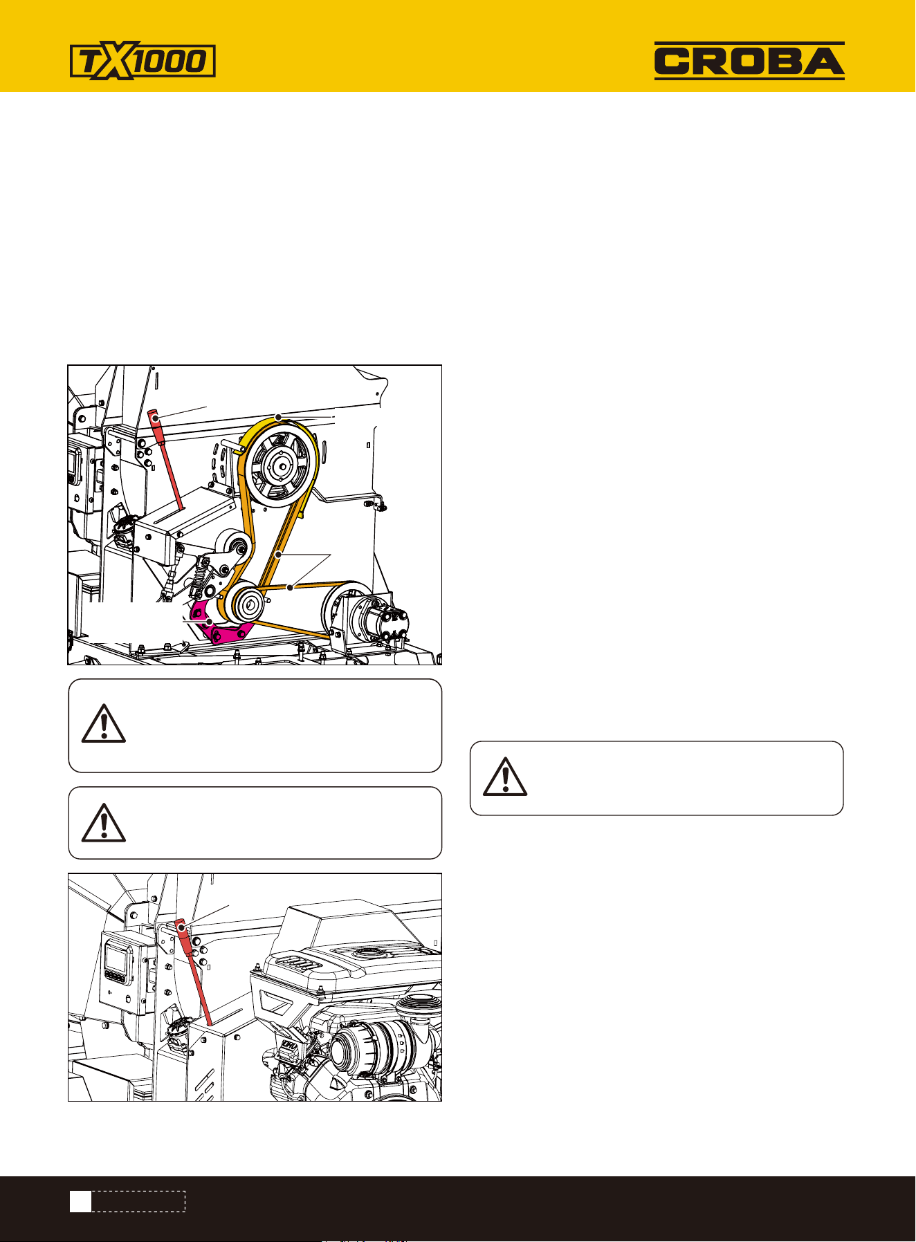
Belt
Always replace both belts, as they come in
a matched set. This is required for proper
operation.
Wait for the machine to cool down
completely.
NOTE: Check and re-tighten belts after
initial break-in period, one hour of use.
1.Remove the belt guard.
2.Push the clutch belt lever to the right to loosen the belt.
3.Remove the pulley guard.
4.Loosen the belt pressure plate.
5.Remove the old belt and replace it with a new one.
6.Push the clutch belt lever to the left to tighten the belt,
then adjust the belt pressure plate so that it is 5–8 mm
from the belt.
7.Reinstall the pulley guard and belt guard following the
steps above.
8. Reset the belt clutch handle. Start the engine and run it
at full speed. Then, engage the belt clutch handle to the
3/4 position. After 3–5 seconds, fully engage the handle.
Under normal conditions, replace hydraulic oil every 2000
hours or annually (1000 hours or every 6 months under
severe conditions), always using anti-wear hydraulic oil
and maintaining the oil level at three-quarters of the tank
to prevent air intake, pressure loss, and slow machine
operation.
The hydraulic oil should be tested every 250 hours for
signs of aging. The signs of aging include:
• The color of the hydraulic oil changes.
• The smell of hydraulic oil has changed.
• It feels that there is dirt or sand in the hydraulic oil.
• Hydraulic components fail regularly.
• The operating noise is larger than normal.
• Slipping Hazard: Leaks can cause hydraulic fluid to accu-
mulate on the ground, creating slippery conditions that
may lead to serious injury. Clean up any spilled oil
promptly and repair leaks immediately.
• High-Pressure Injection Hazard: Hydraulic oil under high
pressure—such as in hydraulic cylinders—can be eject-
ed from leaks with great force. This may result in
serious burns or even injection injuries where oil pene-
trates the skin. If this occurs, seek immediate medical
attention.
• Burn Hazard: Hydraulic components (e.g., pumps,
motors) and the oil itself may become extremely hot
during operation. Contact with these parts can cause
severe burns.
• Personal Protective Equipment (PPE): Always wear
appropriate protective equipment—such as safety
goggles, gloves, and protective clothing—during opera-
tion and maintenance of the hydraulic system.
• Fire and Explosion Risk: Hydraulic oil is flammable and
can evaporate under high temperatures, posing serious
risks such as fire or explosion. Keep hydraulic oil away
from ignition sources, including open flames, sparks,
and smoking areas.
Pulley guard
Belt pressure
plate
Belt clutch handle
Belt clutch handle
MAINTENANCE
OIL RETURN FILTER
RECOMMENDED OIL
Fire and Explosion Risk: Hydraulic oil is flammable and can
evaporate under high temperatures, posing serious risks
such as fire or explosion. Keep hydraulic oil away from
ignition sources, including open flames, sparks, and smok-
ing areas.
Replace the hydraulic oil filter every 500 working hours or
whenever the hydraulic oil is changed, whichever comes
first.
Use a 10-micron filter and wear protective plastic gloves
to avoid skin contact with oil. Dispose of used oil and
filters responsibly and in accordance with environmental
regulations.
Replacement Steps:
1. Unscrew the top of the filter housing and remove the old
filter element.
2. Insert the new filter element and securely screw the
filter housing back in place
Use 4-stroke motor oil that meets or exceeds the require-
ments for APl service category SJ or later (or equivalent).
Always check the API service label on the oil container to be
sure it includes the letters SJ or later (or equivalent).
SAE 10W-30 or 5W-30 is recommended for general use. Use
a full synthetic 5W-30 for starting/operating temperatures
between 5°F (-15C) and-13°F (-25C). Other viscosities
shown in the chart may be used when the average tempera-
ture in your area is within the indicated range.
AMBIENT TEMPERATURE
This engine is certified to operate on unleaded gasoline with
a pump octane rating of 86 or higher (a research octane
rating of 91 or higher). Refuel in a well ventilated area with
the engine stopped. If the engine has been running, allow it
to cool first. Never refuel the engine inside a building where
gasoline fumes may reach flames or sparks. You may use
unleaded gasoline containing no more than 10% ethanol
(E10) or 5% methanol by volume. In addition, methanol must
contain cosolvents and corrosion inhibitors. Use of fuels
with content of ethanol or methanol greater than shown
above may cause starting and/or performance problems. It
may also damage metal, rubber, and plastic parts of the fuel
system. Engine damage or performance problems that
result from using a fuel with percentages of ethanol or meth-
anol greater than shown above are not covered under the
Warranty.
Recommended Fuel
REFUELING
All the hydraulic hoses should be regularly inspected for
chafing and leaks. The hydraulic system is pressurized to
150 Bar and thus the equipment containing it must be kept
in good condition.
Identify the hoses that run to the top motor. These have the
highest chance of damage as they are constantly moving. If
any hydraulic components are changed new seals should be
installed during reassembly. Fittings should then be retight-
ened.
CHECK HOSES
All engine servicing must be performed in accordance with
the Engine Manufacturer's handbook provided with the
machine. FAILURE TO ADHERE TO THIS MAY INVALIDATE
WARRANTY AND/OR SHORTEN THE LIFE OF THE ENGINE.
ENGINE SERVICING
29
www.mechmaxx.com
MAINTENANCE

Problem
TROUBLESHOOTING
RemedyCause
Engine fails to start 1. Spark plug wire is disconnected.
2. Out of fuel or stale fuel.
3. Engine and/or Fuel valve is not in
ON position.
4. Choke lever is not in CLOSE position.
5. Blocked fuel line.
6. Fouled spark plug.
7. Engine flooding.
1. Attach spark plug wire securely to
spark plug.
2. Fill with clean, fresh gasoline.
3. Engine and Fuel valve must be in ON
position.
4. Choke lever must be in CLOSE position
for a cold start.
5. Clean fuel line.
6. Clean, adjust gap, or replace.
7. Wait a few minutes to restart, but do
not prime.
Engine runs erratically 1. Connect and tighten spark plug wire.
2. Move choke lever to OPEN position.
3. Clean fuel line. Fill tank with clean,
fresh gasoline.
4. Clear vent.
5. Drain fuel tank. Refill with fresh fuel.
6. Clean or replace air cleaner.
7. Refer to engine manual.
1. Spark plug wire is loose.
2. Unit running with Choke lever in
CLOSE position.
3. Blocked fuel line or stale fuel.
4. Vent plugged.
5. Water or dirt in fuel system.
6. Dirty air cleaner.
7. Improper carburetor adjustment.
Engine overheats 1. Fill crankcase with proper oil.
2. Clean air cleaner.
3. Remove housing and clean.
4. Refer to engine manual.
1. Engine oil level low.
2. Dirty air cleaner.
3. Air flow restricted.
4. Carburetor not adjusted properly.
Chipping action seems
too slow, cutting disk
stalls, or no material
is discharged when
engine is running
1. Run the engine at full throttle.
2. Tighten or replace drive belt.
3. Sharpen or replace knives.
4. Remove any built-up debris and turn
cutting disk with a wooden stick to be
sure it turns freely.
5. Clean out debris.
1. Engine speed is too slow causing
belt to slip.
2. Drive Belt is loose or damaged.
3. Knives are dull or damaged.
4. Cutting disk is jammed by
debris from the feed hopper and
discharge chute.
5. Discharge chute is clogged.
30
www.mechmaxx.com
TROUBLESHOOTING

Problem RemedyCause
The belt frays or rolls
over the pulley
When chipping,
branch seems to
vibrate and move
about excessively with
unusual noise
Chipper Knives are
hitting the wear plate
The machine's wheels
track left or right
while being towed
Low tire pressure.
The gap between the knives and wear
plate is set incorrectly.
Add air to tires.
Adjust the gap.
1.Sharpen or replace knives.
2. Loosen the knife mounting screws, reset
the knives, and tighten the screws.
3. Adjust the gap.
4. Allow unit to clear itself before adding
more material to the hopper.
1. Check drive belts for wear and hard
spots. File off any nicks on the pulley.
2. Replace drive belts.
3. Adjust pulleys.
1. Rotor drive pulley groove may be
nicked.
2. Drive belts may be stretched.
3. Pulleys may be misaligned.
1. Knives are dull or damaged.
2. Knives are not properly seated on
the cutting disk.
3. The gap between the knives and
wear plate is too large.
4. Rotor is overloaded with material.
31
www.mechmaxx.com
TROUBLESHOOTING
32
www.mechmaxx.com
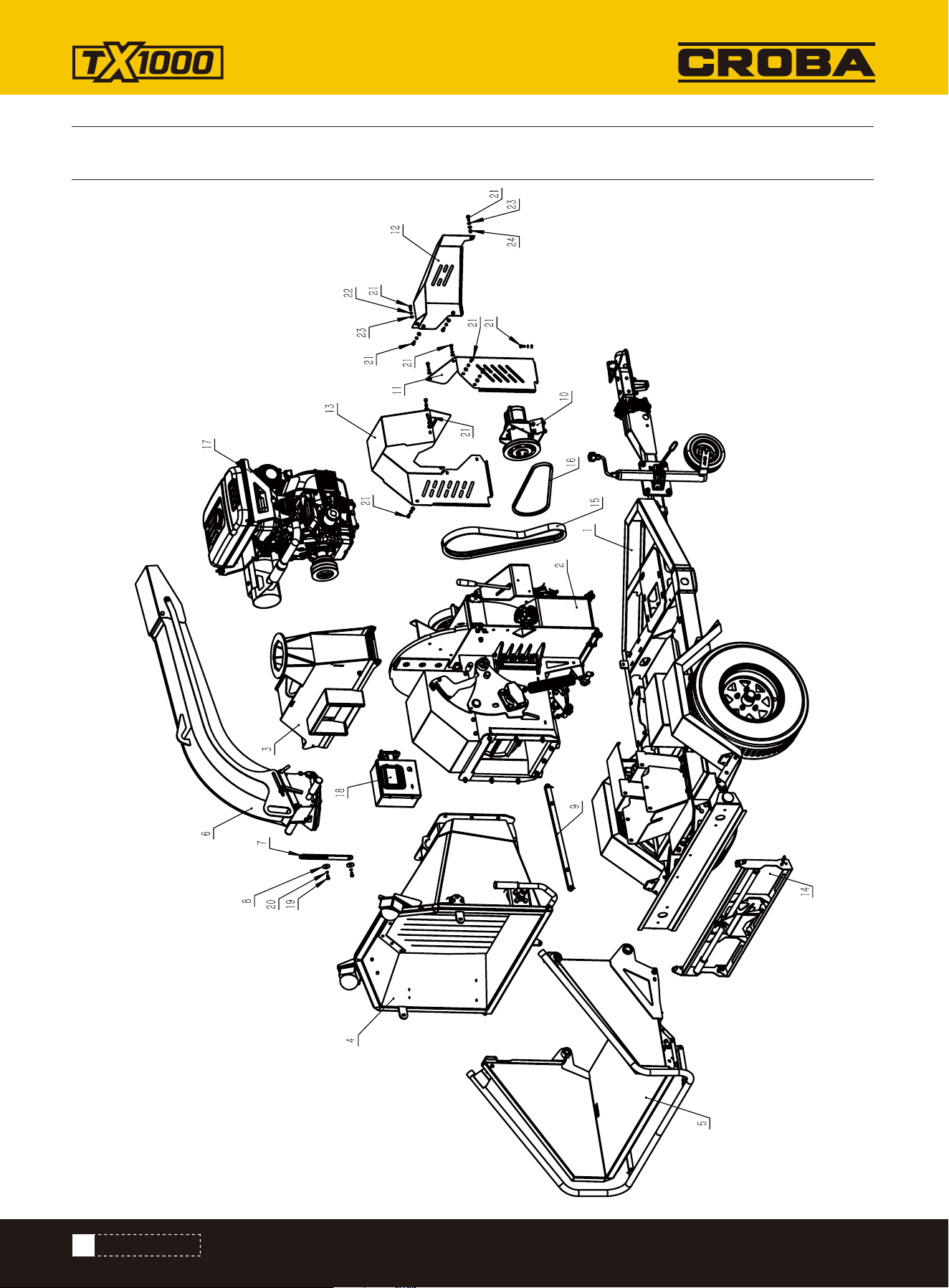
PARTS DIAGRAM
PARTS DIAGRAM

33
www.mechmaxx.com
PARTS LIST
NO. Description Qty.
1
2
3
4
5
6
7
8
9
10
11
12
Chasis assembly
Disc house assembly
Disc cover assembly
In-feed hopper
Feed tray
Discharge chute assembly
Top cover plate
Pressure plate
Direction-changing rod
Pump assembly
Right belt cover
Left belt cover
1
1
1
1
1
1
1
2
1
1
1
1
NO. Description Qty.
13
14
15
16
17
18
19
20
21
22
23
24
Top belt cover
Folding baffle plate assembly
Disc Belt 2SB1505LE
Pump belt AV13x1185le(A46)
Engine assembly
Controller assembly
Hex bolt M8*16
Spring washer 8
Hex bolt M8*20
Spring washer 8
Flat washer 8
Hex nut M8
1
1
1
1
1
1
2
2
12
11
13
1
PARTS DIAGRAM
34
www.mechmaxx.com
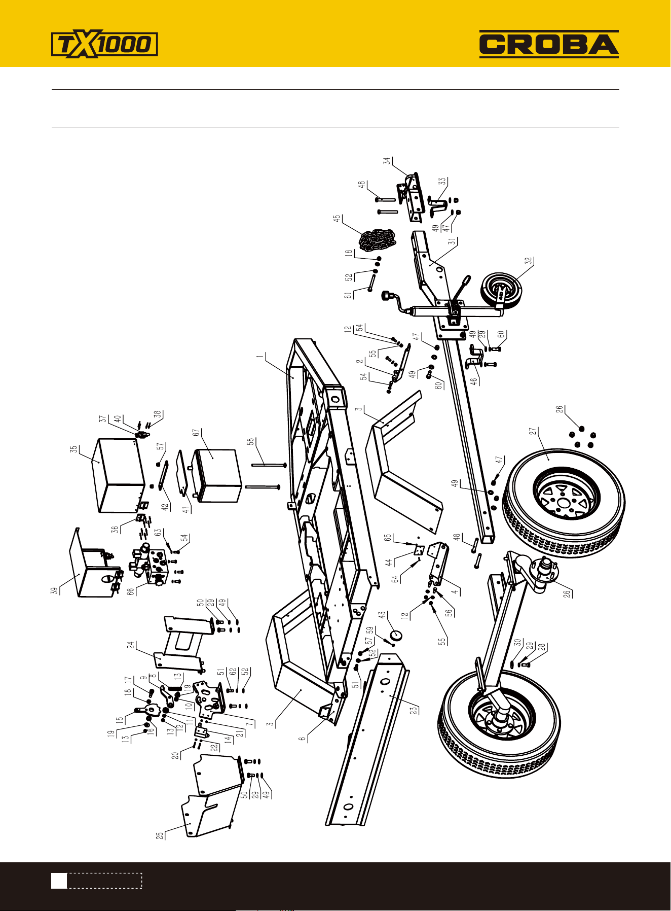
PARTS DIAGRAM
PARTS DIAGRAM

35
www.mechmaxx.com
PARTS LIST
NO. Description Qty.
1
2
3
4
5
6
7
8
9
10
11
12
13
14
15
16
17
18
19
20
21
22
23
24
25
26
27
28
29
Chassis base
Mudguard front right bracket
Mudguard
Mudguard rear right bracket
Mirror tyre mudguard front right bracket
Mirror tyre mudguard rear right bracket
Direction-changing fixing plate
Direction-changing spring
Fixing plate pin-lift
Direction-changing bearing Sleeve
Bearing 6001-2RZ
Flat washer 8
Thin nut M8
Limit switch CZ-7311
Direction-changing handle
Direction-changing bearing bushing
Screw φ12×20-M10x16.4
Thin nut M10
Washer 8
Screw M4*35
Thin nut M4
Flat washer 4
Rear light plate
In-feed hopper bracket
In-feed hopper support plate
Torsion bar
Wheel φ594x165
Hex bolt M12*30
Sping washer 12
1
1
2
1
1
1
1
1
1
1
1
17
3
2
1
1
1
2
2
4
4
4
1
1
1
1
2
4
14
NO. Description Qty.
30
31
32
33
34
35
36
37
38
39
40
41
42
43
44
45
46
47
48
49
50
51
52
53
54
55
56
57
58
Washer 12
Tow bar
Jockey wheel 8"
Coupler bent bracket
Coupler latch
Battery cover
Battery cover hinge
Small latch
Rivet 3*10
Solenoid valve cover
Small latch
Battery top rubber
Battery top plate
Yellow reflector plate
White reflector plate
Safty chain
Tow bar bent bracket
Hex nut M12
Hex bolt M12*90
Flat washer 12
Hex bolt M12*25
Hex bolt M10*25
Flat washer 10
Spring washer 8
Hex bolt M8*20
Hex nut M8
Hex bolt M8*25
Hex nut M10
Square bolt M10*170
4
1
1
1
1
1
4
2
24
1
2
1
1
2
2
1
1
8
4
22
8
8
10
4
16
12
4
8
2
PARTS DIAGRAM

36
www.mechmaxx.com
NO. Description Qty.
59
60
61
62
63
Hex nut M6
Hex bolt M12*35
Hex bolt M10*110
Spring washer 10
Spring washer 8
2
6
1
2
4
NO. Description Qty.
64
65
66
67
Screw M3*16
Hex nut M3
Solenoid valve
Battery 12V45Ah 280A
4
4
1
1
PARTS DIAGRAM
37
www.mechmaxx.com
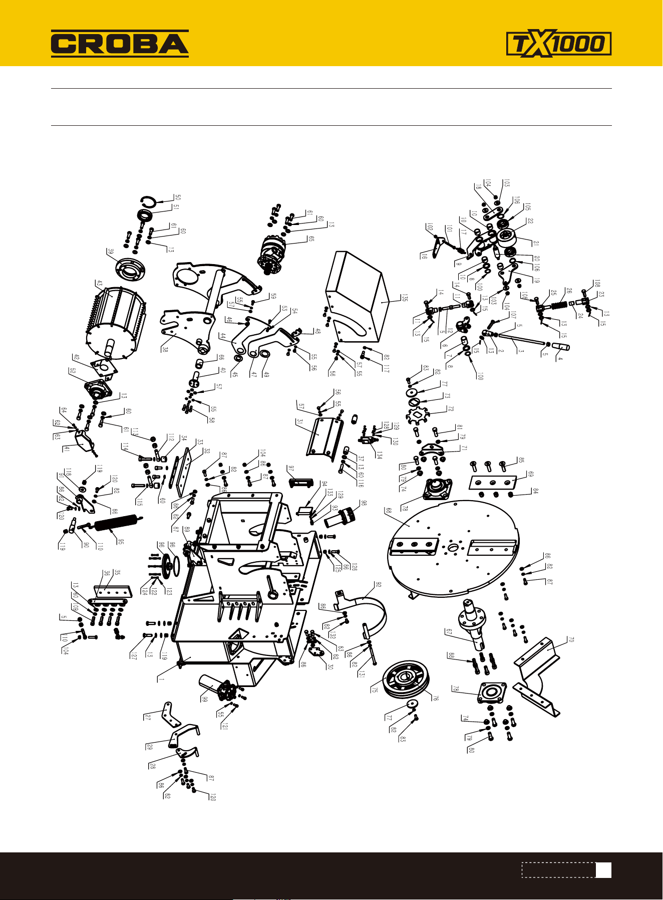
PARTS DIAGRAM
PARTS DIAGRAM

PARTS LIST
NO. Description Qty.
1
2
3
4
5
6
7
8
9
10
11
12
13
14
15
16
17
18
19
20
21
22
23
24
25
26
27
28
29
Disc Frame house
Handle rotating
Handle rotating rod
Handle bar M12*100
Hex nut M12
Clutch handle shift sleeve
Shift bearing φ25xφ29x40
Washer φ25xφ37x3
Clutch connecting rod
Clutch connecting rod sleeve
Two sides screw-Y head
Two sides screw rod
Flat washer 12
Pin 12*35
Cotter pin 3.2*22
Handle spring fixing plate
Handle spring φ22xφ2x70
Clutch connecting plate A
Clutch connecting plate B
Clutch connecting shaft
Clutch connecting tension wheel
Tension wheel shaft
Tension nut head
Tension sleeve φ15xφ18x25
Tension bolt head
Tension spring
Plate 1
Plate 3
Plate 2
1
1
1
1
7
1
1
2
1
4
2
1
41
2
5
1
1
1
1
1
1
1
1
1
1
1
1
1
1
NO. Description Qty.
30
31
32
33
34
35
36
37
38
39
40
41
42
43
44
45
46
47
48
49
50
51
52
53
54
55
56
57
58
Hinge plate
Speed sensor cover
Bottom Anvil
Bottom anvil plate
Anvil bushing
Side Anvil
Side anvil plate
Limit stop collar
Roller bracket
Motor flange
Roller bracket shaft
Bearing end cap
Bearing base plate
Roller
Roller plate 1
Thick washer
Roller plate shaft sleeve
Roller plate 2
Roller plate 3
Thin washer
Circlip 80B
Bearing 6010-2RZ
Bearing UELFU207
Screw φ8×5-M6x12
Thin nut M6
Sping washer 8
Hex bolt M8*12
Flat washer 8
Hex bolt M8*30
2
1
1
1
2
1
1
2
1
1
2
1
1
1
2
2
2
2
2
2
1
1
1
2
2
30
16
22
8
38
www.mechmaxx.com
PARTS DIAGRAM

NO. Description Qty.
59
60
61
62
63
64
65
66
67
68
69
70
71
72
73
74
75
76
77
78
79
80
81
82
83
84
85
86
87
88
89
90
Hex bolt M8*20
Spring washer 12
Hex bolt M12*35
Spring washer 6
Flat washer 6
Hex bolt M6*12
Hydraulic motor
Shaft sleeve φ25xφ35x40
Disc shaft
Disc
Blade
Fan
Speedometer plate
Tachometer plate
Speed plate
Bearing bolt bushing
Pulley SPB250-02-2517-φ50
Key B14x9x45
Pulley end plate
Bearing UCFU210
Spring washer 14
Hex bolt M14*40
Hex bolt M14*45
Spring washer 10
Hex bolt M10*25
Hex nut M14
Screw M14*60
Flat washer 10
Hex bolt M10*30
Screw M14*40
Roller spring left base
Roller spring
2
22
12
2
2
2
1
2
1
1
2
2
1
1
1
8
1
1
2
2
14
6
2
35
8
6
6
45
23
6
1
2
NO. Description Qty.
91
92
93
94
95
96
97
98
99
100
101
102
103
104
105
106
107
108
109
110
111
112
113
114
115
116
117
118
119
120
121
122
Roller sping right base
Pulley cover
Shrapnel pin
Pin φ12×60
Roller spring φ50xφ6x332
Oil outlet flange
Level gauge
Breathing cap
Return filter
Circlip B tye 25
Eye Bolt M8*70
Thin nut M8
Washer 10
Thin nut M10
Bearing 6206-2Z
Circlip B tye 30
Pin B type 12*55
Pin B type 12*40
Screw M12*40
Eye bolt M12*70
Hex bolt M10*40
Eye bolt M14*70
Hex nut M14
Screw M12*60
Screw M12*25
Hex bolt M12*50
Screw φ12×20-M10x16.4
Washer 12
Hex nut M12
Hex bolt M10*20
Screw M8*20
Spring washer 5
1
1
1
1
2
1
1
1
1
2
1
1
4
12
2
2
1
2
4
4
2
2
4
2
2
2
2
2
12
6
4
8
39
www.mechmaxx.com
PARTS DIAGRAM

NO. Description Qty.
123
124
125
126
127
128
129
Flat washer φ5.5xφ10x1
Screw M5*20
Hex nut M10
Hex bolt M10*35
Hex bolt M12*40
Screw M4*20
Spring washer 4
8
8
2
2
8
4
5
NO. Description Qty.
130
131
132
133
134
135
Flat washer 4
Hex bolt M10*120
Hex bolt M10*20
Screw M4*8
Limit switch ME8112
Roller cover
4
1
1
1
1
1
40
www.mechmaxx.com
PARTS DIAGRAM
NO. Description Qty.
1
2
3
4
Disc top cover
Sensor top cover
Pin B type 12*215
Flat washer 12
1
1
1
2
NO. Description Qty.
5
6
7
8
Cotter pin 3.2*22
Spring washer 6
Flat washer 6
Hex bolt M6*16
1
3
3
3
41
www.mechmaxx.com
PARTS DIAGRAM
PARTS LIST
PARTS DIAGRAM
42
www.mechmaxx.com
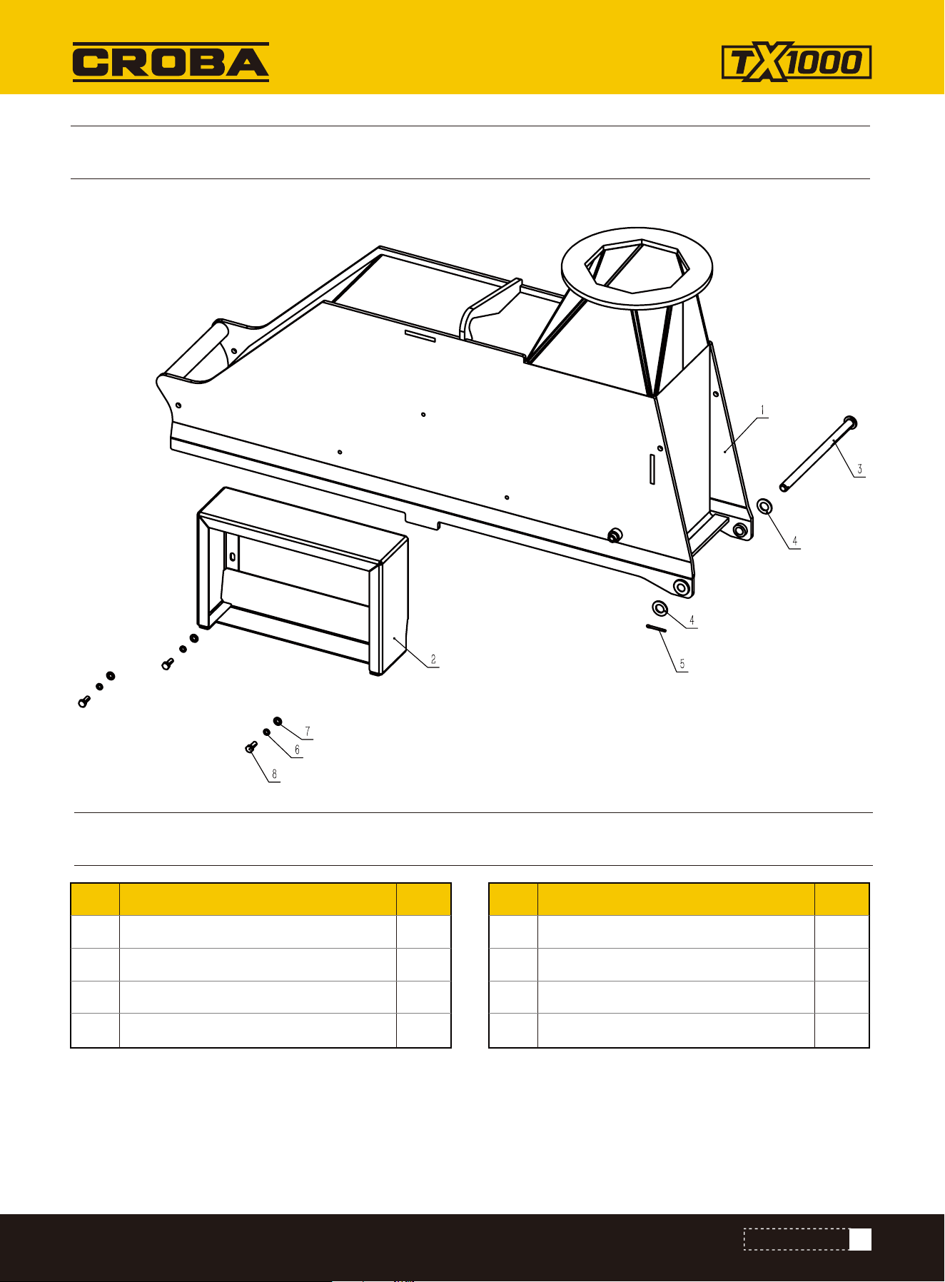
PARTS DIAGRAM
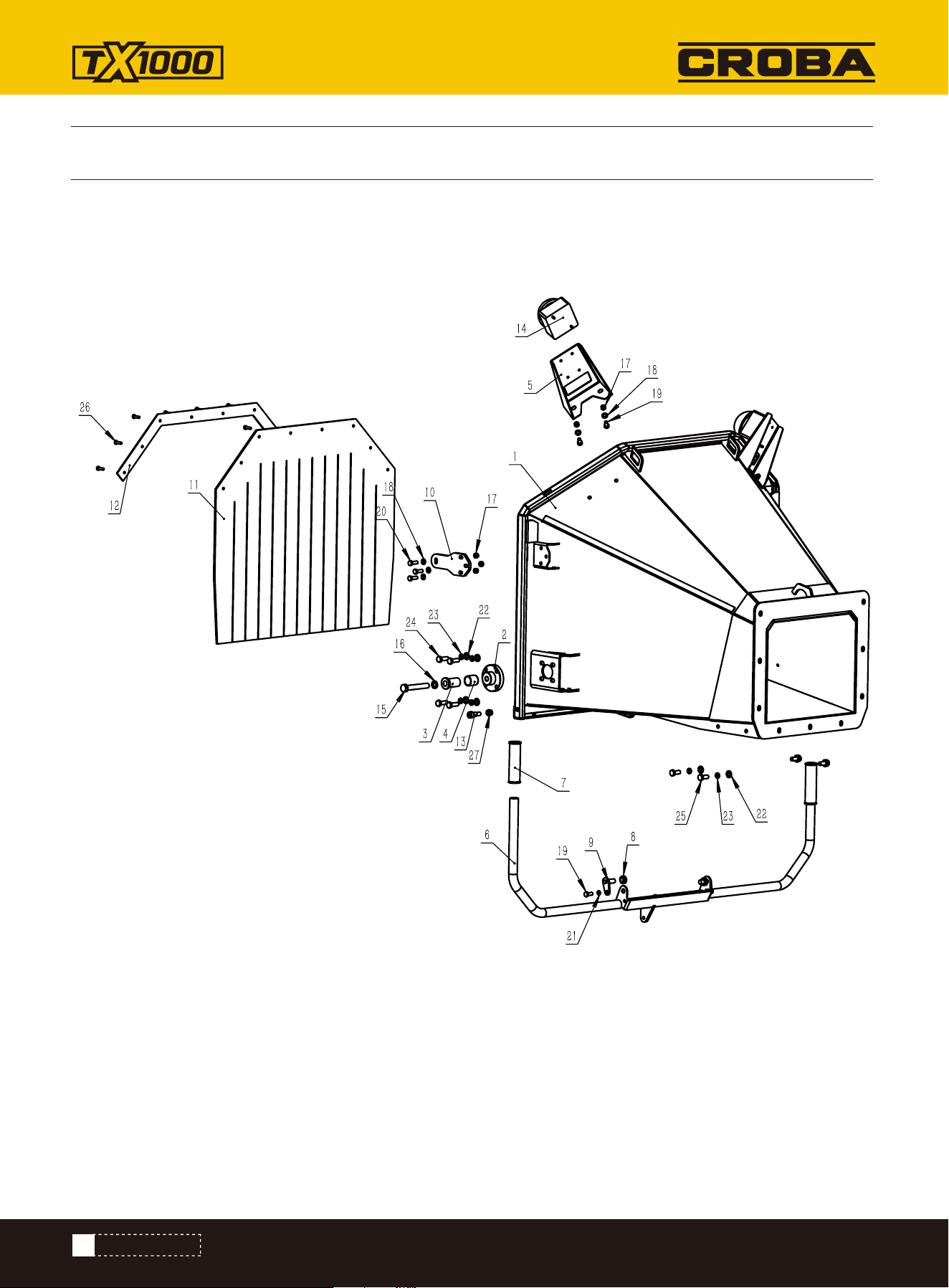
PARTS DIAGRAM

NO. Description Qty.
1
2
3
4
5
6
7
8
9
10
11
12
13
14
In-feed hopper
Feed tray mounting base
Shaft sleeve
Graphite bearing φ29xφ25x30
Emergency stop button box
Direction-changing rod
Pipe sleeve
Bearing GE12Cφ22xφ12x10
Trunnion
Latch seat
Rubber baffle
Baffle plate
Screw φ12×16-M10x16.4
Emergency stop button
1
2
2
2
2
1
2
2
2
2
1
1
2
2
NO. Description Qty.
15
16
17
18
19
20
21
22
23
24
25
26
27
Hex bolt M14*90
Spring washer 14
Thin nut M8
Flat washer 8
Hex bolt M8*20
Hex bolt M8*25
Spring washer 8
Flat washer 10
Spring washer 10
Hex bolt M10*30
Hex bolt M10*25
Hex bolt M6*20
Hex nut M10
2
2
10
10
6
6
2
12
12
8
4
8
2
43
www.mechmaxx.com
PARTS DIAGRAM
PARTS LIST
44
www.mechmaxx.com
PARTS DIAGRAM
PARTS DIAGRAM

45
www.mechmaxx.com
PARTS DIAGRAM
NO. Description Qty.
1
2
3
4
5
6
7
8
9
10
11
12
13
14
15
16
17
Feed tray
Cover plate
Emergency stop shaft
Return rod base
Return rod
Graphite bearing φ18xφ12x19
Return compression spring
Return spring
Spring latch
Emergency stop bar
Emergency stop connection rod
Pipe end cover
Bearing GE12Cφ22xφ12x10
Trunnion
Plate
Eye bolt M5*35-φ4.2
Spring washer 8
1
1
1
1
1
1
1
2
2
1
2
2
4
2
1
2
1
NO. Description Qty.
18
19
20
21
22
23
24
25
26
27
28
29
30
31
32
33
Thin nut M8
Screw φ12×16-M10x16.4
Thin nut M5
Thin nut M10
Spring washer 6
Flat washer 6
Hex bolt M6*16
Pin B type 8*20
Flat washer 8
Cotter pin 2*16
Spring washer 8
Hex bolt M8*16
Screw M4*35
Thin nut M4
Screw M4*8
Limit switch CZ-7311
1
4
2
2
10
10
10
4
4
4
2
2
2
2
8
1
PARTS LIST
46
www.mechmaxx.com
PARTS DIAGRAM
PARTS DIAGRAM

47
www.mechmaxx.com
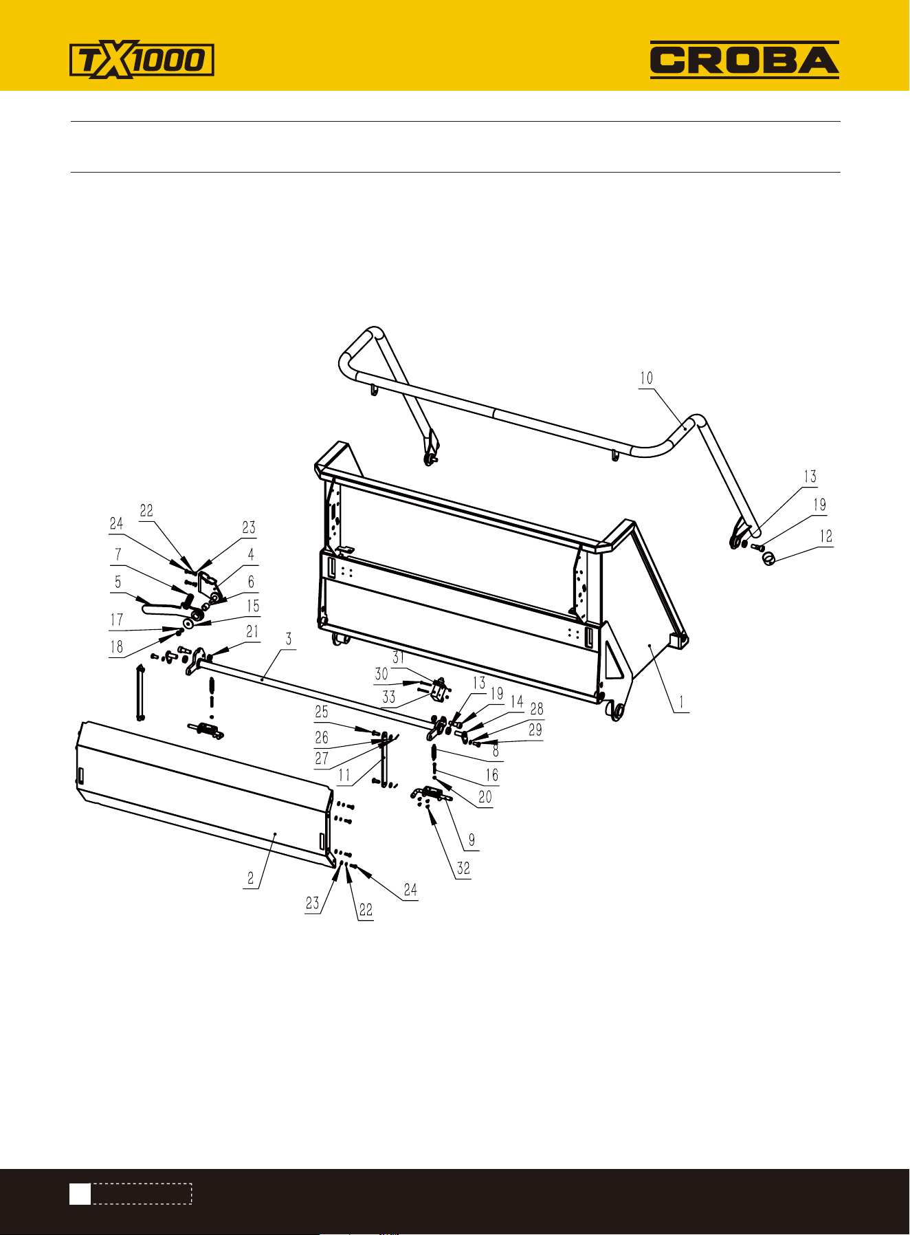
PARTS DIAGRAM
NO. Description Qty.
1
2
3
4
5
6
7
8
9
10
11
Outlet base
Outlet deflector
Thin plate
Base Plate
Dam board
Press board
Compression bolt
Function lever
Adjusting board
Discharge tank
Pin shaft
1
1
4
2
2
1
1
1
1
1
1
NO. Description Qty.
12
13
14
15
16
17
18
19
20
21
22
R type Pin 03*45
B type pin 12*195
Handle sleeve φ25
Hex nut M6
Flat washer 10
Thin nut M10
Hex bolt M10*30
Hex bolt M10*40
Flat washer 12
Adjustable locking handle
Cotter pin 3.2*22
1
1
2
2
11
11
2
8
2
1
1
PARTS LIST
48
www.mechmaxx.com
PARTS DIAGRAM
PARTS LIST
PARTS DIAGRAM
NO. Description Qty.
1
2
3
4
Direction-changing linkage sleeve
Direction-changing board
Thin nut M8
Flat washer 8
2
2
2
6
NO. Description Qty.
5
6
7
Hex bolt M8*30
Pin B tye 8*26
Cotter pin 2*20
2
2
2
49
www.mechmaxx.com
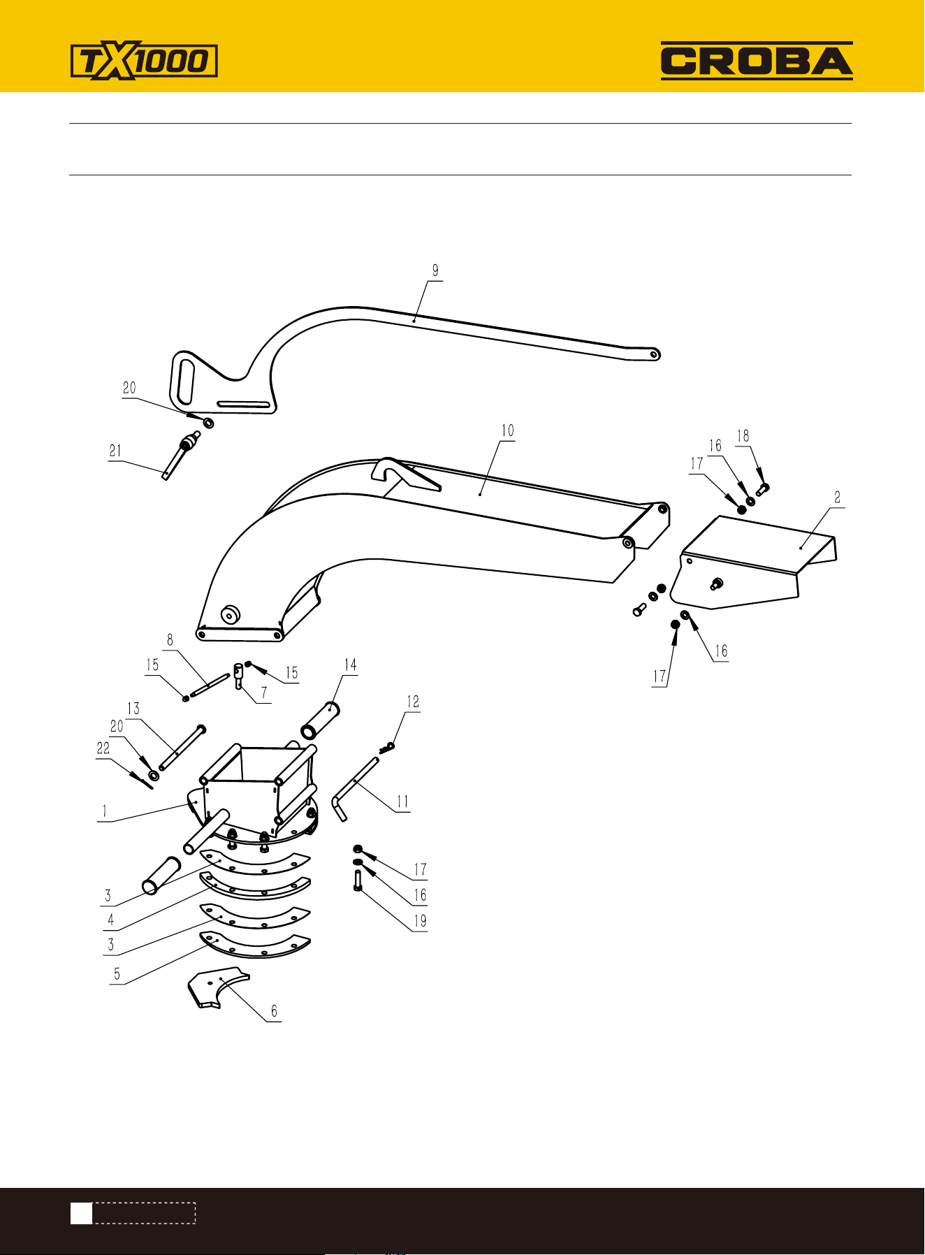
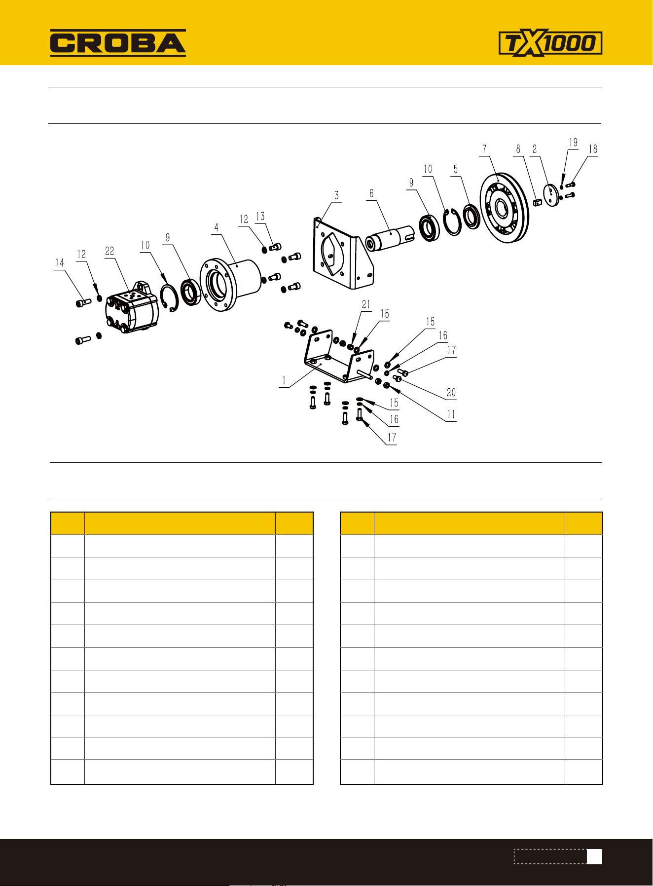
NO. Description Qty.
1
2
3
4
5
6
7
8
9
10
11
Oil pump base
Pump end board
Pump bracket board
Pump Transimission bracket
Pump transimission end cap
Pump transmission shaft
Pulley 180-1-1601-φ40
Shaft key B12x8xL20
Bearing 6008-2RZ
Circlip B type 68B
Hex nut M8
1
1
1
1
1
1
1
1
2
2
2
NO. Description Qty.
12
13
14
15
16
17
18
19
20
21
22
Spring washer 10
Hex screw M10*20
Hex screw M10*30
Flat washer 8
Spring washer 8
Hex bolt M8*25
Hex bolt M6*20
Spring washer 6
Hex bolt M8*16
Hex nut M8
Pump CBWKA-F308-AFΦ11L
6
4
2
10
6
6
2
2
2
2
1
PARTS LIST
PARTS DIAGRAM
PARTS DIAGRAM
50
www.mechmaxx.com
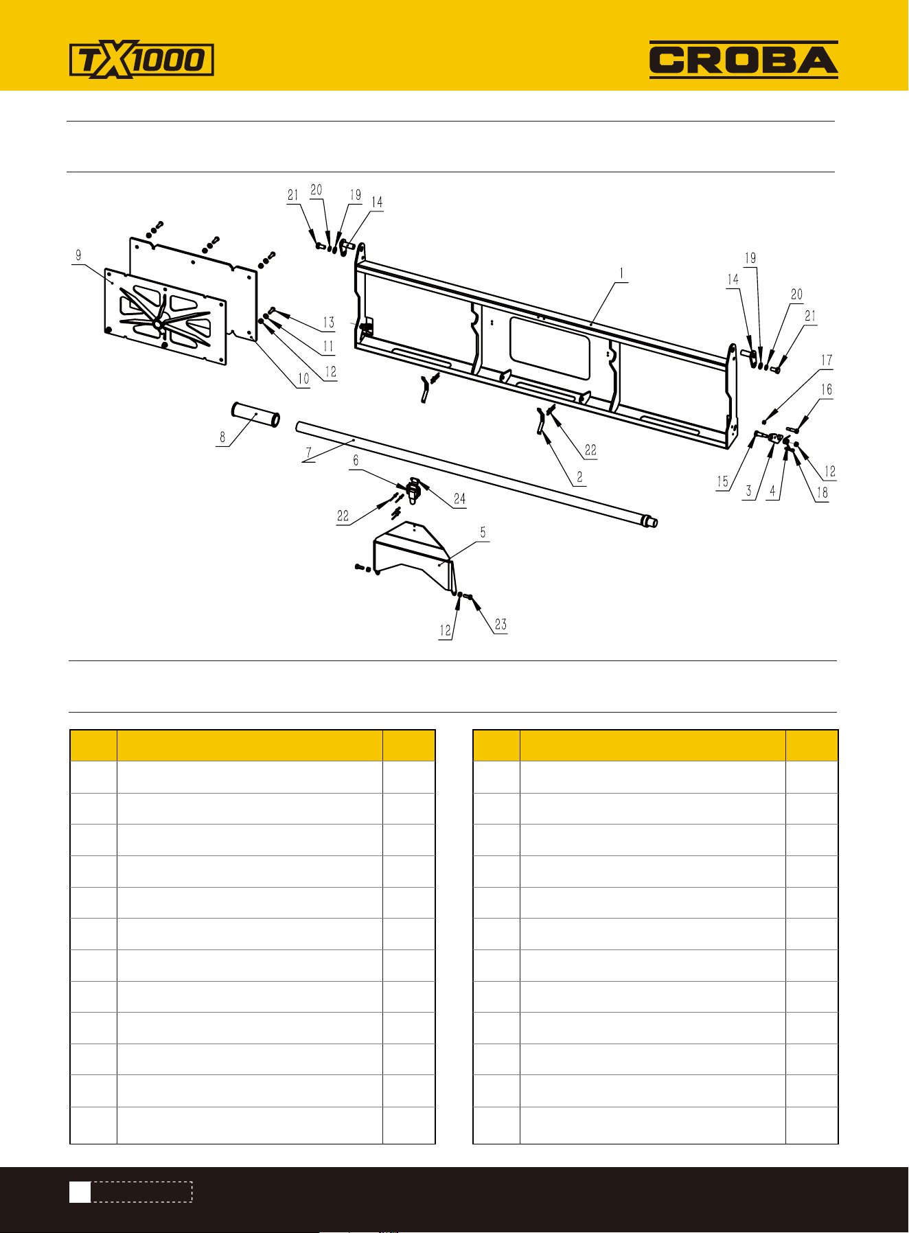
NO. Description Qty.
1
2
3
4
5
6
7
8
9
10
11
12
Folding baffle plate
Folding spring plate
Folding lock board
Torsion spring φ12xφ1.5x11
Pressure plate
Small latch
Push-out arm
Handle sleeve
Push-out plate
Push-out base plate
Flat washer 6
Thin nut M6
1
2
2
2
1
1
1
1
1
1
6
10
NO. Description Qty.
13
14
15
16
17
18
19
20
21
22
23
24
Hex screw M6*20
Trunnion
Hex socket Screw φ8×16-M6x12
Hex socket Screw φ6×16-M5x10
Thin nut M5
Screw M4*20
Flat washer 8
Spring washer 8
Hex bolt M8*16
Rivet 3*10
Hex bolt M6*16
Small latch
6
2
2
2
2
2
2
2
2
8
2
1
PARTS LIST
PARTS DIAGRAM
PARTS DIAGRAM
51
www.mechmaxx.com
PARTS DIAGRAM
PARTS DIAGRAM

52
www.mechmaxx.com
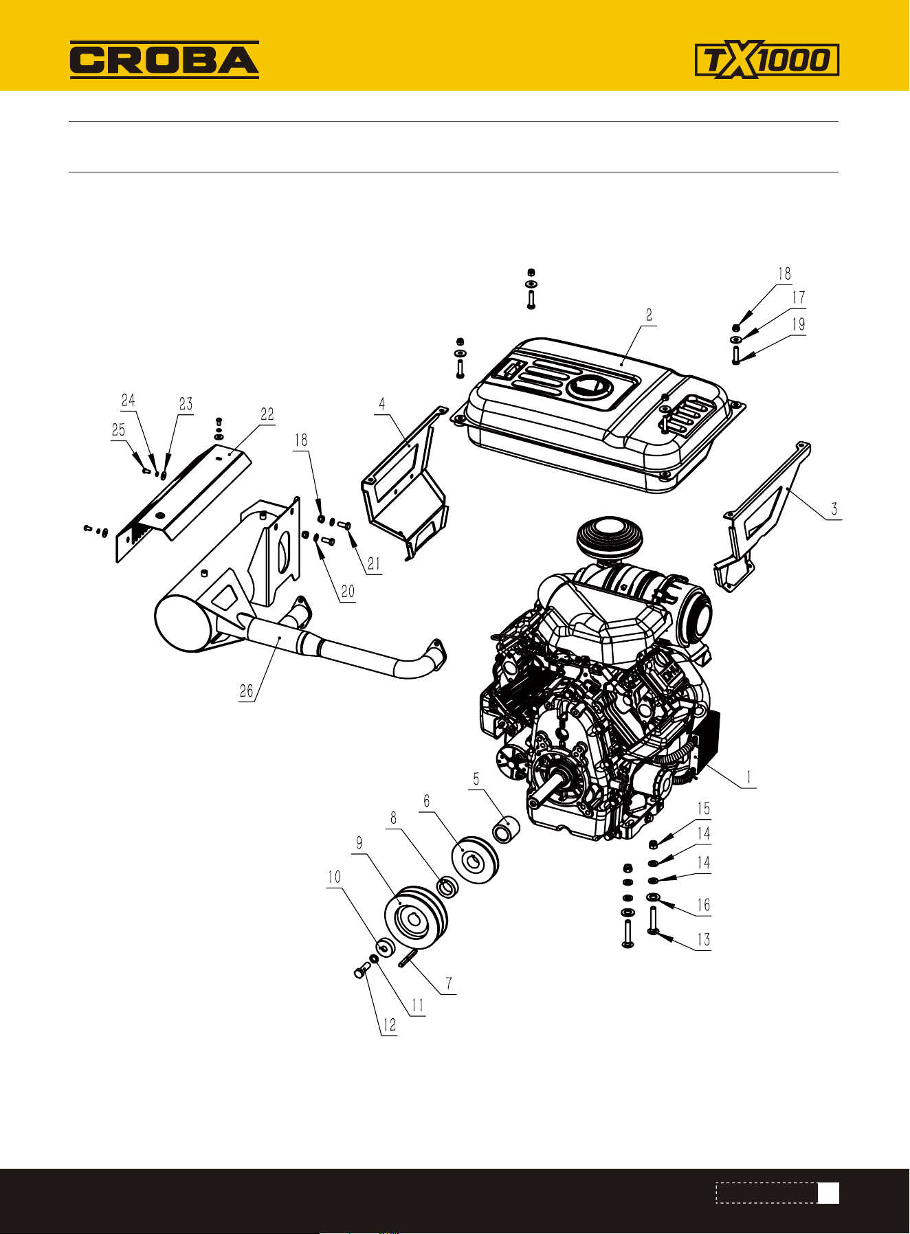
NO. Description Qty.
1
2
3
4
5
6
7
8
9
10
11
12
13
Zonsen 35HP Engine
Fuel tank
Tank right bracket
Tank left bracket
Impeller Spacer sleeve
Impeller
Engine shaft key 6.35x6.35x25
Pulley spacer sleeve
Pulley SPB125-02-2012-φ28.575
Engine shaft end cap
Spring washer 12
Hex bolt M20*1.5
Squre bolt M10*60
1
1
1
1
1
1
1
1
1
1
1
1
4
NO. Description Qty.
14
15
16
17
18
19
20
21
22
23
24
25
26
Flat washer 10
Hex nut M10
Flat washer 14
Washer 8
Hex nut M8
Hex bolt M8*35
Flat washer 8
Hex bolt M8*20
Anti-scalding cover
Flat washer 6
Spring washer 6
Screw M6*12
Muffler
8
4
4
4
6
4
4
2
1
4
4
4
1
PARTS LIST
PARTS DIAGRAM
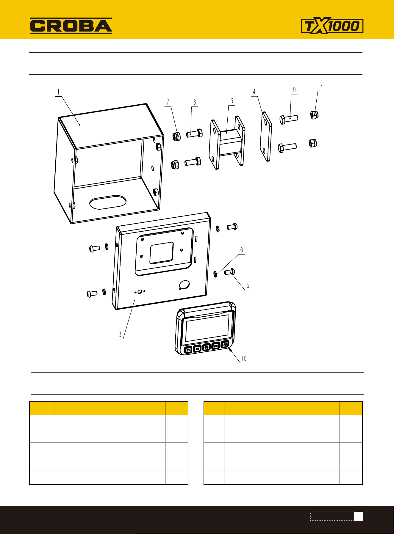
NO. Description Qty.
1
2
3
4
5
Controller box
Controller panel
Connection pipe
Controller box rubber plate
Screw M8*16
1
1
1
1
4
NO. Description Qty.
6
7
8
9
10
Spring washer 8
Hex nut M10
Hex bolt M10*25
Hex bolt M10*30
Controller
4
4
2
2
1
PARTS LIST
53
www.mechmaxx.com
PARTS DIAGRAM
PARTS DIAGRAM