Operator’s Manual
www.mechmaxx.com
WARRANTY


MAX performance, MAX Value, MAX Support
that’s Wood Chipper
Enhanced design features come standard
Engineered for the best user experience
Quality metal parts are used instead of plastic
A robust warranty supports all products
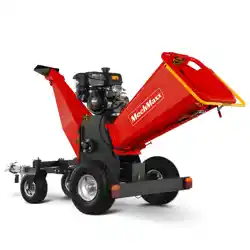
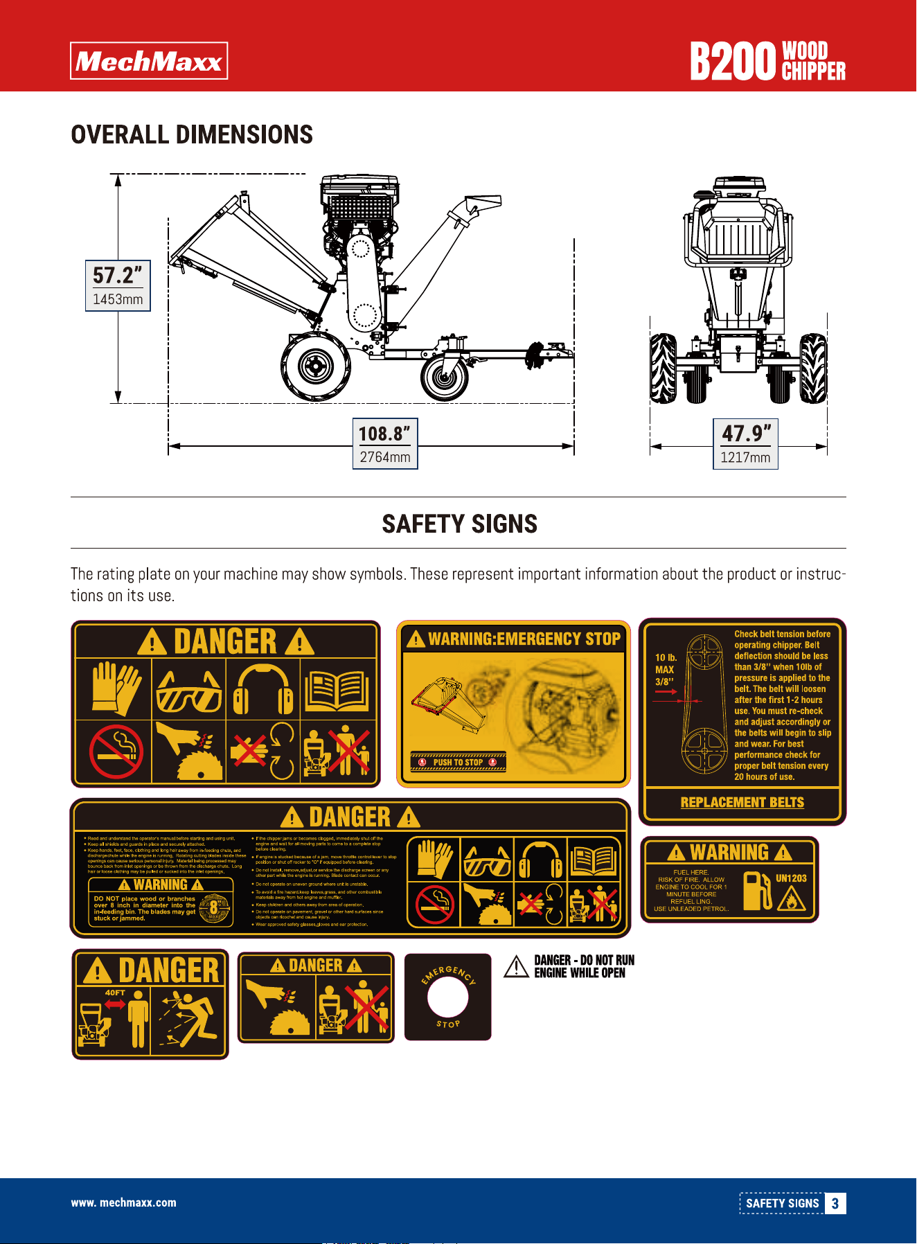
OVERALL DIMENSIONS
Budget-friendly prices make it practical
TABLE OF CONTENTS
TABLE OF CONTENTS
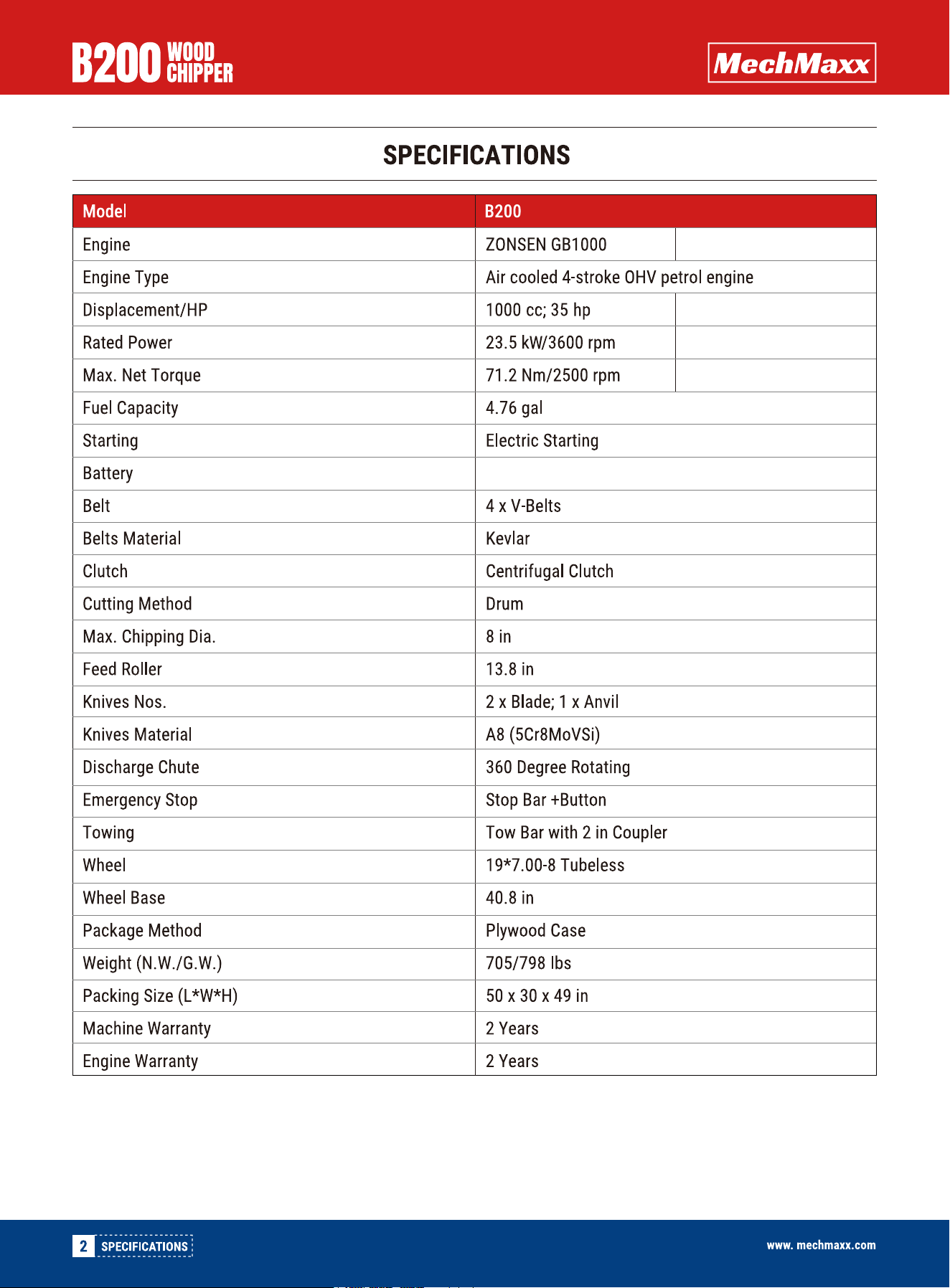
SPECIFICATIONS
SAFETY SIGNS
SAFETY
1
2
2
ADD OIL TO ENGINE
ADD GASOLINE TO ENGINE
15
15
STARTING ENGINE
15
OPERATING
16
IDLE SPEED
17
STOP ENGINE
17
PREVENTIVE MAINTENANCE
18
REGULAR MAINTENANCE CHECKLIST
18
GREASE THE INSIDE BEARING
19
GREASE THE OUTSIDE BEARING
19
KNIFE AND WEAR PLATE INSPECTION
19
KNIFE REMOVAL AND REPLACEMENT
20
BELT ADJUSTMENT
20
BELT REPLACEMENT
21
CENTRIFUGAL CLUTCH TECH TIPS
21
GENERAL SAFETY RULES
PERSONAL SAFETY
INSPECT YOUR MACHINE
4
4
4
ENGINE SAFETY
5
FUEL SAFETY
5
SPECIFIC SAFETY RULES
5
PRIOR TO STARTING
5
OPERATION SAFETY
6
FEEDING MATERIALS
6
UNCLOGGING
6
MOVING
6
MACHINE USE AND CARE
6
MAINTAINING YOUR MACHINE 7
AXLE
WHEELS
TOWER BAR MOUNT
3
4
8
9
10
11
11
11
11
TOW BAR AND GUIDING WHEEL
LOWER EXPULSION CHUTE
360 DEGREE UPPER EXPULSION CHUTE
11
12
12
BATTERY
12
IN-FEEDING CHUTE
12
TANK
12
UNPACKING THE CONTAINER
CONTENTS SUPPLIED
TO-SCALE HARDWARE
ASSEMBLY
14
KNOW YOUR MACHINE
15
OPERATION
17
TRANSPORTING
18
MAINTENANCE
22
STORAGE
23
TROUBLESHOOTING
25
26
Your new Wood Chipper offers quality construction, and
is easy and safe to operate. With proper use and care, it
is designed to give you many years of dependable
service.
Prepare to experience the durability to take on any job
with the ease, portability, and convenience of your new
Wood Chipper !
1
TABLE OF CONTENTSwww.mechmaxx.com
PARTS DIAGRAM
PARTS LIST
12 Volt, 45Ah Lead-Acid Battery
HONDA GX690
688 cc; 22 HP
13.0 kW / 3600 RPM
48.3 N·m/2500 RPM

4
SAFETY
www.mechmaxx.com
GENERAL SAFETY RULES
SAFETY
Read this manual and labels affixed to the machine to
understand its limitations and potential hazards.
Be thoroughly familiar with the controls and their proper
operation. Know how to stop the machine and disengage
the controls quickly.
Make sure to read and understand all the instructions and
safety precautions as outlined in the Engine Manufactur-
er's manual packed separately with your unit. Do not
attempt to operate the machine until you fully understand
how to properly operate and maintain the engine and how
to avoid accidental injuries and/or property damage.
If the unit is loaned, rented, sold, or used by someone
other than the original purchaser, provide this manual and
safety training before operation. The user can prevent and
is responsible for accidents or injuries that may occur to
themselves, other people, and property
Always use the correct machine for your job. Forcing the
machine may cause damage. The correct machine will do
the job more efficiently and safely at the rate it was
designed.
Always keep hands and feet away from all moving parts
during operation. Moving parts can cut or crush body
parts.
Do not touch parts that might be hot from operation.
Allow parts to cool before attempting to maintain, adjust,
or service.
Do not overreach. Do not operate the machine while
barefoot or when wearing sandals or similar lightweight
footwear. Wear protective footwear that will protect your
feet and improve your footing on slippery surfaces. Keep
proper footing and balance at all times. This enables
better control of the machine in unexpected situations.
Check your machine before starting it. Keep guards in
place and in working order. Make sure all nuts, bolts, etc.,
are securely tightened.
Never operate the machine when it is in need of repair or
is in poor mechanical condition. Replace damaged, miss-
ing, or failed parts before using it. Check for fuel leaks.
Keep the machine in safe working condition.
Do not use the machine if the engine's switch does not
turn it on or off. Any gasoline powered machine that can't
be controlled with the engine switch is dangerous and
must be replaced.
Regularly check to see that keys and adjusting wrenches
are removed from the machine area before starting it. A
wrench or a key that is left attached to a rotating part of
the machine may result in personal injury.
Avoid accidental starting. Be sure the engine's switch is
off before transporting the machine or performing any
maintenance or service on the unit. Transporting or
performing maintenance or service on a machine with its
switch on invites accidents.
If the machine should start to vibrate abnormally, stop
the engine (motor) and check immediately for the cause.
Vibration is generally a warning sign of trouble.
Stay alert, watch what you are doing, and use common
sense when operating the machine.
Always keep hands and feet away from all pinch points.
Do not permit children to operate this machine at any
time.
Keep children, pets, and other people not using the unit
away from the work area. Be alert and shut off unit if
anyone enters work area. Keep children under the watch-
ful care of a responsible adult.
Do not operate under the influence of drugs, alcohol, or
medications that impair judgment.
Dress properly. Wear heavy long pants, boots, and gloves.
Do not wear loose clothing, short pants, or jewelry of any
kind. Secure long hair so it is above shoulder level. Keep
your hair, clothing, and gloves away from moving parts.
Loose clothes, jewelry, or long hair can be caught in
moving parts.
Protect eyes, face, and head from objects that may be
thrown from the unit. Always wear safety goggles or
safety glasses with side shields when operating.
Wear appropriate hearing protection.
PERSONAL SAFETY
INSPECT YOUR MACHINE

5
SAFETY
www.mechmaxx.com
This machine is equipped with an internal combustion
engine. Do not use on or near any unimproved, forest
covered, or brush covered land unless the exhaust system
is equipped with a spark arrester meeting applicable
local, state, or federal laws.
Never start or run the engine inside a closed area. The
exhaust fumes are dangerous, containing carbon monox-
ide, an odorless and deadly gas. Operate this unit only in a
well-ventilated outdoor area.
Do not tamper with the engine to run it at excessive
speeds. The maximum engine speed is preset by the
manufacturer and is within safety limits. See engine
manual.
Keep a Class B fire extinguisher on hand when operating
this Wood chipper in dry areas as a precautionary
measure.
Fuel is highly flammable, and its vapors can explode if
ignited. Take precautions when using to reduce the
chance of serious personal injury.
When refilling or draining the fuel tank, use an approved
fuel storage container while in a clean, well-ventilated
outdoor area. Do not smoke, or allow sparks, open flames,
or other sources of ignition near the area while adding fuel
or operating the unit. Never fill the fuel tank indoors.
Keep grounded conductive objects, such as tools, away
from exposed, live electrical parts and connections to
avoid sparking or arcing. These events could ignite fumes
or vapors.
Always stop the engine and allow it to cool before filling
the fuel tank. Never remove the cap of the fuel tank or
add fuel while the engine is running or when the engine is
hot. Do not operate the machine with known leaks in the
fuel system.
Never overfill the fuel tank. Fill the tank to no more than
½ inch below the bottom of the filler neck to provide
space for expansion as the heat of the engine can cause
fuel to expand.
Replace all fuel tank and container caps securely and
wipe up spilled fuel. Never operate the unit without the
fuel cap securely in place.
Loosen the fuel tank cap slowly to relieve any pressure in
the tank.
Avoid creating a source of ignition for spilled fuel. If fuel
is spilled, do not attempt to start the engine; instead,
move the machine away from the spillage area and avoid
creating ignition sources until vapors dissipate.
When fuel is spilled on yourself or your clothes, wash your
skin and change clothes immediately.
Store fuel in containers specifically designed and
approved for this purpose.
Store fuel in a cool, well-ventilated area, safely away from
sparks, open flames, or other sources of ignition.
Never store fuel or a machine with fuel in the tank inside
a building where fumes may reach a spark, open flame, or
any other source of ignition, such as a water heater,
furnace, or clothes dryer. Allow the engine to cool before
storing in any enclosure.
Identify hazards and take preventive steps to avoid
accidents and minimize risk. Possible hazards include,
but are not limited to, moving parts, thrown objects,
weight of the machine and components, and the operat-
ing environment.
Thoroughly inspect the area in which you are working,
keeping it clean and free of debris to prevent tripping.
Operate on a flat level ground.
Before starting your wood chipper: make sure the feed
hopper and cutting housing are empty and free of all
debris, check the oil level, make sure all nuts and bolts
are tight, and check the air pressure in the tires.
Never place any part of your body where it would be in
danger if movement should occur during assembly, instal-
lation, operation, maintenance, repair, or moving.
Never place your hands, feet, or any part of your body in
the chipper hopper, discharge opening, or near or under
any moving part while the machine is running. Keep the
area of discharge clear of people, animals, buildings,
glass, or anything else that will obstruct clear discharge,
causing injury or damage. Wind can also change
discharge direction, so be aware. If it becomes necessary
to push materials to the chipper hopper, use a small-di-
ameter stick, not your hands.
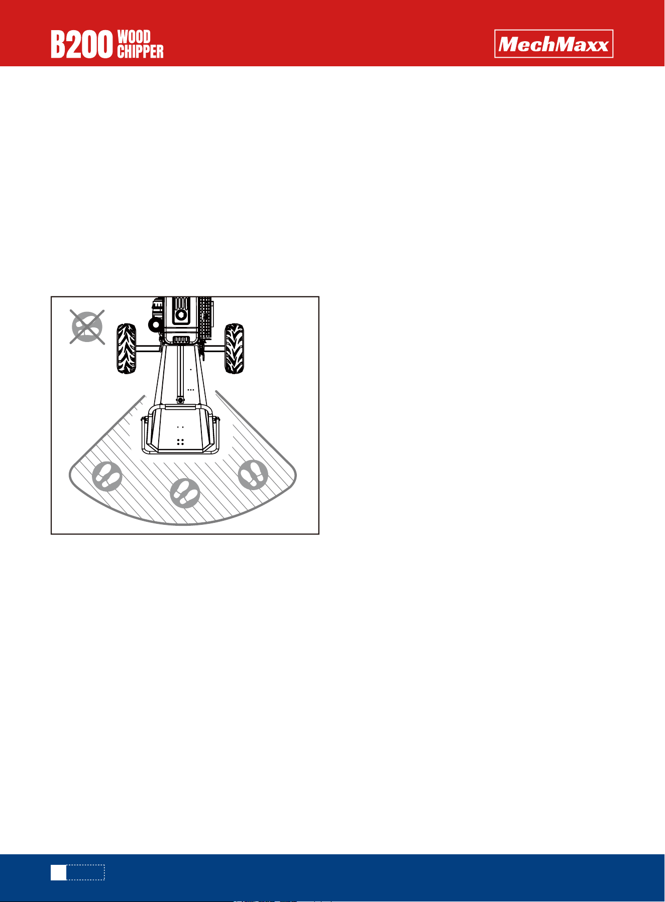
Keep bystanders and pets at least 75 feet away from the
discharge chute and feed hopper.
ENGINE SAFETY
FUEL SAFETY
SPECIFIC SAFETY RULES
PRIOR TO STARTING
OPERATION SAFETY
6
SAFETY
OPERATING ZONE
www.mechmaxx.com
Keep your face and body back from the chipper hopper and
discharge chute to avoid injury from accidental bounce
back of material.
Feed only clean materials into the machine. Foreign
matter such as soil, sand, grit, stones, pieces of metal,
etc. will damage the sharp edge of the cutting knives.
Root balls and dead wood will also dull the blades quickly
Avoid feeding pine needles, flax and cabbage tree leaves
into the machine; these stringy materials can wrap
around the rotor shaft and work their way into the bearing.
Avoid feeding short, stubby pieces of wood into the
machine; they tend to bounce and spin in the feed hopper.
Feed these short pieces together with longer pieces.
After becoming familiar with the machine, prune to suit
its capabilities.
This machine is self-feeding, do not force branches into
the blades. Allow the machine to automatically feed
through. Allow time for the machine to reach the highest
spinning revolutions before feeding the next load of
branches.
Never allow processed material to build up in the
discharge area. This can prevent proper discharge and
result in kickback from the chipper hopper.
Never attempt to unclog either the feed hopper or
discharge chute while the engine is running. Immediately
shut off the engine, allow the cutting disk to come to a
complete stop, and then remove the clogged material.
Inspect for damage and check for any loose parts that
need repair or replacement.
Whenever you leave the operating position or if you have
to remove processed material, leaves, or debris from the
machine, always shut down the engine, and ensure the
engine is switched to“off” to prevent accidental starting,
and wait for all moving parts to come to a complete stop.
Before opening the cutting disk housing, always make
sure the engine is switched off, the cutting disk is at a
complete standstill, and the belt drive is disengaged.
Move the machine at least 10 feet away from the refuel-
ing point before starting engine.
This wood chipper is for movement by hand only. Never
attempt to tow the machine on public highways, roads, or
thoroughfares.
Position the machine in such a way that it can not move
during maintenance,cleaning, adjustment, assembly of
accessories or spare parts, as well as under storage.
Always use the correct machine for your job. Forcing the
machine may cause damage. The correct machine will do
the job better and safer at the rate for which it is
designed.
Do not adjust the engine governor settings or operate the
engine above the recommended speed. The governor
controls the maximum safe operating speed of the
engine.
Always stop the engine before moving the machine, and
watch out for sharp objects that could pierce the tires.
Never reach with your hands inside the feed hopper past
the rubber flap while operating the machine.
Keep combustible substances away from the engine
when it is hot.
Do not tilt the machine while the engine is running
Never operate this machine without the feed hopper or
discharge chute properly attached.
FEEDING MATERIALS
UNCLOGGING
MOVING
MACHINE USE AND CARE

7
SAFETY
www.mechmaxx.com
This machine has two rotating cutting knives capable of
amputating hands and feet and throwing objects. Keep
hands and feet out of openings while machine is running.
Failure to observe these safety instructions could result
in serious injury or death.
Avoid contact with hot fuel, oil, exhaust fumes and hot
surfaces. Do not touch the engine or muffler. These parts
get extremely hot from operation. They remain hot for a
short time after you turn off the unit. Allow the engine to
cool before doing maintenance or making adjustments.
If the machine should start to make an unusual noise or
vibration, immediately shut off the engine, disconnect the
spark plug wire, and check for the cause. Unusual noise or
vibration is generally a warning of trouble.
Keep the engine and muffler free of grass, leaves, exces-
sive grease or carbon build up to reduce the chance of a
fire hazard.
Never douse or squirt the unit with water or any other
liquid. Keep handles dry, clean and free from debris. Clean
after each use.
When storing machine out of the reach of children and do
not allow persons unfamiliar with the machine or these
instructions to operate it. This machine can be dangerous
when used by an untrained user.
Some parts of this machine are made of plastic or rubber
and should be kept away from chemicals.
Do not alter or adjust any part of the wood chipper or its
engine that is sealed by the manufacturer or distributor.
Only a qualified service technician may adjust parts that
increase or decrease governed engine speed.
To maintain your machine, check for any misalignment or
binding of any moving parts. Parts that are broken or worn
down that may affect the machine's operation. If damage
or worn parts are identify, they should be repaired before
use. Many accidents are caused by poorly maintained
equipment.
Never cover the machine while the muffler is still hot.
Observe proper disposal laws and regulations for gas, oil,
etc., to protect the environment.
Use only attachments and accessories approved by the
manufacturer. Failure to do so can result in personal
injury.
MAINTAINING YOUR MACHINE
8
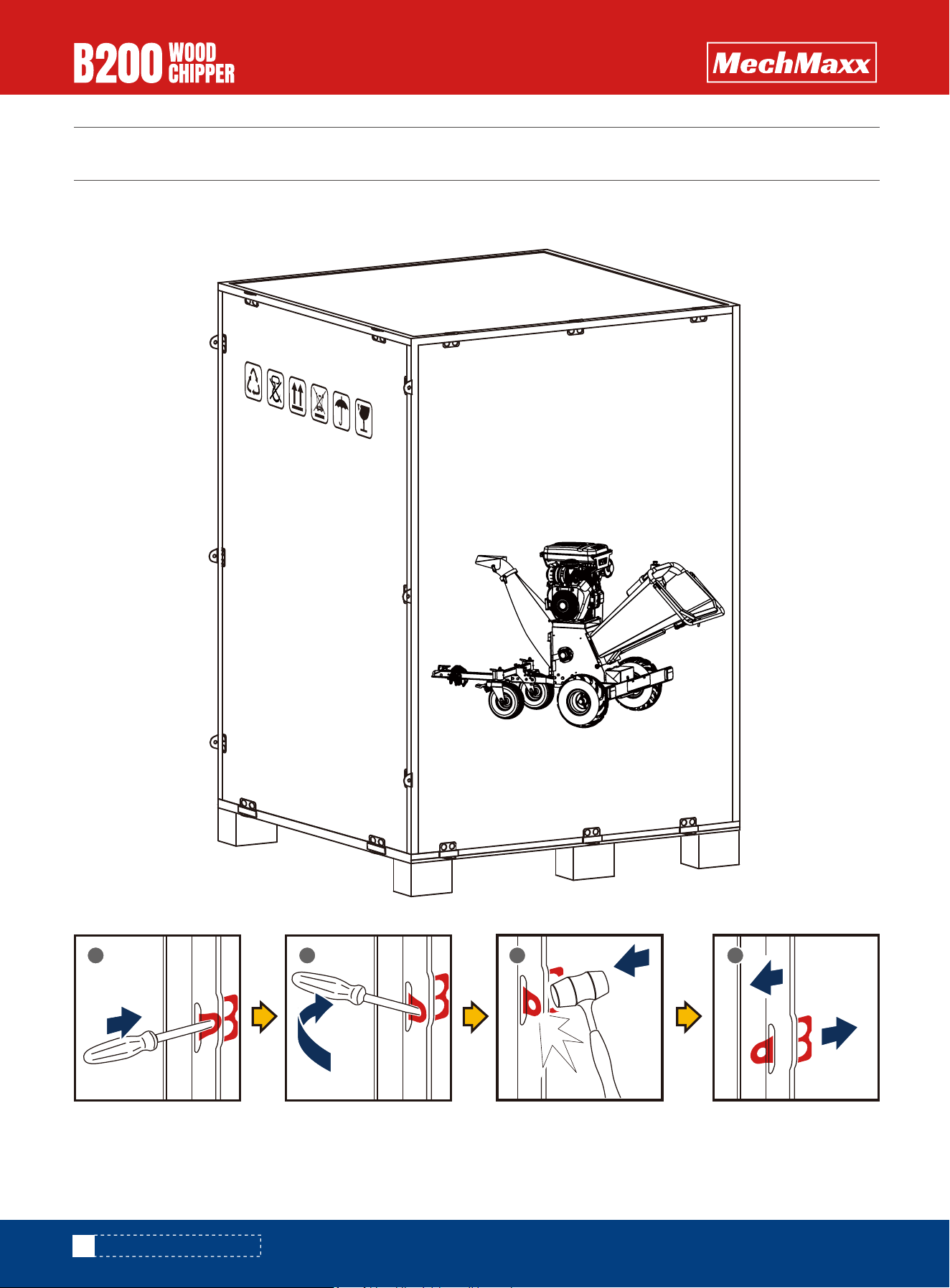
UNPACKING THE CONTAINER
UNPACKING THE CONTAINER
1 2 3 4
Use the screwdriver and hammer to open all the side locks.
GASOLINE ENGINE
POWERED WOOD CHIPPER
Mode
l Number
:
P
ackage siz
e:
www.mechmaxx.com
Gr
o
ss we
ight:
GASOLINE POWERED
WHEELBARROW
www.mechmaxx.com
9
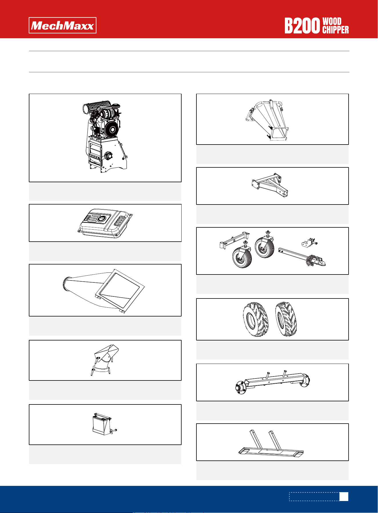
CONTENTS SUPPLIED
CONTENTS SUPPLIED
Your Wood chipper comes partially assembled and contains the following:
Engine and base frame1x
1x
1x
1x
360 degree upper expulsion chute
1x
Tow bar and Guiding wheel
Tower bar mount
1x
Lower discharging chute
1x
1x
Battery
1x
Tank
1x
Wheels
Axle
1x
Tail Light
www.mechmaxx.com
Infeed chute
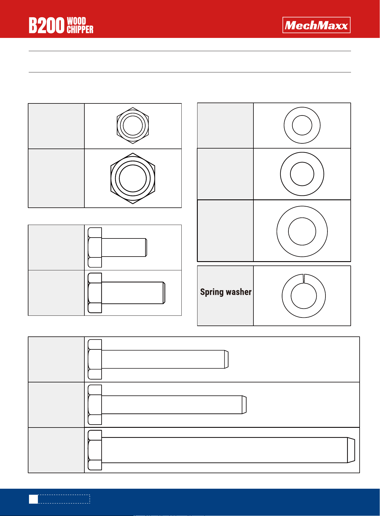
TO-SCALE HARDWARE
TO-SCALE HARDWARE
10
Hardware graphics are printed at 1:1 scale for ease of identification. Simply place the hardware over the image in the
tables to verify it is the correct size.
M10 X 25mm
Hex bolt
8X
M12 X 35mm
Hex bolt
8X
M10 X 70mm
Hex bolt
3X
M10 X 80mm
Hex bolt
3X
M14 X 140mm
Hex bolt
2X
10
Flat washer
17X
12
Flat washer
8X
8X
14
12
Flat washer
2X
15X
nut M10
Hex lock
2X
nut M14
Hex lock
www.mechmaxx.com
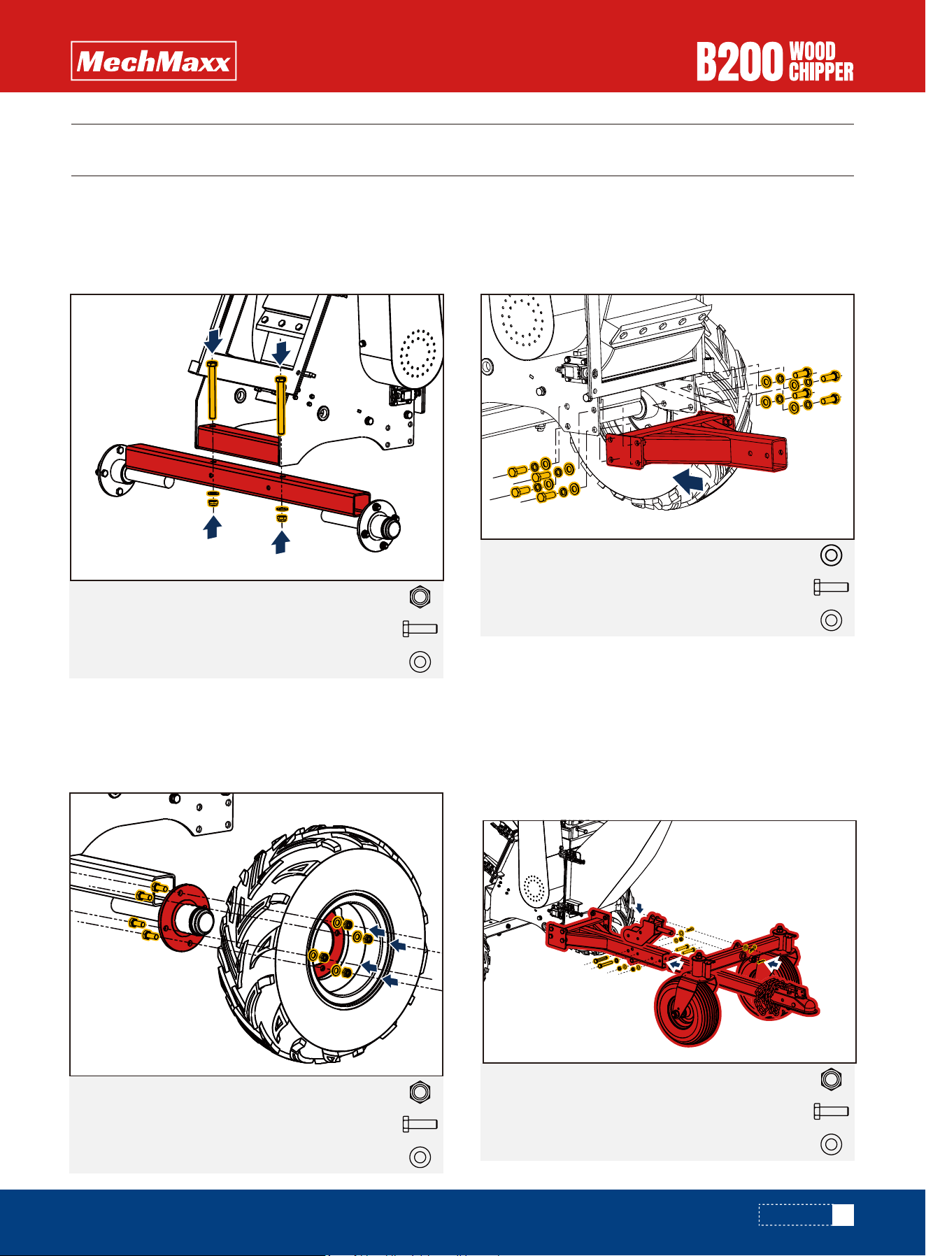
ASSEMBLY
ASSEMBLY
Attach the wheel axle to the cutter base using M14 x 140
hex bolts, 14 mm flat washers, and M14 lock nuts (see
Figure 1).
Attach the wheels to the wheel axles using M10 x 25 hex
bolts, M10 lock nuts, and M10 flat washers (See Figure
2).
Attach the tower bar mount to the base frame with
M12x35 hex bolts, 12 mm spring washers and 12 mm flat
washers (see Figure 3).
11
Hex lock nut M142X
Hex lock nut M108X
Hex bolt M14 X 140mm
Flat washer 14
2X
2X
Hex bolt M12 X 35mm
Flat washer 12
8X
8X
Hex lock nut M103X
Hex bolt M10 X 70mm
Flat washer 10
3X
5X
Hex bolt M10 X 25mm
Flat washer 10
8X
8X
Figure 1
Figure 2
Figure 3
Spring washer 128X
Axle
Wheels
Tower bar mount
Tow bar and Guiding wheel
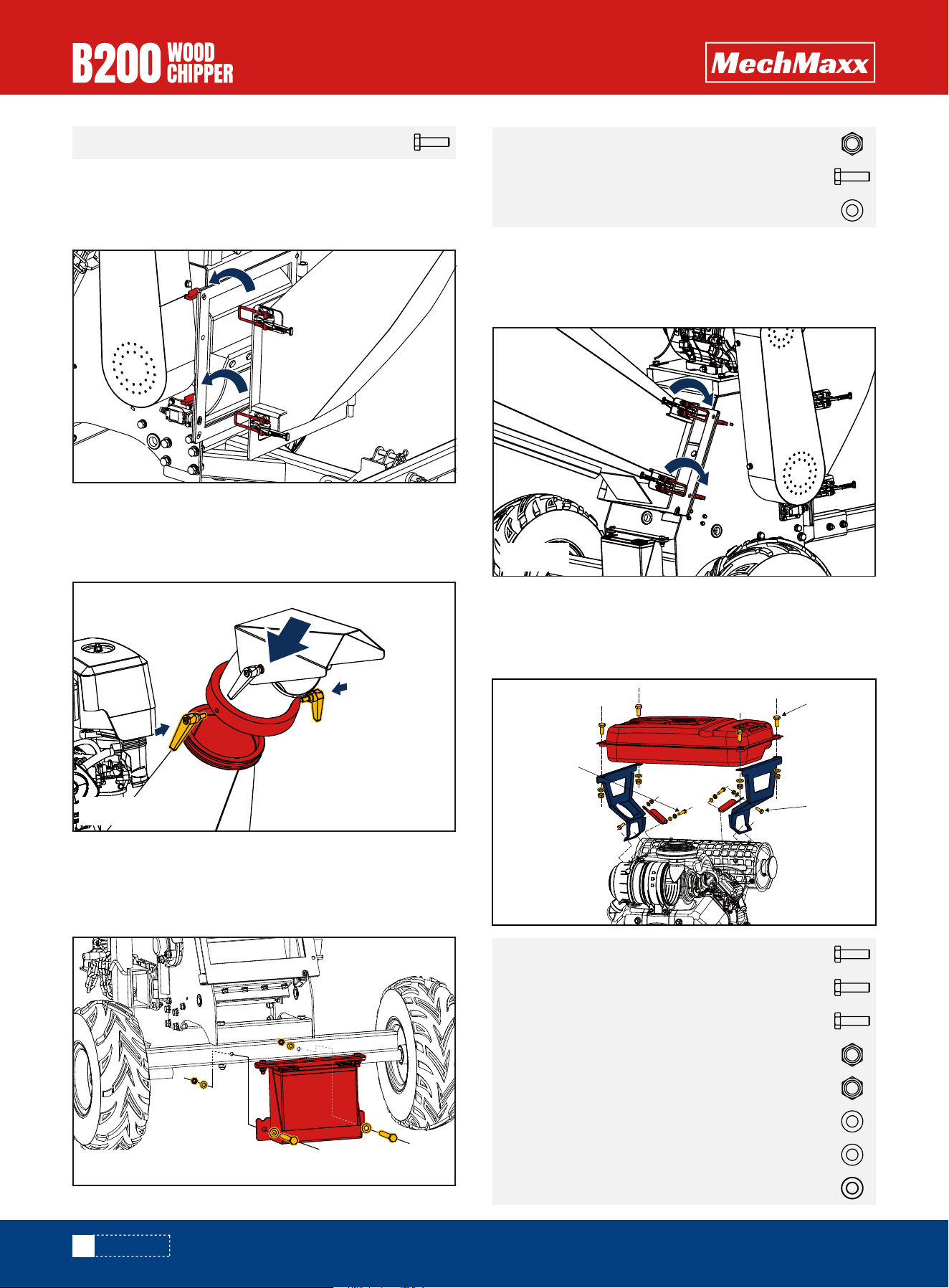
Figure 4
www.mechmaxx.com
Attach the tow bar to the tow bar mounts with M10x70
hex bolts, M10 lock nuts, and flat washer 10 (See Figure
4).
Attach the module to the tow bar mounts with M10x80
hex bolts and pin R 12x25 (See Figure 4).
Attach the wheels to the module with split pin 5x32 (See
Figure 4).
12
Install the fuel tank assembly onto the engine (see Figure
9).
ASSEMBLY
Hex bolt M10 X 80mm
1X
Hex lock nut M102X
Hex bolt M10 X 80mm
Flat washer 10
2X
4X
Hex lock nut M84X
Hex lock nut M62X
Hex bolt M8 X 30mm
Flat washer 6
4X
Hex bolt M6 X 16mm2X
Hex bolt M8 X 16mm2X
2X
Flat washer 8
6X
Spring washer 82X
Lower expulsion chute
360 degree upper expulsion chute
Battery
Tank
Figure 5
Figure 6
Figure 8
Figure 9
Figure 7
M8*30
M6*16
M8*16
www.mechmaxx.com
Infeed chute
Attach the lower expulsion chute to the cutter base using
two lock catches (See Figure 5).
Attach the upper expulsion chute to the lower expulsion
chute with an adjustable locking handle (See Figure 6).
Attach the feeding chute to the cutter base with two lock
catches (See Figure 8).
Attach the battery box to the wheel axle with M10x80 hex
bolts, M10 lock nuts, and flat washer 10 (See Figure 7).
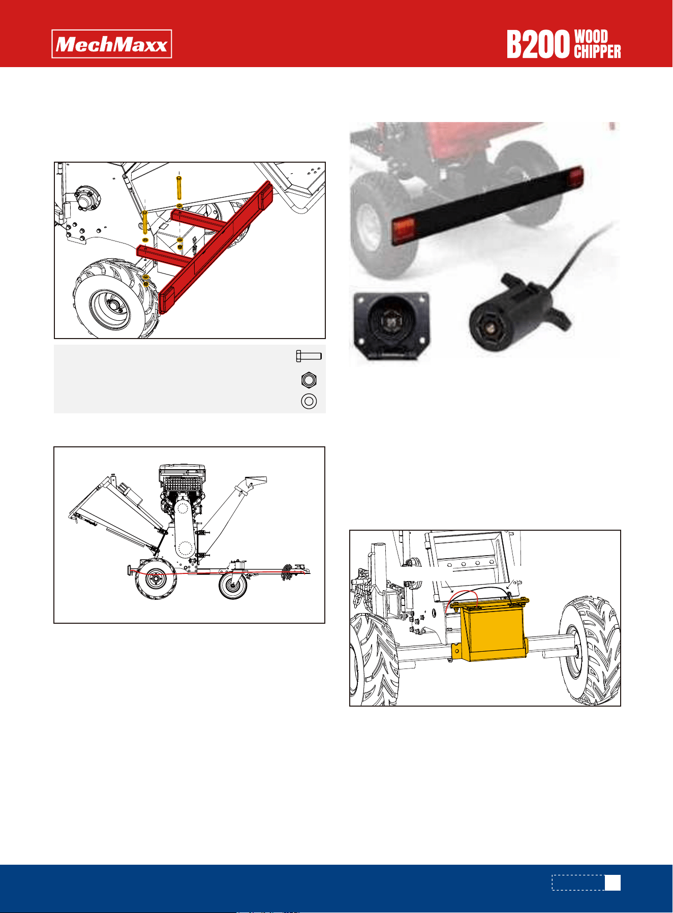
13
ASSEMBLY
Hex lock nut M122X
Flat washer 12
Hex bolt M12 X 120mm2X
4X
Attach the taillights to the shaft using M12x120 hex
bolts, M12 hex lock nuts, and 12 flat washers (see Figure
10).
The B200 is equipped with a tail light, and the trailer has
an American seven-pin plug on one side. The plug can be
connected to the towing vehicle, allowing the B200's tail
light to synchronize with the vehicle's braking and turning
signals.
Tail Light voltage:12V
Material:LED
Tail Light
Taillight line
Tail Light and Plug
Battery wire
Figure 10
Red wire
Black wire
www.mechmaxx.com
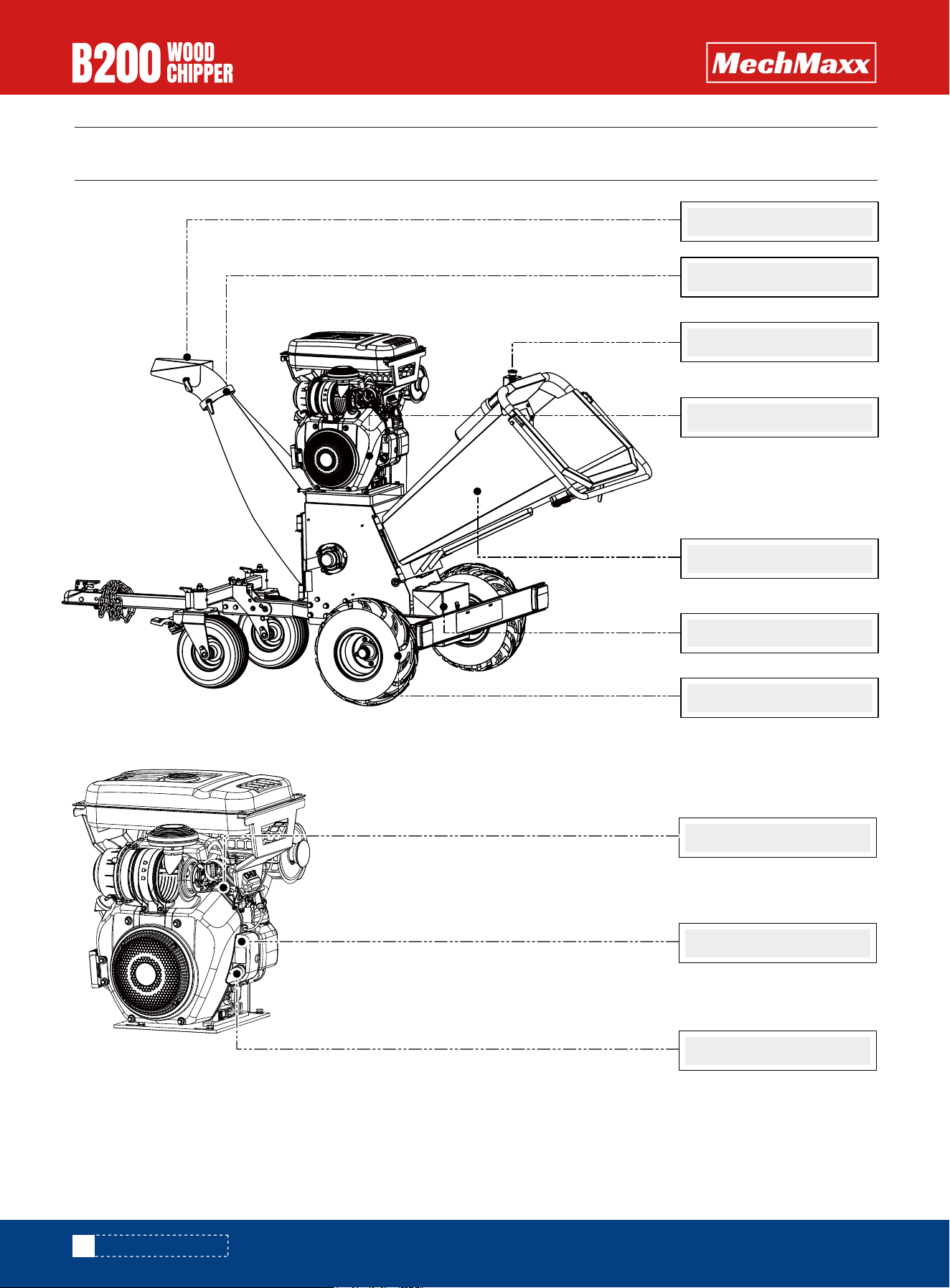
KNOW YOUR MACHINE
KNOW YOUR MACHINE
14
Deflector
Deflector Lever
Engine
Emergency Stop
Battery
Wheels
Feed chute
Choke Control
E-start
Throttle Control
www.mechmaxx.com
15
OPERATION
OPERATION
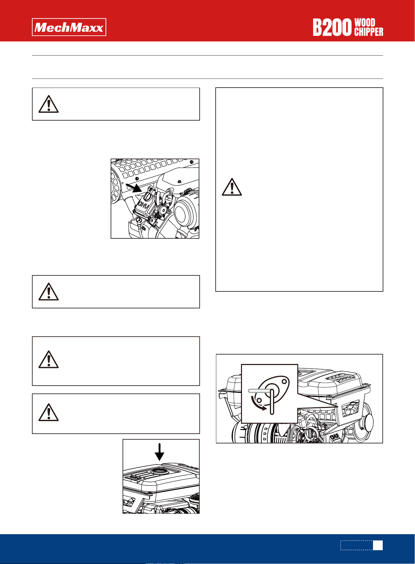
3. Using a funnel, add oil up to the FULL mark on the
dipstick. (See engine manual for oil capacity, oil recom-
mendation, and location of fill cap.).
1. The engine must be off and
allowed to cool at least two
minutes before adding fuel.
2. Remove the fuel filler cap
and fill the tank. (See engine
manual for fuel capacity, fuel
recommendation, and location
of fuel cap.)
The engine is shipped without oil. Do not
start the engine before adding oil.
DO NOT OVERFILL. Check engine oil level
daily and add as needed.
This equipment and/or its engine may
include evaporative emissions control
system components, required to meet
EPA and/or CARB regulations, that will
only function properly when the fuel tank
has been filled to the recommended level.
Overfilling may cause permanent damage
to evaporative emissions control system
components. Filling to the recommended
level ensures a vapor gap required to
allow for fuel expansion. Pay close atten-
tion while filling the fuel tank to ensure
that the recommended fuel level inside
the tank is not exceeded. Use a portable
gasoline container with an appropriately
sized dispensing spout when filling the
tank. Do not use a funnel or other device
that obstructs the view of the tank filling
process.
Gasoline is highly flammable and explo-
sive. You can be burned or seriously
injured when handling fuel. Use extreme
care when handling gasoline.
Fill the fuel tank outdoors, never indoors.
Gasoline vapors can ignite if they collect
inside an enclosure. Explosion can result.
ADD OIL TO ENGINE
ADD GASOLINE TO ENGINE
1. Make sure the wood chipper is on a flat, level surface.
2. Remove the oil fill cap/
dipstick to add oil.
3. Reinstall the fuel cap and tighten. Always clean up
spilled fuel.
IMPORTANT:DO NOT OVERFILL!
1. Open the oil pipe switch under the fuel tank.
STARTING ENGINE
ON
OFF
www.mechmaxx.com
16
OPERATION
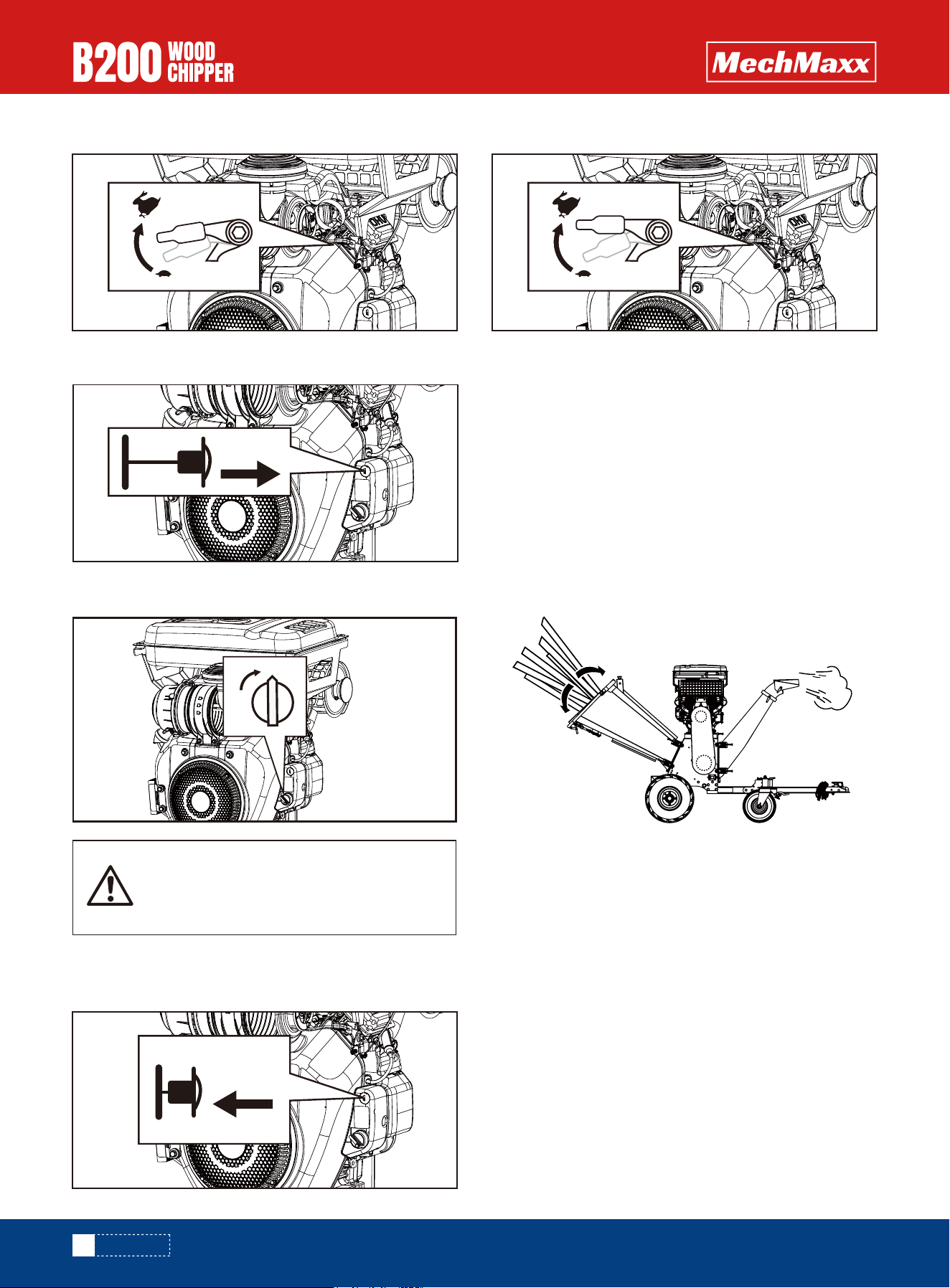
When starting the machine for the first
time, you need to start it several times
when starting the key.
3.Pull the throttle lever out and move it to the off position.
5.Push the throttle lever in and move it to the closed
position.
4. Move the engine switch to the ON position.
6. Move the throttle lever slightly to the FAST speed.
2. Move the throttle slightly.
ON
OFF
OPEN
CLOSE
www.mechmaxx.com
The wood chipper can process a wide variety of dry and
green organic materials, including branches, stalks, vines,
leaves, roots, and vegetable matter. The maximum capac-
ity is 8-inch diameter branches, though this may vary
depending on the type and hardness of the wood. Rotating
the branch as you feed it into the machine can improve
performance.
After the engine warms up, pull the throttle lever to accel-
erate engine speed.
OPERATING
Feed limbs or branches through cut-end first, leaving the
bushy head on. This helps guide the limb down the feed
hopper and reduces spinning and bouncing of small pieces
back up the feed hopper. Some side branches may require
pre-cutting so that they self-feed more efficiently.
It is always advisable to process freshly cut materials, as
wooden branches become springy and dull knives more
quickly when dried out.
While operating the machine, keep a wooden stick handy,
approximately 1 inch in diameter by 2 feet long. This stick
will be useful to push in short, brushy and very leafy mate-
rials and keep the feed hopper clear.
17
OPERATION
www.mechmaxx.com
Do not force material into the machine. If it does not chip
well, the chipper knives may need sharpening or to be
replaced, or the gap between the knives and the wear
plate needs adjusting.
Do not overload the machine by feeding too much material
in to the feed hopper at one time. If you hear the speed of
the engine decreasing, immediately stop feeding material
in to the machine. Do not resume feeding material into the
machine until the engine has returned to full speed.
The wood chipper can clog up with soft, wet, or fibrous
materials. However, if you feed soft materials intermit-
tently with branches, there should be no problem, as the
wood chipper tends to clean out any residue left in the
machine.
If any stringy material wraps around the rotor shaft,
remove it before it works its way into the bearing.
If the wood chipper stalls due to overloading or clogging,
turn off the engine switch and wait until the cutting disk
is completely stopped and the belt drive is disengaged.
Allow the engine to completely cool and switch the engine
to off. Open the housing cover to clear and remove all the
materials from the housing. Lock the housing cover,
switch the engine to the on position, and start the
machine again to resume operation.
As the discharge material plies up, move the chipper away
from the pile. This will keep the material from backing up
the discharge chute. Do not position the deflector
vertically, as this will reduce the airflow, impeding the
discharge and causing blockage.
Make sure the machine is level and stable
to avoid unnecessary vibrations.
Do not open the housing cover unless the
engine and cutting disk are completely
stopped and the belt drive is disengaged.
To shut down the machine, move the
throttle control lever to idle speed, turn
the engine switch to the OFF position, and
it will gradually come to a standstill.
Set the throttle control lever to the SLOW position to
reduce stress on the engine when chipping is not being
performed. Lowering the engine speed will help extend the
life of the engine, as well as conserve fuel and reduce
noise level.
IDLE SPEED
To stop the engine in an emergency, simply turn the
engine switch to the OFF position. Under normal condi-
tions, use the following procedure:
Your wood chipper is equipped with two large pneumatic
wheels for easy maneuverability. To move the unit, grip
the handles and tilt the wood chipper slightly, ensuring
that the oil tank cover is securely tightened beforehand.
Wait until the machine completely stops. Allow the
engine to completely cool. Then clean out the interior of
the machine and its discharge chute.
Sudden stopping at a high speed under a
heavy load is not recommended. Engine
damage may result.
Do not move the choke control to CLOSE
to stop the engine. Backfire or engine
damage may occur.
Do not disengage the belt drive with the
machine running. This will cause friction
and vibration on the belt drive.
STOP ENGINE
1. Move the throttle lever to the SLOW ( ) position.
2. Let the engine idle for one or two minutes.
3. Turn the engine switch to the OFF position.
4. Turn the fuel valve lever to the OFF ( ) position.
TRANSPORTING
18
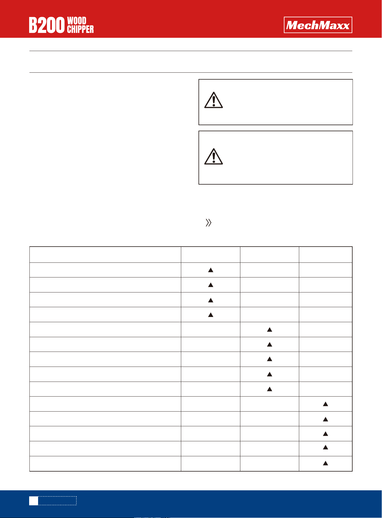
MAINTENANCE
Before each use
Procedure
Every 8-10 Hours Every 40 Hours
Check engine oil level
Check general equipment condition
Check that cutting disk turns freely (with a long stick only)
Visually inspect knife for damage
Check knife and wear plate for sharpness
Check knife and wear plate attachment screws
Check for any loose nut and bolts
Check knife to wear plate gap
Check belt tension and condition
1 time 1 hour
st
1 time 5 hours
st
Check tire pressure
Change engine oil
Inspect or replace drive belt
Inspect or replace spark plug
Inspect or replace air filter and precleaner
www.mechmaxx.com
MAINTENANCE
2. Keep the engine's throttle lever in its SLOW position
and remove the spark plug wire from the spark plug and
secure.
3. Inspect the general condition of the wood chipper.
Check for loose screws, misalignment or binding of
moving parts, cracked or broken parts, and any other
condition that may affect its safe operation.
4. Remove all debris from the Wood chipper with a soft
brush, vacuum, or compressed air. Then use a premium
quality lightweight machine oil to lubricate all moving
parts.
The service intervals shown are the maximum
under normal operating conditions. Increase
frequencies under extremely dirty or dusty condi-
tions.
5. Replace the spark plug wire.
Maintaining your Wood chipper will ensure long life to the
machine and its components.
Never use a pressure washer to clean your
Wood chipper. Water can penetrate tight
areas of the unit and cause damage to
spindles, pulleys, bearings, or the engine.
Shut down the engine, wait for all moving
parts to come to a complete stop, remove
the spark plug wire, and then wait five
minutes before performing maintenance
on the chipper.
PREVENTIVE MAINTENANCE
1. Turn off the engine. The engine must be cool.
REGULAR MAINTENANCE CHECKLIST
19
MAINTENANCE
www.mechmaxx.com
Routinely inspect both the knives (for sharpness) and the
wear plate (for edge condition) to ensure that your wood
chipper is operating at full efficiency. Using dull knives or
a rounded wear plate will decrease performance and
cause excessive vibration that will damage the machine
and make chipping difficult for the operator.
KNIFE AND WEAR PLATE INSPECTION
If the machine's cutting disk strikes a foreign
object, or if the machine begins to make an
unusual noise or vibrates excessively, immedi-
ately shut off the engine. Allow the cutting disk
to come to a complete stop. Switch the engine to
"off" to avoid any accidental start. Then perform
the following steps:
Inspect for damage.
Repair or replace damaged parts.
Check for any loose parts and tighten to ensure
continued safe operation.
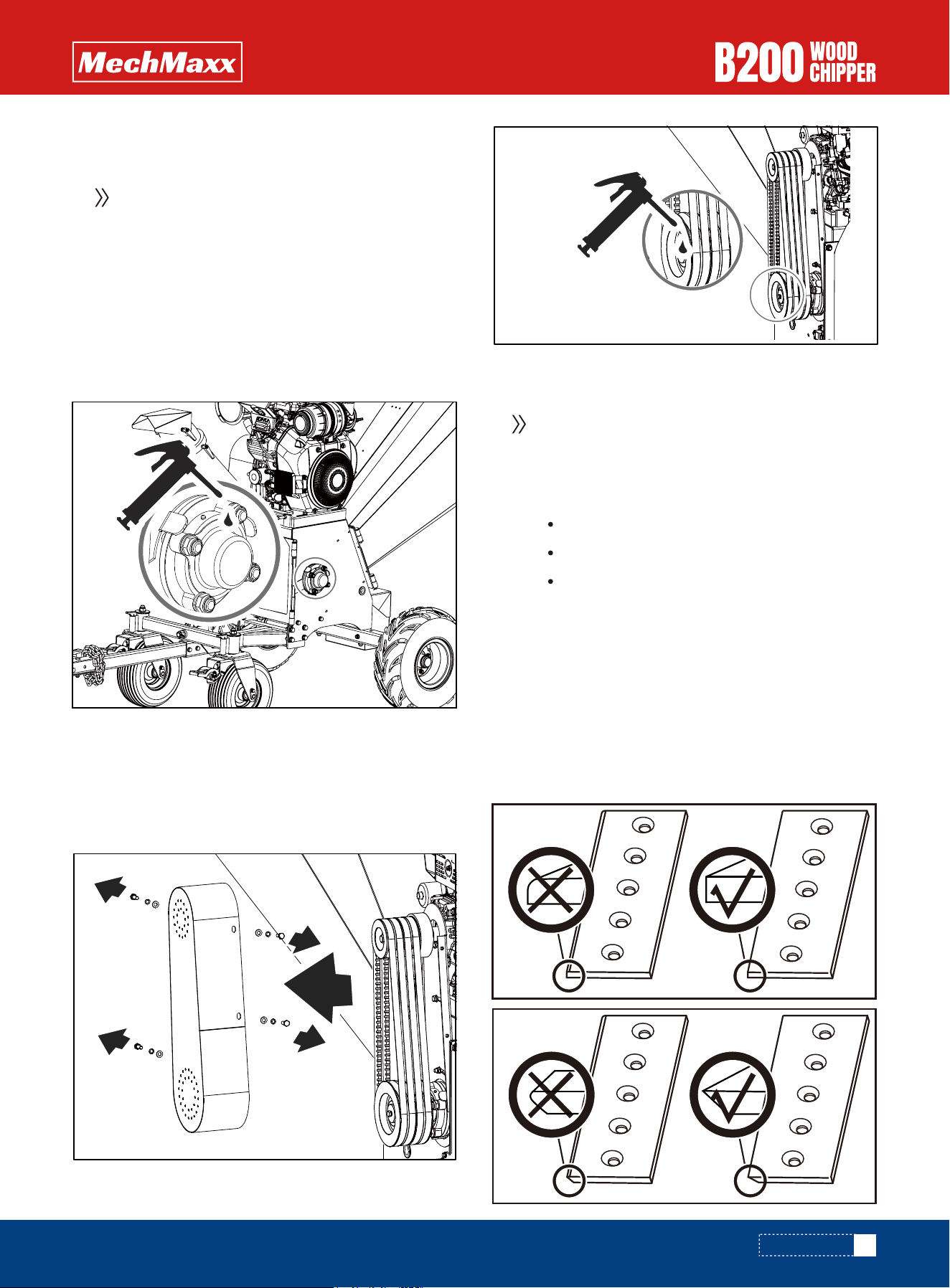
There are two bearings, one outside and the
other inside the housing . The bearings are
greased when they are new, but it is recommend-
ed to grease them after a couple hours of use.
One or two pumps is sufficient. Be careful not to
over grease. Over lubrication can damage the
bearings.
Grease the outside bearing
1. Open the plastic oil plug.
2. Grease the outside bearing through the filling hole.
3. Close the plastic oil plug.
1. Loosen the lock nut which holds the discharge chute
on the machine.
2. Slide down the fixing plate under the lock nut.
Grease the inside bearing
3. Open, then grease the inside bearing.
20
MAINTENANCE
www.mechmaxx.com
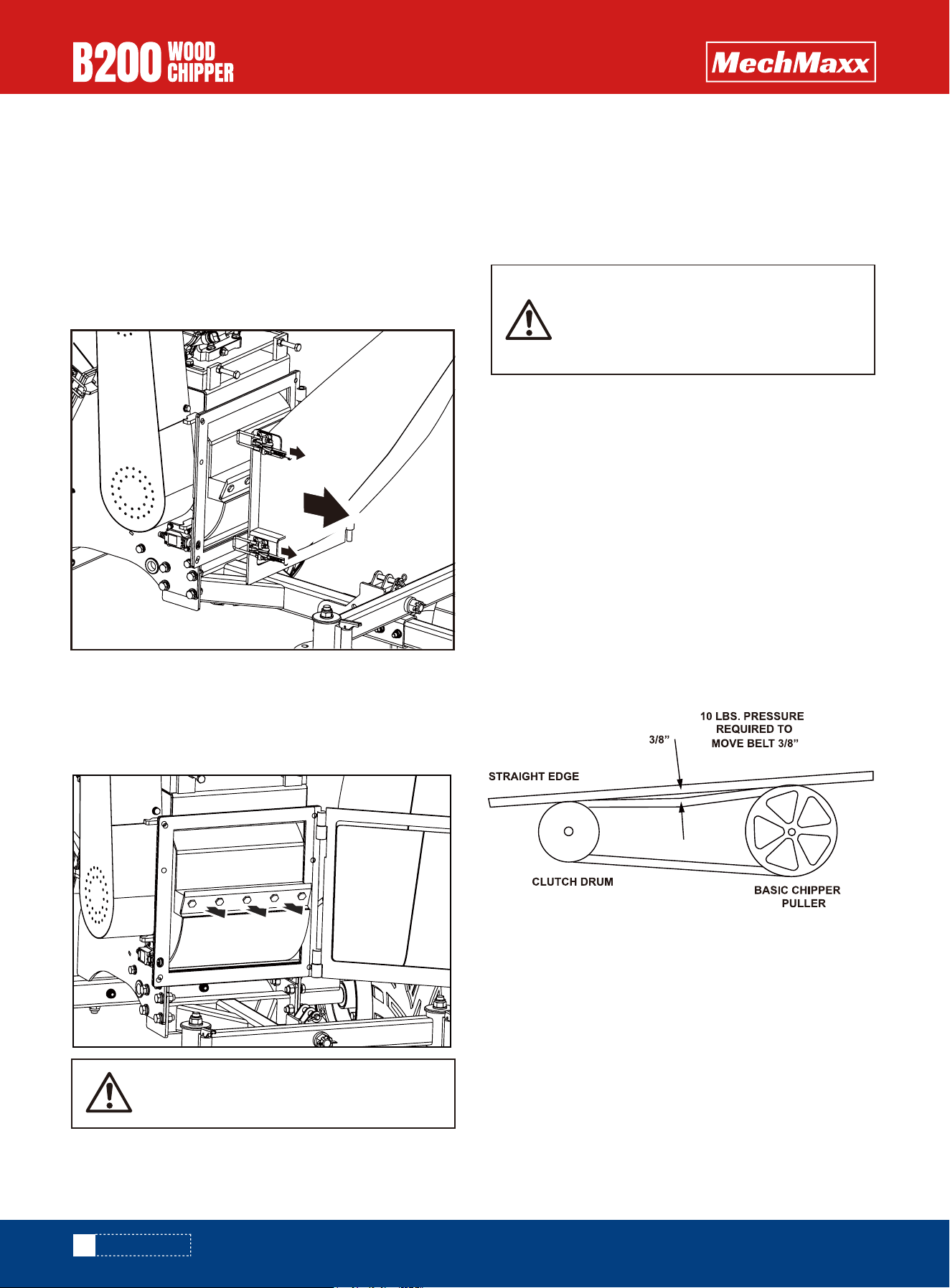
The clearance between the knives and wear plate should
be approximately 0.04 inch at the position of closest to
the rotor shaft and 0.12 inch at the position of farthest to
the rotor shaft. They are tapered out slightly to allow for a
small amount of movement in the cutting disk as it bites
into the wood.
Make sure that all locknuts are tightened properly. Then
turn the cutting disk with a long wooden stick to make
sure it rotates freely.
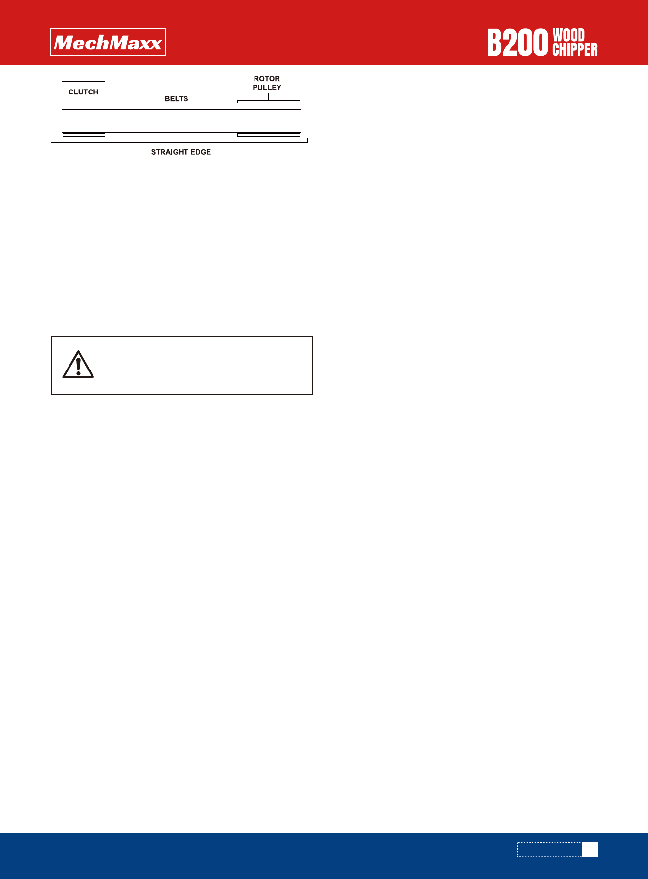
BELT ADJUSTMENT
fig.1
The belt on your chipper should deflect 3/8 in. under 10 lb
of pressure, as shown in Figure 1 below.
If it does not, adjust the belt tension according to the
following instructions.
1.
2.
3.
4.
5.
6.
Remove belt guard.
Loosen engine bolts.
Tighten or loosen the nut until you have the correct
tension as shown in fig. 1.
Retighten engine bolts.
Check alignment of the clutch with the drive pulley by
placing a straight edge across both faces as shown in
fig. 2. If adjustment is necessary, correct alignment
by moving rotor pulley in or out on the rotor shaft. Do
not make adjustment by moving the clutch on the
engine shaft.
Replace belt guard.
If the cutting disk surface is not cleaned
properly and the knives are not mounted
flush on the cutting disk, the knives could
crack when the hardware is tightened.
5. Remove the dull or damaged knives and visually
inspect the cutting disk slot and knives mounting area.
Make sure they are clean and that the placement knives
will be able to mount flush against the cutting disk.
Remount new or sharpened knives with the knife edges
facing up.
1. Remove the feed hopper.
Be careful and wear gloves when working
near the knives.
3. Rotate the cutting disc until the blade can be seen
from the feed hopper side.
2. Remove the discharge chute.
4. Remove the bolts, nuts that fix the blade.
KNIFE REMOVAL AND REPLACEMENT
This Wood chipper is equipped with two chipper knives
mounted on the cutting disk. When the knives get dull or
show visible nicks, the machine will lose its self- feeding
action and the material has to be pushed in. Often it
comes out in long strips. Replace the knives by following
steps.
21
MAINTENANCE
fig.2
www.mechmaxx.com
1.
2.
3.
NOTE: Check and re-tighten belts after
initial break-in period, one hour of use.
BELT REPLACEMENT
To replace the belt, follow the belt adjustment direc-
tions above.
After loosening the engine bolts, remove the old belts
and replace them with new ones. Always replace both
belts, as they come in a matched set. This is required
for proper operation.
Set the belt tension and alignment according to the
instructions above.
CENTRIFUGAL CLUTCH TECH TIPS
The shoes and springs on the clutch are normal wear
items. If you notice decreased performance of the clutch,
they should be checked and replaced if necessary.
The clutch on your machine is designed for rugged,
dependable service. However, it is important to under-
stand the limitations of a clutch. A clutch is designed to
provide load-free starting of the engine and allow slippage
under excessive overloading of the driven application.
These features help protect the engine from damage,
such as broken crankshafts and starters.
The clutch obtains its power from engine RPMs. The lower
the engagement speed and the higher the maintained
engine speed, the more torque the clutch can transfer to
the driven unit. Do not operate at less than full RPMs.
At engine start-up, your chipper's engine operates under
no load until approximately 1,000–1,200 RPMs, at which
point the centrifugal clutch engages and begins driving
the rotor.
The proper rotor speed is 2,200 RPM ± 200 RPM when the
engine is at full RPM.
Do not tamper with the engine's governor setting. The
governor controls the maximum safe operating speed and
protects the engine. Over-speeding the engine is danger-
ous and will cause damage to the engine and other
moving parts of the machine. See your authorized dealer
for engine governor adjustments.
Become familiar with successful operating conditions
and avoid those that can overload or damage the
machine.
Do not overload or attempt to chip material beyond the
manufacturer's recommendation. Personal injury or
machine damage could result.
Learn to recognize the sound of the machine when it is
overloaded. If the machine becomes jammed due to
overloading or any other cause, stop the machine immedi-
ately.
If the machine jams and the engine is not stopped, it can:
Burn the belt.
Ruin the clutch.
Only operator experience will determine how quickly you
can successfully feed limbs into the machine.
Clutch damage can be costly and is not covered under
warranty. For this reason, immediately shut off the
machine if it becomes jammed.
22
STORAGE
www.mechmaxx.com
STORAGE
Remove the spark plug and drain all oil
from the cylinder before attempting to
start the unit after storage.
Do not use strong detergents or petroleum
based cleaners when cleaning plastic
parts. Chemicals can damage plastics.
Do not store your wood chipper with fuel
in a non-ventilated area where fuel fumes
could reach flames, sparks, pilot lights or
any ignition sources.
If your Wood chipper will not be used for more than 30
days, follow the steps below to prepare your unit for
storage:
1. Drain the fuel tank completely. Stale fuel has high
gum content and can clog the carburetor and restrict fuel
flow.
2. Start the engine and allow it to run until it stops. This
ensures no fuel is left in the carburetor and helps prevent
deposits from forming inside, which can damage the
engine.
3. Drain the oil from the engine while it is still warm.
Refill with fresh oil of the grade recommended in the
engine manual.
4. Allow the engine to cool. Remove the spark plug and
put 60 ml of SAE-30 high-quality engine oil into the cylin-
der. Pull the starter rope slowly to distribute the oil.
Replace the spark plug.
5. Use clean cloths to clean off the outside of the Wood
chipper and to keep the air vents free from obstructions.
6. Store your wood chipper in an upright position in a
clean, dry building with good ventilation.
Use only approved fuel containers.

23
TROUBLESHOOTING
www.mechmaxx.com
TROUBLESHOOTING
Remedy
Problem
Cause
Engine fails to start 1. Spark plug wire is disconnected.
2. Out of fuel or stale fuel.
3. Engine and/or Fuel valve is not in
ON position.
4. Choke lever is not in CLOSE position.
5. Blocked fuel line.
6. Fouled spark plug.
7. Engine flooding.
1. Attach spark plug wire securely to
spark plug.
2. Fill with clean, fresh gasoline.
3. Engine and Fuel valve must be in ON
position.
4. Choke lever must be in CLOSE position
for a cold start.
5. Clean fuel line.
6. Clean, adjust gap, or replace.
7. Wait a few minutes to restart, but do
not prime.
Engine runs erratically
1. Connect and tighten spark plug wire.
2. Move choke lever to OPEN position.
3. Clean fuel line. Fill tank with clean,
fresh gasoline.
4. Clear vent.
5. Drain fuel tank. Refill with fresh fuel.
6. Clean or replace air cleaner.
7. Refer to engine manual.
1. Spark plug wire is loose.
2. Unit running with Choke lever in
CLOSE position.
3. Blocked fuel line or stale fuel.
4. Vent plugged.
5. Water or dirt in fuel system.
6. Dirty air cleaner.
7. Improper carburetor adjustment.
Engine overheats 1. Fill crankcase with proper oil.
2. Clean air cleaner.
3. Remove housing and clean.
4. Refer to engine manual.
1. Engine oil level low.
2. Dirty air cleaner.
3. Air flow restricted.
4. Carburetor not adjusted properly.
Chipping action seems
too slow, cutting disk
stalls,or no material
is discharged when
engine is running
1. Run the engine at full throttle.
2. Tighten or replace drive belt.
3. Sharpen or replace knives.
4. Remove any built-up debris and turn
cutting disk with a wooden stick to be
sure it turns freely.
5. Clean out debris.
1. Engine speed is too slow causing
belt to slip.
2. Drive Belt is loose or damaged.
3. Knives are dull or damaged.
4. Cutting disk is jammed by
debris from the feed hopper and
discharge chute.
5. Discharge chute is clogged.

24
TROUBLESHOOTING
www.mechmaxx.com
Remedy
Problem
Cause
The belt frays or rolls
over the pulley
When chipping,
branch seems to
vibrate and move
about excessively with
unusual noise
Chipper Knives are
hitting the wear plate
The machine's wheels
track left or right
while being towed
Low tire pressure.
The gap between the knives and wear
plate is set incorrectly.
Add air to tires.
Adjust the gap.
1.Sharpen or replace knives.
2. Loosen the knife mounting screws, reset
the knives, and tighten the screws.
3. Adjust the gap.
4. Allow unit to clear itself before adding
more material to the hopper.
1. Check drive belts for wear and hard
spots. File off any nicks on the pulley.
2. Replace drive belts.
3. Adjust pulleys.
1. Rotor drive pulley groove may be
nicked.
2. Drive belts may be stretched.
3. Pulleys may be misaligned.
1. Knives are dull or damaged.
2. Knives are not properly seated on
the cutting disk.
3. The gap between the knives and
wear plate is too large.
4. Rotor is overloaded with material.
25
www.mechmaxx.com
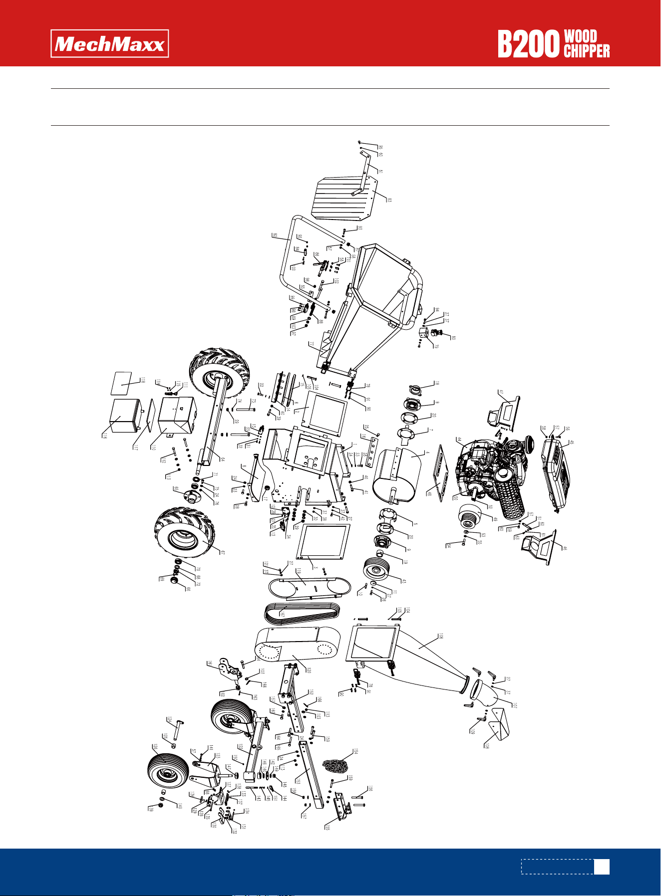
PARTS DIAGRAM
PARTS DIAGRAM

26
www.mechmaxx.com
PARTS LIST
PARTS LIST
1
1
1
1
1
1
1
1
2
1
1
1
2
1
1
2
2
1
1
2
4
5
13
33
10
1
10
8
10
No. QTY
1
2
3
4
5
6
7
8
9
10
11
12
13
14
15
16
17
18
19
20
21
22
23
24
25
26
27
28
29
DESCRIPTION
Blade Housing Weldment
Infeed Tube Rubber Pad
Discharge Tube Rubber Pad
Cutter Drum Weldment
Right Bearing Mounting Plate
Bottom Blade Shim Plate
Left Bearing Mounting Plate
Lower Arc Plate Weldment (Blade Housing)
Inserted Bearing with Mounting Flange
C-type Key B10×8×48
Pulley Retaining Ring
Limit Switch Mounting Plate
Limit Switch
Bottom Blade Adjusting Plate
Fixed Blade
Moving Blade
Double-sided Wire Protector
Bearing End Cover
Pulley Spacer Sleeve
Bearing Mounting Plate
Countersunk Cross Screw M5×14
Hex Head Bolt Full Thread M10×35
Spring Washer 10
Flat Washer Grade C 10
Hex Head Bolt M10×25
Hex Head Bolt Full Thread M8×35
Spring Washer 8
Hex Head Bolt Full Thread M10×30
Thin Nylon Insert Lock Nut M14

27
www.mechmaxx.com
PARTS LIST
8
4
4
4
4
4
4
10
1
4
6
2
1
1
1
1
1
1
1
1
1
2
1
1
1
9
4
12
16
2
9
2
No. QTY
30
31
32
33
34
35
36
37
38
39
40
41
42
43
44
45
46
47
48
49
50
51
52
53
54
55
56
57
58
59
60
61
DESCRIPTION
Small Flat Washer Grade A 14
Hex Head Bolt Full Thread M5×16
Spring Washer 5
Flat Washer Grade C 5
Hex Head Bolt Full Thread M6×16
Spring Washer 6
Flat Washer Grade C 6
Flat Washer 8
Thin Nylon Insert Lock Nut M8
Hex Socket Cap Screw M10×60
Hex Nut Type 1 M10
Hex Head Bolt Full Thread M10×60
Hex Head Bolt M8×25
Large Pulley 4SPA φ200
Engine
Fumigation Fuel Tank 18L
Front Fuel Tank Support
Rear Fuel Tank Support
Engine Mounting Plate Weldment
Centrifugal Clutch
Engine Shaft Spacer φ35×φ29×15
Fuel Tank Diagonal Brace
Engine Shaft Key
Engine End Plate
Hex Head Bolt 7/16–20
Spring Washer 12
Hex Head Bolt M8×30
Flat Washer 8
Hex Lock Nut M8
Hex Head Bolt Full Thread M8×16
Spring Washer 8
Flat Washer 6

28
www.mechmaxx.com
PARTS LIST
2
2
1
2
2
2
2
2
4
2
2
2
2
8
8
1
4
1
1
1
1
1
2
1
1
2
2
1
16
16
2
2
No. QTY
62
63
64
65
66
67
68
69
70
71
72
73
74
75
76
77
78
79
80
81
82
83
84
85
86
87
88
89
90
91
92
93
DESCRIPTION
Thin Nylon Insert Lock Nut M6
Hex Head Bolt Full Thread M6×16
Axle Weldment
Wheel Flange Weldment
Rear Axle End Cap
Wheel Assembly 19×7–8
Small Flat Washer Grade A 24
Cotter Pin 4×45
Deep Groove Ball Bearing with Dust Covers on Both Sides
Inner Skeleton Oil Seal with Secondary Lip
Slotted Thin Hex Nut Grade A/B M24
Hex Head Bolt M14×140
Flat Washer Grade C 14
Hex Head Bolt Full Thread M10×25
Nylon Insert Lock Nut Type 1 M10
Infeed Tube Weldment
Latch Assembly
Emergency Stop Box Weldment
Emergency Stop Switch
Infeed Tube Baffle Mounting Plate
Press Rod Weldment
Infeed Tube Rubber Baffle
Emergency Stop Link Rod
Emergency Stop Pressure Plate
Toggle Clamp
Round Tube Plug φ25
Return Spring φ16×φ1.5×115
Limit Switch
Hex Socket Button Head Screw M6×16
Thin Nylon Insert Lock Nut M6
Nylon Insert Lock Nut M6
Reamed Hex Head Bolt M8×45

29
www.mechmaxx.com
PARTS LIST
2
5
1
4
4
4
2
4
2
4
4
4
1
1
1
4
1
1
2
6
2
2
1
1
1
1
1
4
1
2
2
4
No. QTY
94
95
96
97
98
99
100
101
102
103
104
105
106
107
108
109
110
111
112
113
114
115
116
117
118
119
120
121
122
123
124
125
DESCRIPTION
Hex Head Bolt Full Thread M8×16
Hex Head Bolt Full Thread M8×20
Hex Lock Nut M10
Nylon Insert Lock Nut M12
Spring Washer 5
Cross Pan Head Screw M5×16
Hex Head Bolt Full Thread M6×25
Hex Socket Button Head Screw M8×20
Hex Head Bolt M12×110
Flat Washer 12
Pin Shaft Type B φ12×70
Cotter Pin 3.2×22
Lower Discharge Outlet Weldment
Upper Discharge Tube Weldment
Discharge Guide Plate
Adjustable Positioning Handle – External Thread M8×15
Box Body Weldment
Latch 4001 Assembly
Hex Head Bolt M10×80
Thin Nylon Insert Lock Nut M10
Countersunk Cross Screw M4×10
Thin Hex Lock Nut M4
Battery
Battery Top Pad
Battery Side Plate
Belt Guard Base Plate Weldment
Integrated Belt Guard
Hex Head Bolt Full Thread M8×20
Steering Axle Beam Weldment
Steering Bracket Weldment
Caster Axle Weldment
Caster Spacer Sleeve

30
www.mechmaxx.com
PARTS LIST
2
2
2
4
2
2
4
4
2
2
2
2
8
2
4
2
2
2
2
2
2
2
2
2
2
2
1
1
1
1
2
10
No. QTY
126
127
128
129
130
131
132
133
134
135
136
137
138
139
140
141
142
143
144
145
146
147
148
149
150
151
152
153
154
155
156
157
DESCRIPTION
Wheel 13×5.00–6
Brake Base Plate
Brake Pressure Plate
Thin Hex Nut M10
Brake Parking Plate
Brake Release Plate
Brake Link Plate
Shoulder Screw (Socket Cap) φ6×85–M5
Shoulder Screw (Socket Cap) φ6×65–M5
Shoulder Screw (Socket Cap) φ6×75–M5
Flat Head Bolt M10×22
Brake Spring φ3×φ14×7
Thin Nylon Insert Lock Nut M5
Thin Nylon Insert Lock Nut M20
Flat Washer 20
Hex Head Bolt Full Thread M8×25
Stamped End Cover
Inner Pin Shaft
Over-center Cam Plate
Compression Spring for Pin
Double-row Angular Contact Bearing
Tapered Roller Bearing
Thin Nylon Insert Lock Nut M16
Flat Washer 16
Straight Grease Fitting M6
Heavy-duty Slotted Spring Pin 4.5×16-A
Trailer Hitch Mount Weldment
Trailer Hitch Weldment
Chain
Trailer Coupler
Hex Head Bolt M12×80
Flat Washer Grade C 12

31
www.mechmaxx.com
PARTS LIST
2
3
8
1
1
1
2
1
2
4
No. QTY
158
159
160
161
162
163
164
165
166
167
DESCRIPTION
Thin Nylon Insert Lock Nut M12
Hex Head Bolt M10×70
Hex Head Bolt Full Thread M12×35
Folding Leg Pivot Shaft Weldment
Slotted Thin Hex Nut Fine Thread M20×1.5
Cotter Pin 5×32
Pin Shaft Type B 12×80
Hex Head Bolt M10×80
R-clip Pin O3×45
Belt AV13×1410 (1360Li)