Operator’s Manual
www.mechmaxx.com
WARRANTY

INTRODUCTION
1
www.mechmaxx.com
INTRODUCTION
Do not start or operate the machine
before you read this manual. Make sure
that you fully understand all the safety,
operation, and maintenance information
before you operate the machine.
Keep this manual with the machine at all
times and available for frequent refer-
ence.
Congratulations on your purchase and welcome to Mech-
Maxx! This manual gives you the necessary information
about your machine so you will be able to use it properly.
The entire manual must be read and understood before
you start using the machine. If any questions should arise
that are not covered by this manual, please contact
MechMaxx.
This machine is designed for certain applications only.
We strongly recommend that this machine is not modied
and/or used for any application other than that for which
it was designed. If you have any questions relative to a
particular application, DO NOT use the machine until you
have rst contacted us to determine if it can or should be
performed on the product.
The Engine Manufacturer is responsible for all engine
related issues with regards to performance, power
rating, specifications, warranty and service. Please refer
to the Engine Manufacturer's owner/operator's manual.
Record the model and serial number as well as date and
place of purchase for future reference. Have this
information available when ordering parts or optional
accessories and when making technical or warranty
inquiries.
This manual is subject to change without notice. For the
most current information, go to Mechmaxx.com.
For available accessories, go to mechmaxx.com.
ENGINE MANUAL
MODEL AND SERIAL NUMBERS

SAFETY
SPECIFICATIONS
TABLE OF CONTENTS
PERSONAL SAFETY
3
4
5
5
7
IMPORTANT SAFETY INFORMATION
8
CONTENTS SUPPLIED
10
10
ASSEMBLY
24
KNOW YOUR MACHINE
25
OPERATION
OVERALL DIMENSIONS
TRANSPORT
30
WIRING DIAGRAM
30
MAINTENANCE
31
PARTS DIAGRAM
33
PARTS LIST
34
HYDRAULIC SCHEMATIC DIAGRAM
44
28
HYDRAULICALLY CONTROLLED CONVEYOR SPEED
29
IDLE SPEED
29
STOP ENGINE
30
TRANSPORT SAFETY
30
TOWING
31
MAINTENANCE PRECAUTIONS
31
HYDRAULIC OIL
31
ENGINE OIL
31
RECOMMENDED FUEL
32
MAINTENANCE INTERVAL CHART
5
UNDERSTAND YOUR MACHINE
CHASSIS ASSEMBLY
10
HITCH COUPLER ASSEMBLY
11
ASSEMBLE TIRES, AXLES AND TAILLIGHTS
12
TRAILER JACK ASSEMBLY
14
TAIL LIGHT CABLE ASSEMBLY
14
BRACKET ASSEMBLY
15
19
CONVEYOR BELT ASSEMBLY
20
ENGINE AND HYDRAULIC TANK ASSEMBLY
21
CONVEYOR BELT AND CHASSIS ASSEMBLY
22
HYDRAULIC SYSTEM ASSEMBLY
25
OPERATING SAFETY
25
ADD OIL TO ENGINE
26
ADD GASOLINE TO ENGINE
26
STARTING ENGINE
27
OPERATING
28HYDRAULIC ADJUSTMENT OF CONVEYOR ANGLE
28HYDRAULIC CONTROL OF THE DIRECTION OF
TRANSMISSION
WORK AREA
5
5
FUEL SAFETY
USES
6
6
MACHINE USE AND CARE
EMERGENCY STOP BUTTON
2
www.mechmaxx.com
TABLE OF CONTENTS

SPECIFICATIONS
Ducar engine 274cc
Sound power level: LWA=108.4dB, K=3dB
Emission sound pressure level: LPA=92.6dB, K=3dB
Engine
Engine Type
Displacement
Start
Conveyor Belt length
Conveyor Belt Wide
Max Discharge Height
Min Discharge Height
Height Adjustment
Drive System
Hydraulic Pump
Hydraulic Fluid Type
Hydraulic Tank Capacity
Hydraulic Oil Filter Fineness
Towing
Maximum Towing Speed
Minimum Height (2.4m):
Maximum Height (4.5m):
Max inclination:
Tires Rims
Tires
Overall Dimensions (LxWxH)
Finish
Weight (N.W./G.W.)
Packing Method
Packing Size
Ducar DH270
Single Cylinder, 4 Stroke, Air-Cooled, OHV
270 cc; 9 hp
Recoil
275.5 in
24.5 in
177 in
94.4 in
Hydraulic
Hydraulic
5.7 GPM Single Stage Pump
AW-46
4.2 gal
10 micron
Tow Bar with 2 in Coupler
45 MPH
Maximum Load ≤ 440 lbs
Maximum Load ≤ 353 lbs
5°
12.9 in
19 in Radial (0. D.)
304x62.4x106.1 in
Powder Coating
1565/1697 lbs
Plywood case
90x38x33 in
Model HC2320
3
www.mechmaxx.com
SPECIFICATIONS
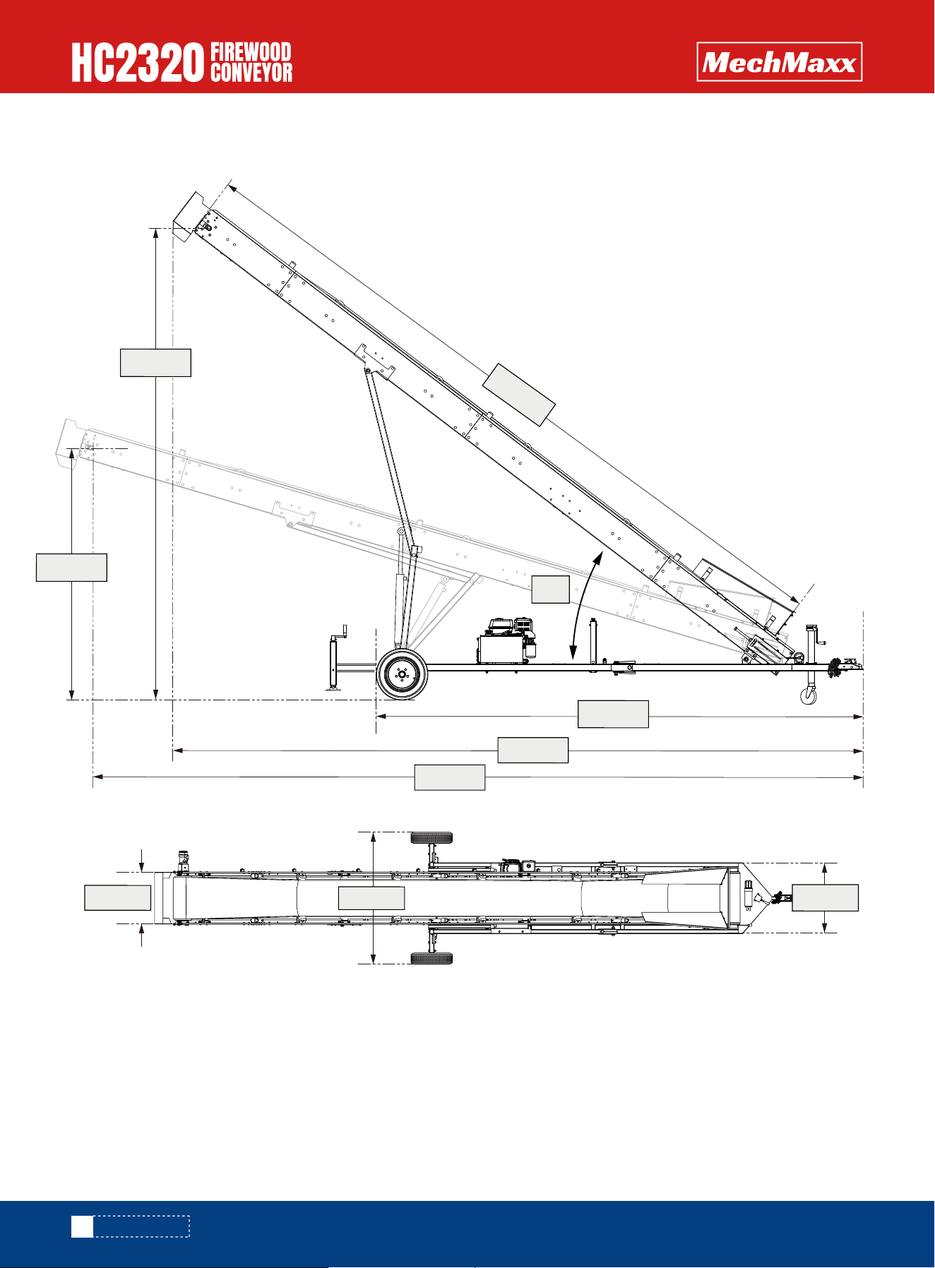
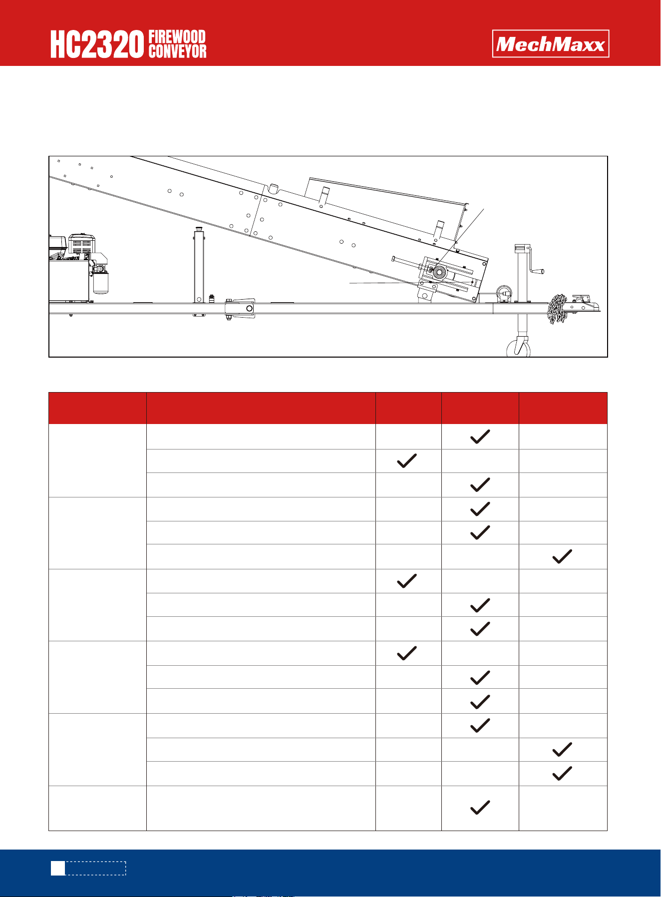
275.5 in
OVERALL DIMENSIONS
177.1 in
94.4 in
24.2 in
62.3 in
183.3 in
37°
259.4 in
304 in
33.4 in
4
www.mechmaxx.com
SPECIFICATIONS

SAFETY
Be thoroughly familiar with the controls and their proper
operation. Know how to stop the machine and disengage
the controls quickly.
Make sure to read and understand all the instructions and
safety precautions as outlined in the Engine Manufactur-
er's Manual. packed separately with your unit. Do not
attempt to operate the machine until you fully understand
how to properly operate and maintain the Engine and how
to avoid accidental injuries and/or property damage.
Read and understand the operator's
manual and labels affixed to the machine.
Learn its application and limitations as
well as the specific potential hazards
peculiar to it.
Never start or run the machine inside a closed area. The
exhaust fumes are dangerous. containing carbon monox-
ide, an odorless and deadly gas. Operate this unit only in a
well ventilated outdoor area.
Never operate the machine without good visibility or light.
Do not turn on, or plug in electrical components near
water exposures or in wet conditions.
Fuel is highly flammable, and its vapors can explode if
ignited. Take precautions when using to reduce the chance
of serious personal injury.
When refilling or draining the fuel tank, use an approved
fuel storage container while in a clean, well-ventilated
outdoor area.
While adding fuel or operating the unit, do not smoke, and
stay away from sparks, open flames, or other sources of
ignition near the area of operation. Never fill the fuel tank .
Keep grounded conductive objects. such as tools, away
from exposed. live electrical parts and connections to
avoid sparking or arcing. These events could ignite fumes
or vapors.
Always stop the engine and allow it ti cool before filling the
fuel tank. Never remove the cap of the fuel tank or add fuel
while the engine is running or when the engine is hot. Do
not operate the machine with known leaks is the fuel
system.
Do not operate the machine while under the influence of
drugs,alcohol, or any medication that could affect your
ability to use it properly.
Dress properly. Wear heavy long pants,boots and gloves.
Do not wear loose clothing. short pants, and jewelry of
any kind. Secure long hair so it is above shoulder level.
Keep your hair. clothing and gloves away from moving
parts. Loose clothes. jewelry or long hair can be caught
in moving parts.
Use safety equipment. Always wear eye protection.
Safety equipment such as a dust mask, hard hat, or
hearing protection used for appropriate conditions will
reduce personal injuries.
Check your machine before starting it. Keep guards in
place and in working order. Make sure all nuts bolts,etc.
are securely tightened.
Never operate the machine when it is in need of repair or
is in poor mechanical condition. Replace damaged, miss-
ing or failed parts before using it. Check for fuel leaks.
Keep the machine in safe working condition.
Never remove or tamper with safety device. Check their
proper operation regularly.
Do not use the machine if the engine's switch does not
turn it on or off. Any gasoline powered machine that can
not be controlled with the engine switch is dangerous and
must be replaced.
Form a habit of checking to see that keys and adjusting
wrenches are removed from machine area before starting
it. A wrench or a key that is left attached to a rotating
part of the machine may result in personal injury.
Stay alert, watch what you are doing and use common
sense when operating the machine.
Do not operate the machine while barefoot or when wear-
ing sandals or similar light weight footwear. Wear
protective footwear that will protect your feet and
improve your footing on slippery surfaces. Keep proper
footing and balance at all times. This enables better
control go the machine in unexpected situations.
Avoid accidental starting. Be sure the engine is off before
transporting the machine or performing any maintenance
or service on the unit. Transporting or performing mainte-
nance or service on a machine with engine on invites
accidents.
Only operate the conveyor when the Undercarriage and
conveyor have been leveled and anchored properly. Do not
operate conveyor when the undercarriage wheels are free
of movement on the ground. Do not operate conveyor
when transporting the equipment.
UNDERSTAND YOUR MACHINE
FUEL SAFETY
WORK AREA
PERSONAL SAFETY
5
www.mechmaxx.com
SAFETY

List of warnings and cautions cannot be all-inclusive. If
situations occur that are not covered by this manual, the
operator must apply common sense and operate this
Firewood Conveyors in a safe manner. Contact the dealers
for assistance in your area.
Loose the fuel tank cap slowly to relieve any pressure in
the tank.
Replace all fuel tank and container caps securely and
wipe up spilled fuel, Never operate the unit without the
fuel cap securely in place.
Avoid creating a source of ignition for spilled fuel. If fuel
is spilled, do not attempt to start the engine but move the
machine away from the area of spillage and avoid creating
any source of ignition until fuel vapors have dissipated.
Store fuel in containers specifically designed and
approved for this purpose.
Store fuel in a cool. well-ventilated area, safely away
from sparks, open flames or other sources of ignition.
Never store fuel or machine with fuel in the tank inside a
building where fumes may reach a spark, open flame, or
other sources of ignition, such as a water heater, furnace,
clothes dryer and the like, Allow the engine to cool before
storing in any enclosure.
Never over fill fuel tank. Fill tank to no more than 1/2 inch
below the bottom of the filler neck to provide space for
expansion as the heat of the engine can cause fuel to
expand.
The conveyor’s purpose is to transport material, not
people. Using the conveyor to transport people is
extremely hazardous and may cause injury or death.
Do not allow anyone to climb on the conveyor or use it as
a ladder to reach higher elevations.
Do not let anyone ride, stand or sit on a running convey-
or.Instability of a conveyor can result from being placed
on dirt, unstable ground or another unstable support.
Weight limitation or load capacities of the conveyor
should be observed carefully.
Position the machine in such a way that it can not move
during maintenance, cleaning, adjustment, assembly of
accessories or spare parts, as well as under storage,
Do not change the engine governor settings or over-speed
the engine. The governor controls the maximum safe
operating speed of the engine.
Do not put hands or feet near rotating parts.
Avoid contact with hot fuel. oil. exhaust fumes and hot
surfaces.
Do not touch the engine or muffler. These parts get
extremely hot from operation. They remain hot for a short
time after you turn off the unit, Allow the engine to cool
before doing maintenance or making adjustments.
If the machine should start to make an unusual noise or
vibration, immediately shut off the engine, disconnect the
spark plug wire, and check for the cause, Unusual noise or
vibration is generally warning of trouble .
Use only attachments and accessories approved by the
manufacturer. Failure to do so can result in personal
injury.
Maintain the machine. Check for misalignment or binding
of moving parts. breakage of parts and any other condi-
tion that may affect the machine's operation. If
damaged. have the machine repaired before use. Many
accidents are caused by poorly maintained equipment.
USES
MACHINE USE AND CARE
6
www.mechmaxx.com
SAFETY

IMPORTANT SAFETY INFORMATION
ALL CAUTIONS AND SAFETY WARNINGS MUST BE FOLLOWED TO AVOID INJURY OR
DAMAGE TO EQUIPMENT.
THIS EQUIPMENT IS TO BE USED ONLY BY TRAINED OPERATORS AND MUST ALWAYS BE
ATTENDED DURING OPERATION.
*Decals are to be replaced if worn or illegible.
This manual contains essential information regarding the safety hazards, operations, and maintenance associated with
this machine. The manual should always remain with the machine, including if it is resold.
7
www.mechmaxx.com
IMPORTANT SAFETY INFORMATION
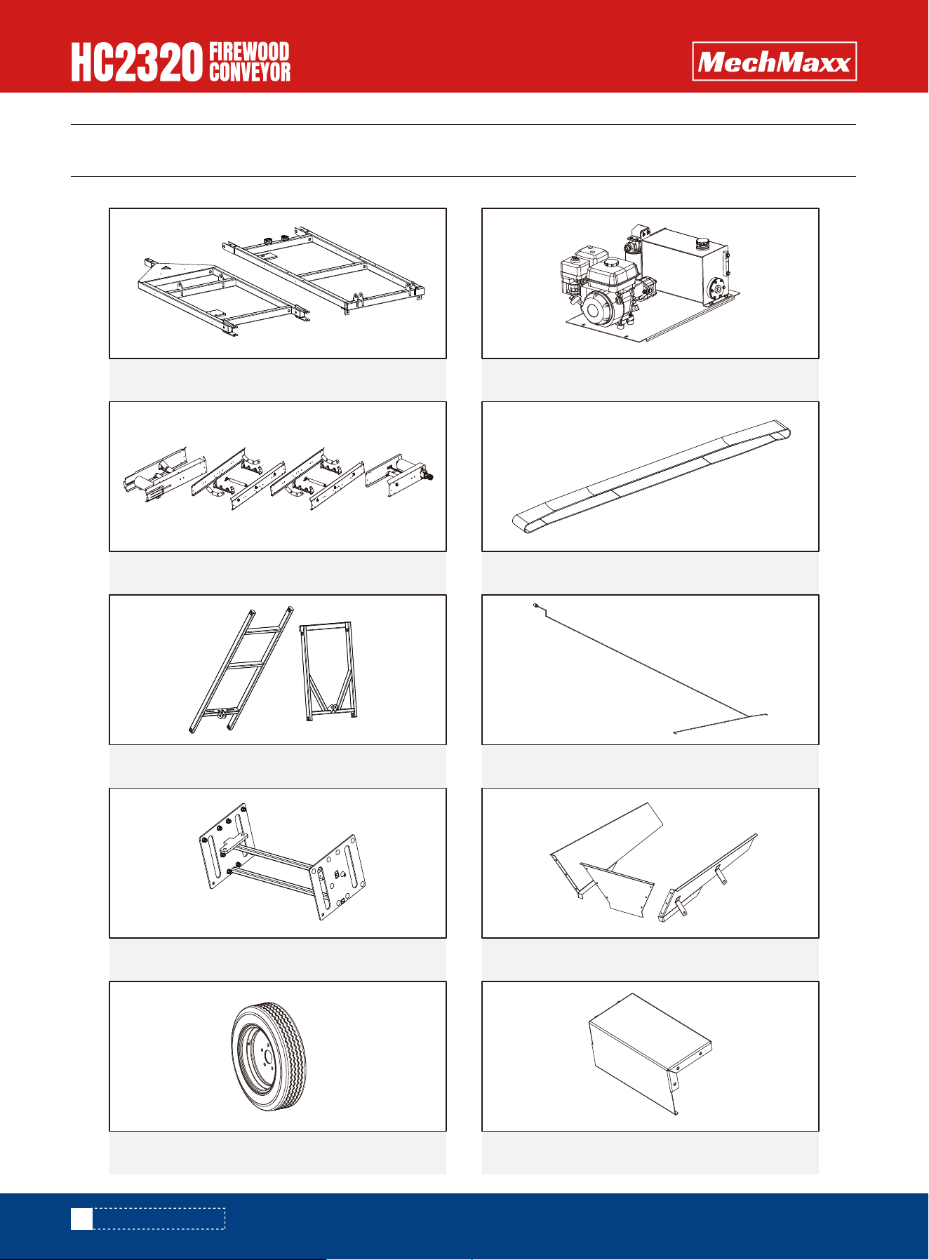
CONTENTS SUPPLIED
Your Firewood Conveyors comes partially assembled and contains the following:
CHASSIS
1x
CHASSIS 2
1x
CONVEYOR BELT
1x
BELT
1x
BRACKET
1x
WIRING HARNESS
1x
CONNECTING PLATE
3x
HOPPER
1x
WHEEL
2x
BOTTOM GUARD
1x
8
www.mechmaxx.com
CONTENTS SUPPLIED
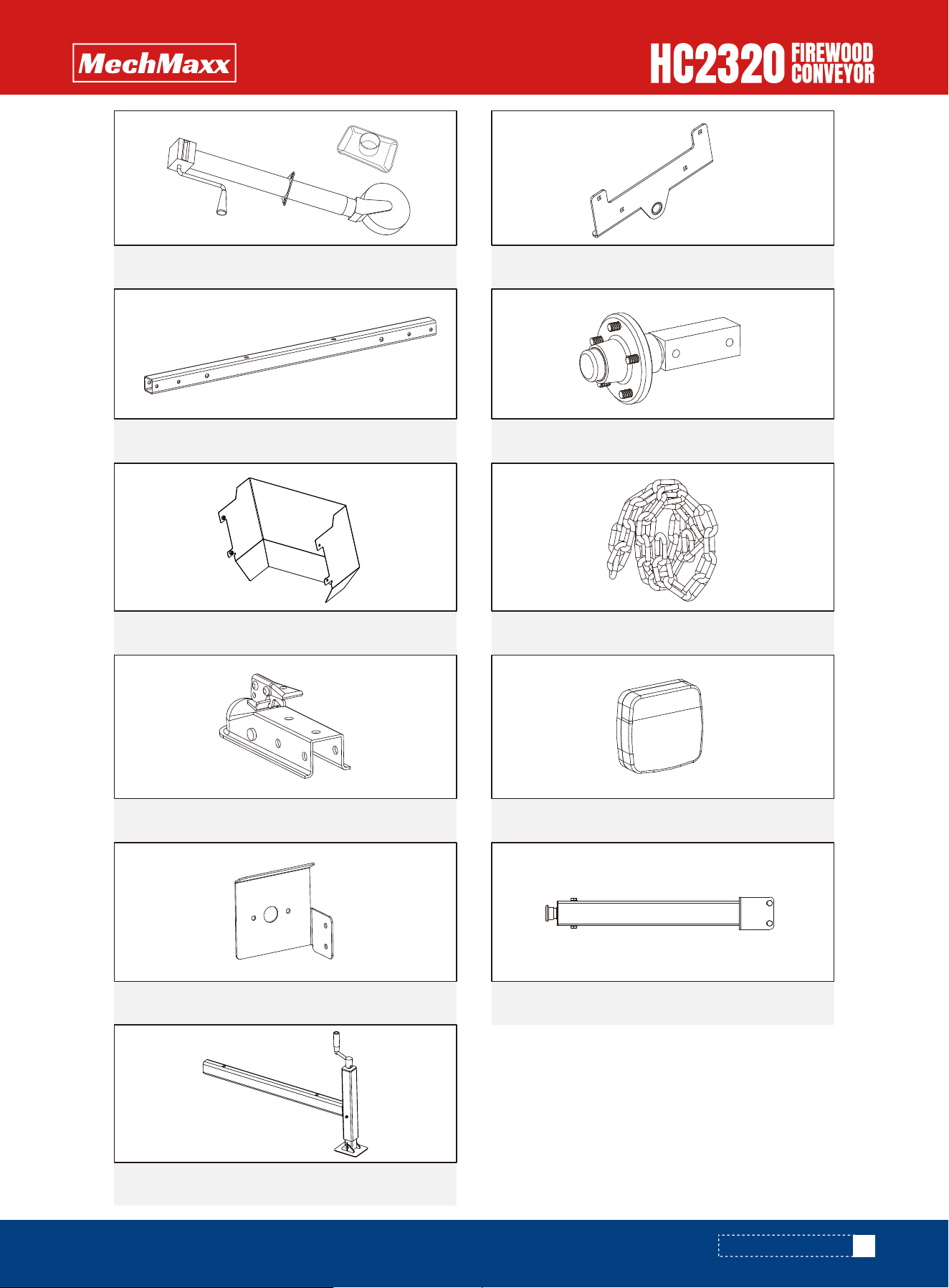
Verify all component and hardware
quantities are correct prior to
assembling the Firewood Conveyors.
TRAILER JACK
1x
SUPPORT BASE
2x
AXLE SQUARE TUBE
2x
AXLES
2x
MATERIAL STOP PLATE
2x
SAFETY CHAIN
1x
HITCH BALL COUPLER
1x
TAILLIGHT
2x
EMERGENCY STOP BUTTON
1x
TAIL LIGHT BRACKET
2x
2x REAR SUPPORT STAND
9
www.mechmaxx.com
CONTENTS SUPPLIED
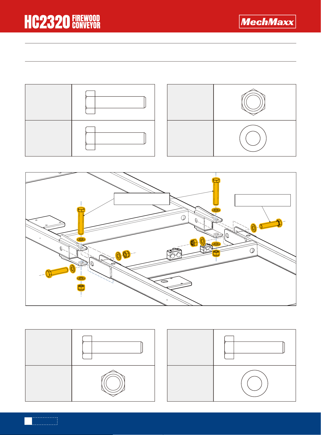
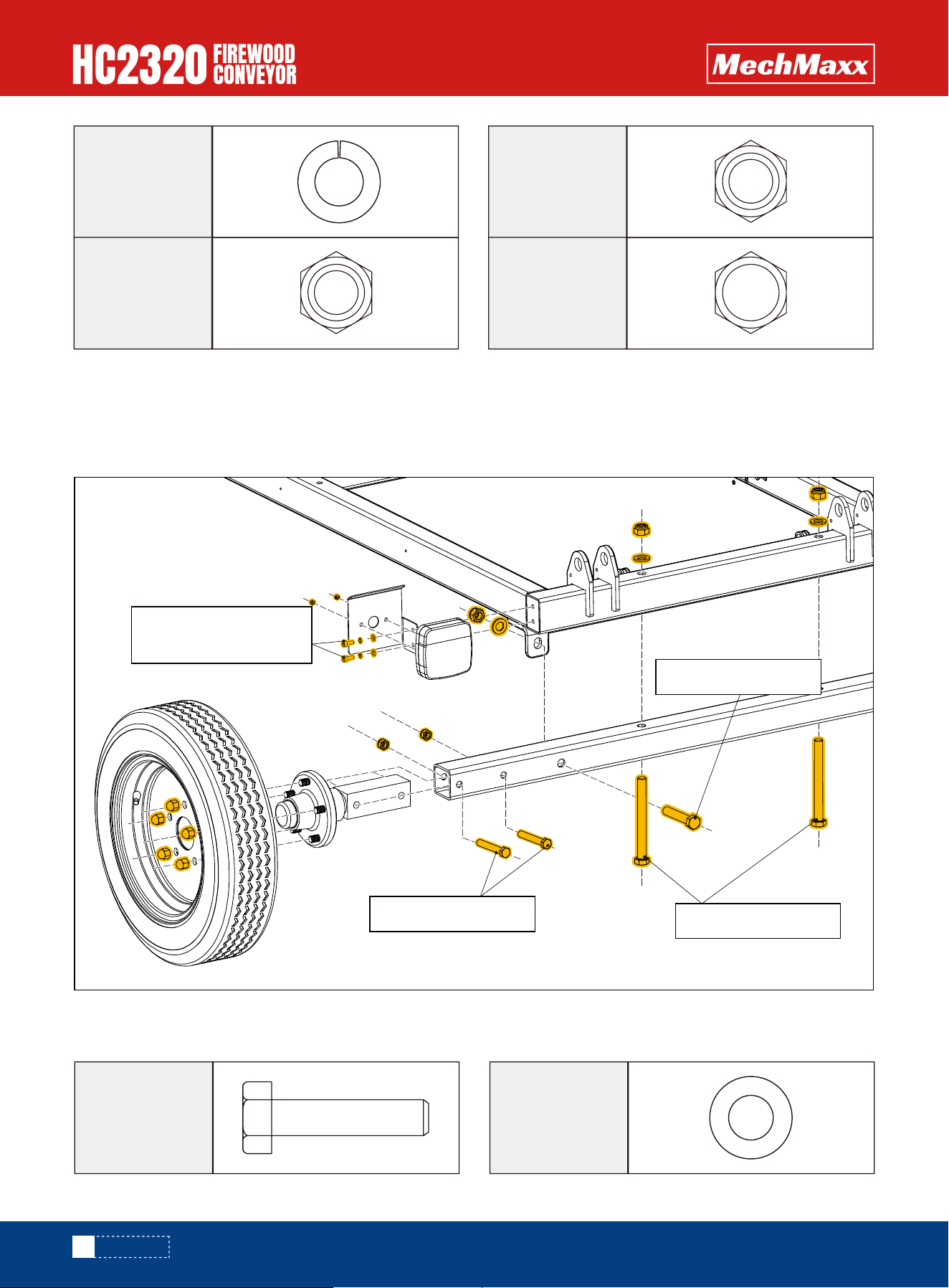
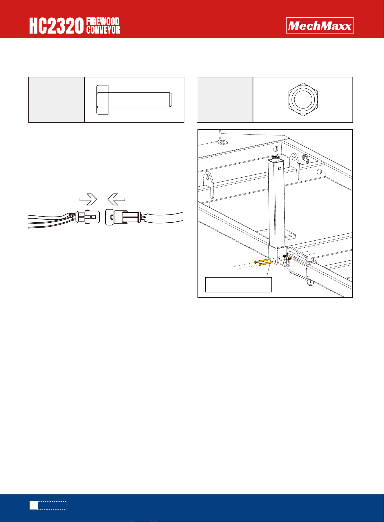
Use Hex bolt M20×120, Hex bolt M20x100, Hex lock nut M20 and Flat washer, to assemble the chassis together.
Before assembling the chassis, please prepare the following parts.
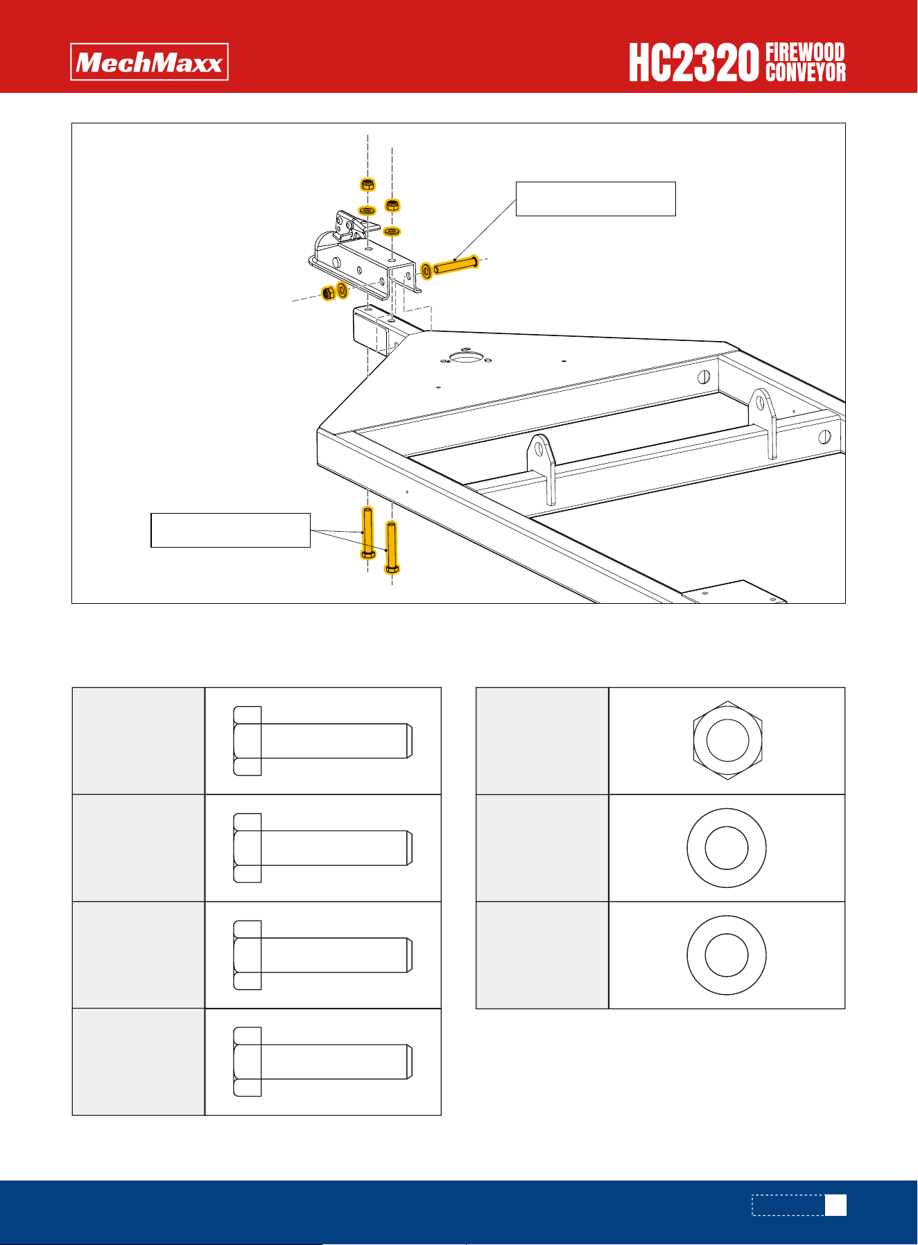
Before assembling the coupler, please prepare the following parts.
CHASSIS ASSEMBLY
HITCH COUPLER ASSEMBLY
ASSEMBLY
2X
Hex bolt
M20x120
1X
Hex bolt
M10x80
2X
Hex bolt
M12x80
2X
Hex bolt
M20x100
8X
4X
Hex lock
nut M20
3X
Hex lock
nut M12
Flat washer
20
4X
Flat washer
12
Hex bolt M20x120
Hex bolt M20x100
10
www.mechmaxx.com
ASSEMBLY
4X
Hex bolt
M16x160
4X
Hex bolt
M12x85
2X
Hex bolt
M16x85
4X
Hexagon
socket bolts
M6x16
6X
10X
Wheel nut
M12
Flat washer
16
4X
Flat washer
6
Before assembling, please prepare the following parts.
ASSEMBLE TIRES, AXLES AND TAILLIGHTS
Hex bolt M10x80
Hex bolt M12x80
11
www.mechmaxx.com
ASSEMBLY
3X
Hex bolt
M8x30
6X
Flat washer
8
4X
Before assembling, please prepare the following parts.
Install the axle to the chassis using Hex bolt M16x160, Hex lock nut M16 and Flat washer, and secure it with Hex bolt
M16x85, Hex lock nut M16 and Flat washer.
Install the tire to the axle using Hex bolt M12x85 and Hex lock nut M12.
Mount the taillight to the chassis using Hexagon socket bolts M6x16, Spring washer 6 and Flat washer 6.
TRAILER JACK ASSEMBLY
Spring
washer 6
6X
Hex lock
nut M16
4X
Hex lock
nut M12
4X
Hexagonal
lock nut M5
Hex bolt M16x160
Hex bolt M12x85
Hex bolt M16x85
Hexagon socket bolts
M6x16
12
www.mechmaxx.com
ASSEMBLY
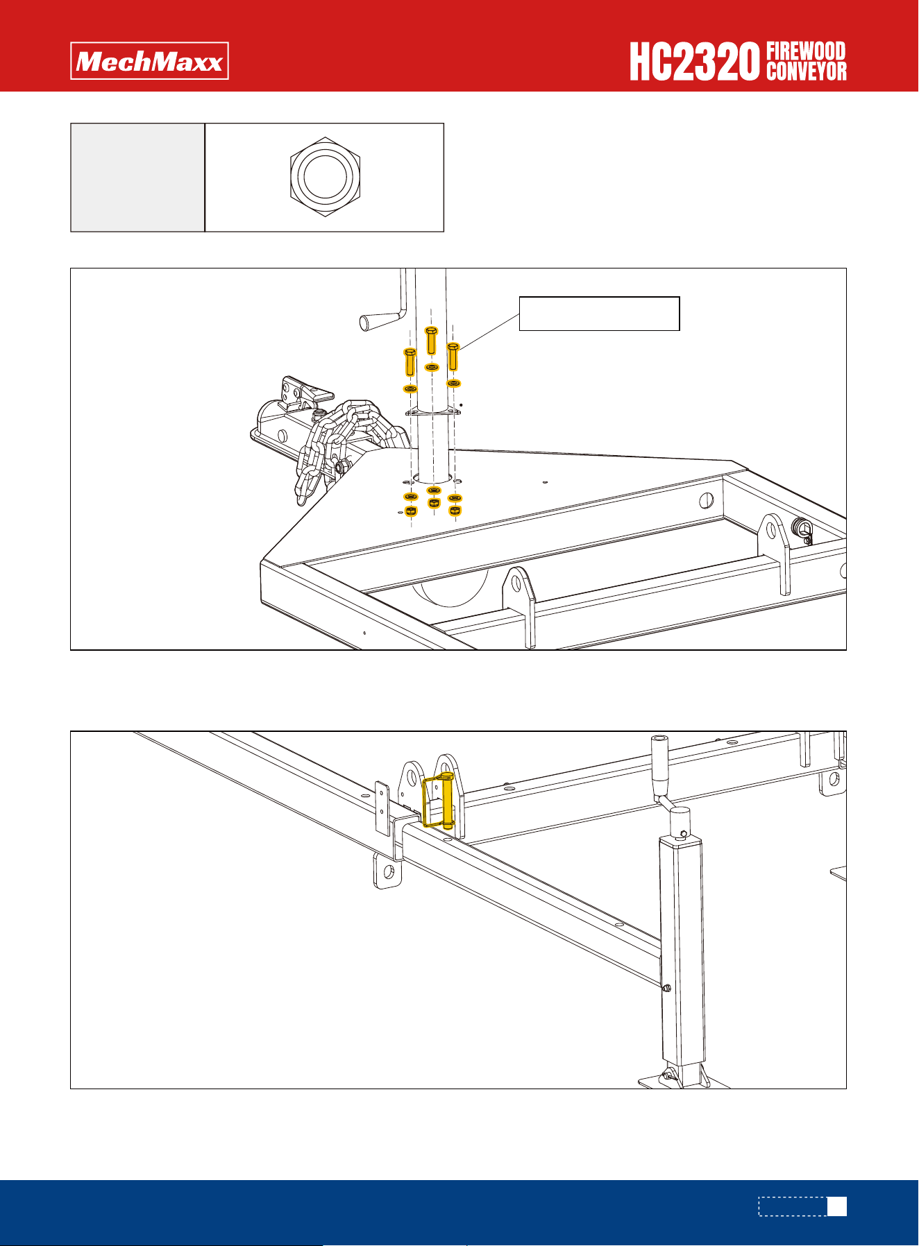
Assemble the trailer jack to the chassis using Hex bolt M8x30, Hex lock not M8, and Flat washer 8.
Secure the Rear Support Stand to the Chassis using a 12×80 square lock pin.
REAR SUPPORT STAND
3X
Hex lock
nut M8
Hex bolt M8x30
13
ASSEMBLY
www.mechmaxx.com
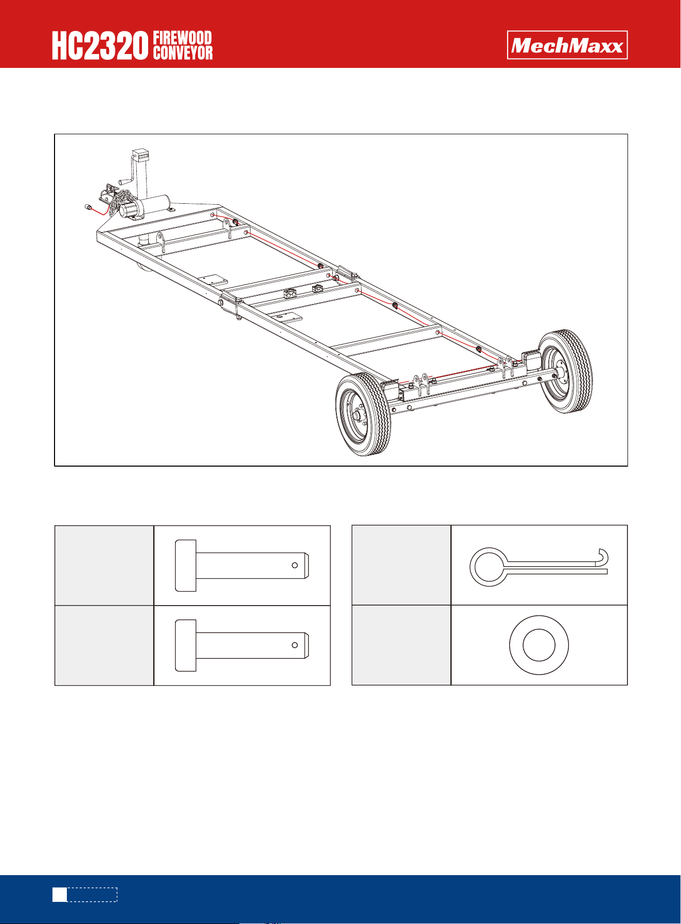
Refer to the figure below to install the wiring harness to the chassis.
TAIL LIGHT CABLE ASSEMBLY
BRACKET ASSEMBLY
CLOSED
Before assembling, please prepare the following parts.
Using pin 2, flat washer C, and cotter pin 5×50, assemble the bracket to the chassis.
4X
Pin 1
4X
Cotter Pin
5x50
6X
Flat washer
C
4X
Pin 2
14
ASSEMBLY
www.mechmaxx.com
CONVEYOR BELT
OPEN
Before assembling, please prepare the following parts.
8X
Square neck
bolt M10x25
4X
Square neck
bolt M10x35
12X
Flat washer
10
8X
Hex lock
nut M10
4X
Hex lock
nut M12
15
ASSEMBLY
Pin 1
Pin 2
www.mechmaxx.com
CONVEYOR BELT ASSEMBLY
Before assembling, please prepare the following parts.
54X
Flat washer
10
6X
Flat washer
8
48X
Square neck
bolt M10x25
6X
Hex bolt
M8x20
4X
Hex bolt
M10x25
6X
Hex bolt
M10x20
48X
Hex lock
nut M10
6X
Spring
washer 8
6X
Spring
washer 10
16
ASSEMBLY
Square neck
bolt M10x25
Square neck
bolt M10x35
www.mechmaxx.com
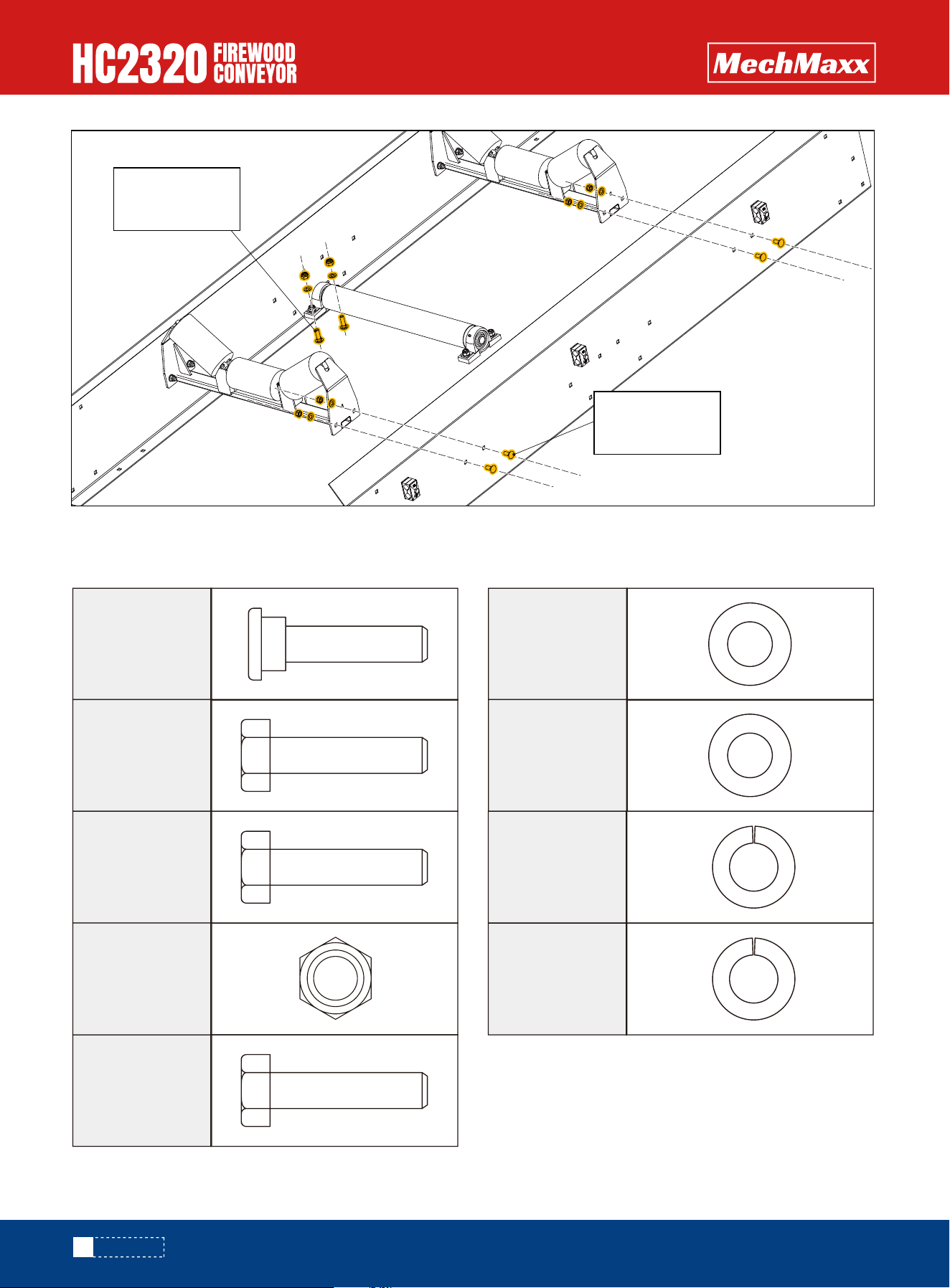
Use Square neck bolt M10x25, Hex lock nut M10 and Flat washer 10 to assemble section A and section B together.
Use Square neck bolt M10x25, Hex lock nut M10 and Flat washer 10 to assemble section B and section C together.
A
B
B
C
A B C D
Square neck
bolt M10x25
Square neck
bolt M10x25
17
ASSEMBLY
www.mechmaxx.com
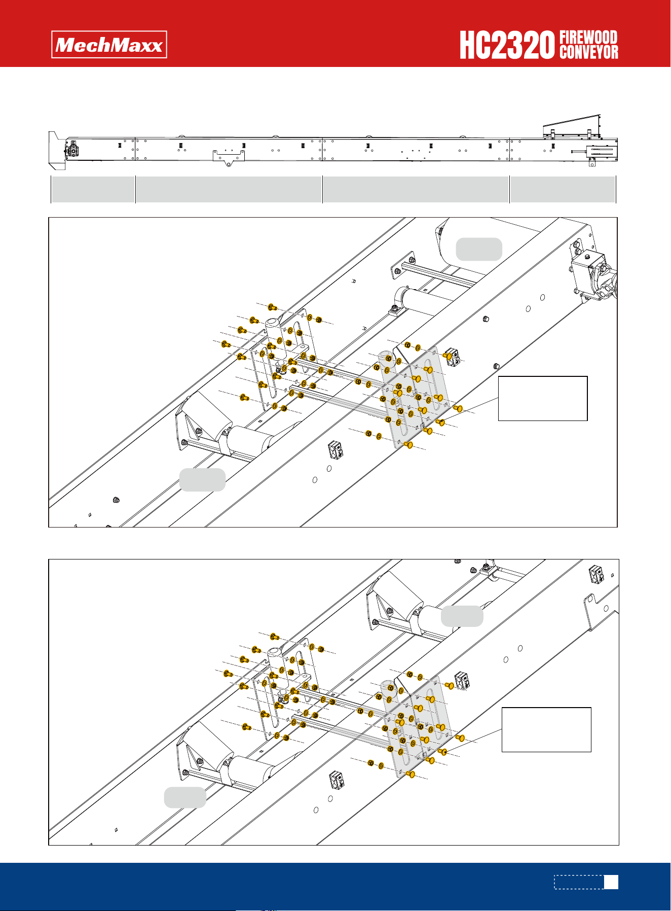
Use Square neck bolt M10x25, Hex lock nut M10 and Flat washer 10 to assemble section C and section D together.
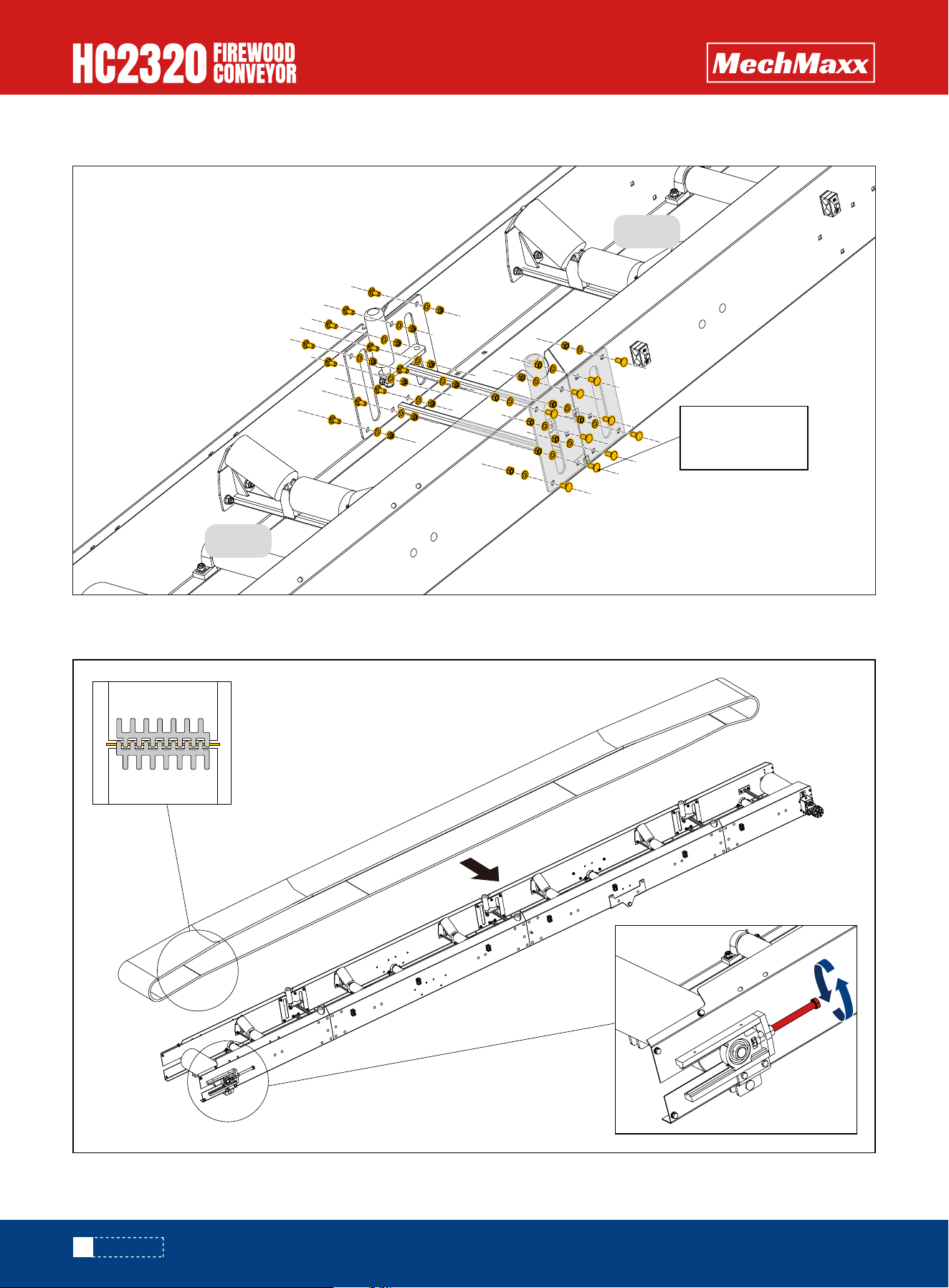
Once the four conveyor belt sections are assembled, assemble the belt to the conveyor belt.
Once installation is complete, secure the conveyor belt with the connecting clip.
Make adjustments to the belt take-up adjuster bolt to center the belt on the pulley.
C
D
Square neck
bolt M10x25
18
ASSEMBLY
www.mechmaxx.com
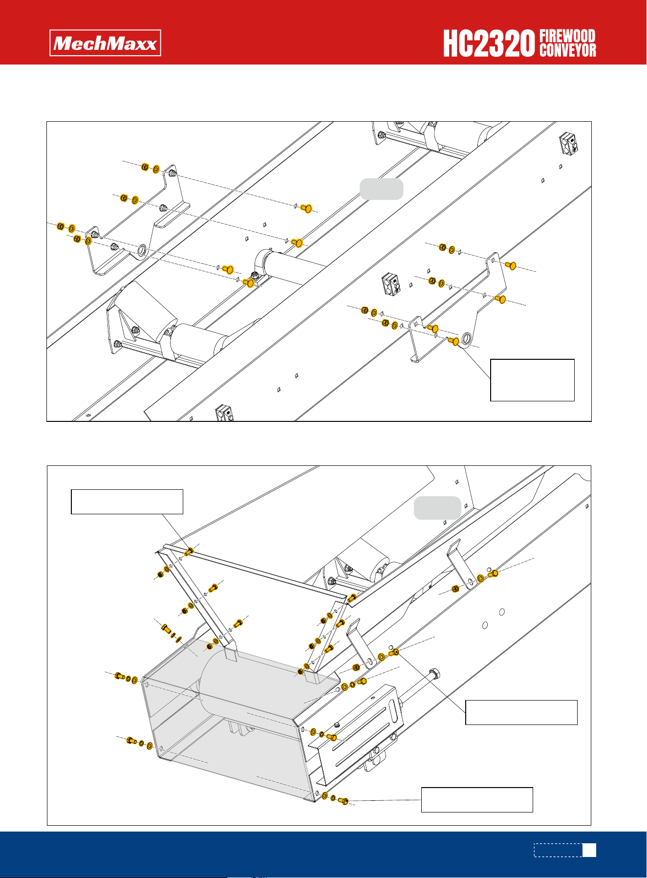
Assemble the support base plate and segment B together using square neck bolts M10 × 25, hexagon socket lock nuts
M10 and plain washers 10.
Assemble the hopper and bottom guard to the D section using Hex bolt M10x25, Hex bolt M8x20, Hex bolt M10x20, Flat
washer 10 and Spring washer 10.
19
ASSEMBLY
Square neck
bolt M10x25
B
Hex bolt M10x25
Hex bolt M10x20
Hex bolt M8x20
D
www.mechmaxx.com
Hex bolt M8x70
Before assembling, please prepare the following parts.
Use Hex Bolt M8×70 to assemble the Emergency Stop
Button onto the Chassis.
*Connect the emergency stop wire to the other end of the
engine by inserting the wire into the engine connector.
4X
Hex bolt
M8x70
4X
Hex lock
nut M8
EMERGENCY STOP BUTTON
20
ASSEMBLY
www.mechmaxx.com
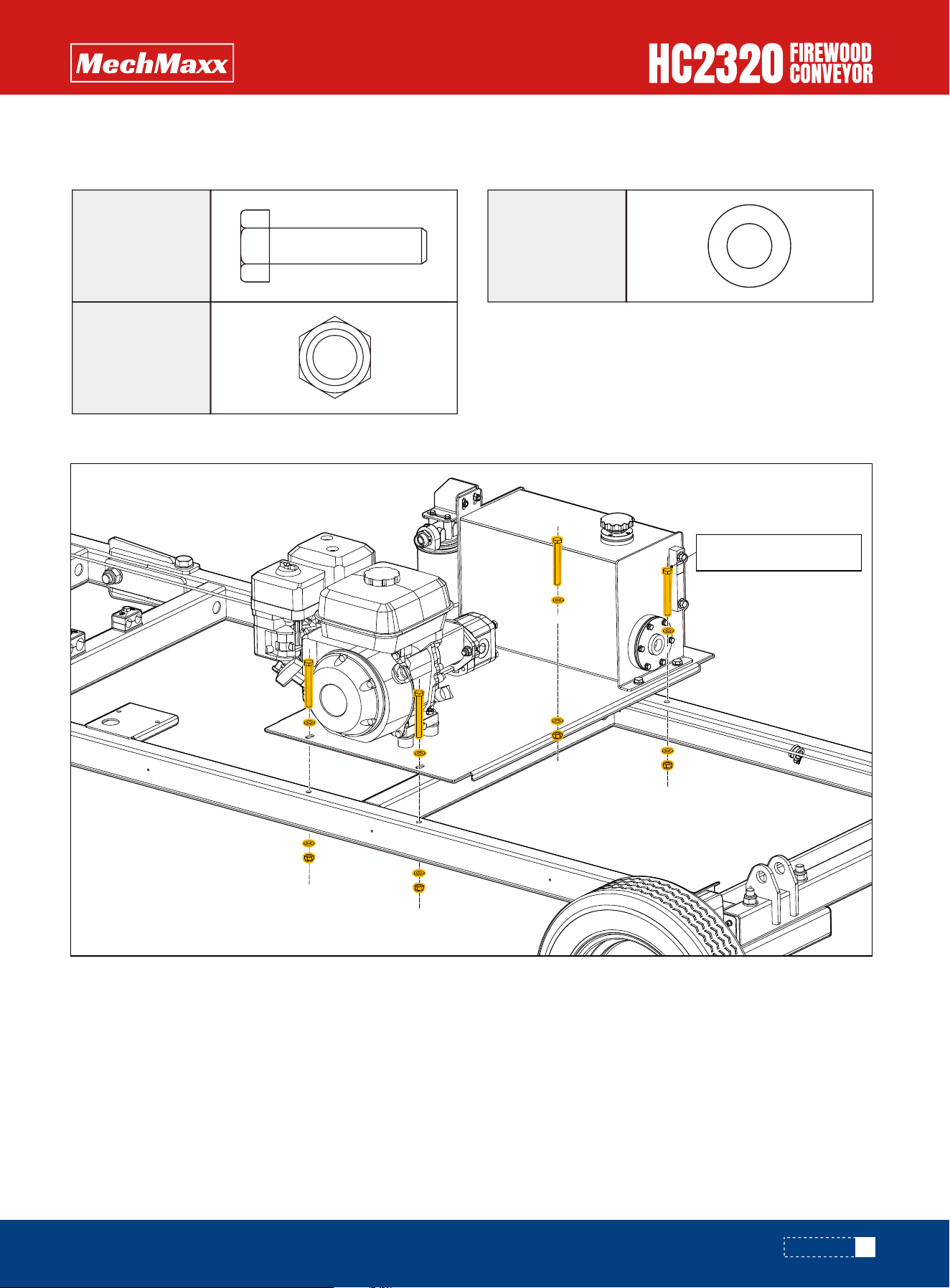
Hex bolt M10x90
ENGINE AND HYDRAULIC TANK ASSEMBLY
Before assembling, please prepare the following parts.
Assemble the engine and hydraulic tank to the chassis using Hex bolt M10x90, Flat washer 10 and Hex lock nut M10.
8X
Flat washer
10
4X
Hex bolt
M10x90
4X
Hex lock
nut M10
21
ASSEMBLY
www.mechmaxx.com
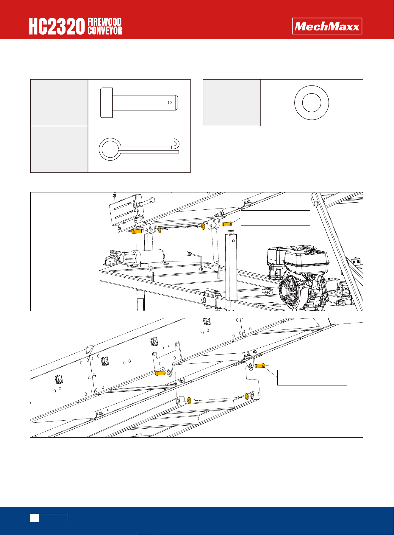
Connecting Shaft 1
Connecting Shaft 1
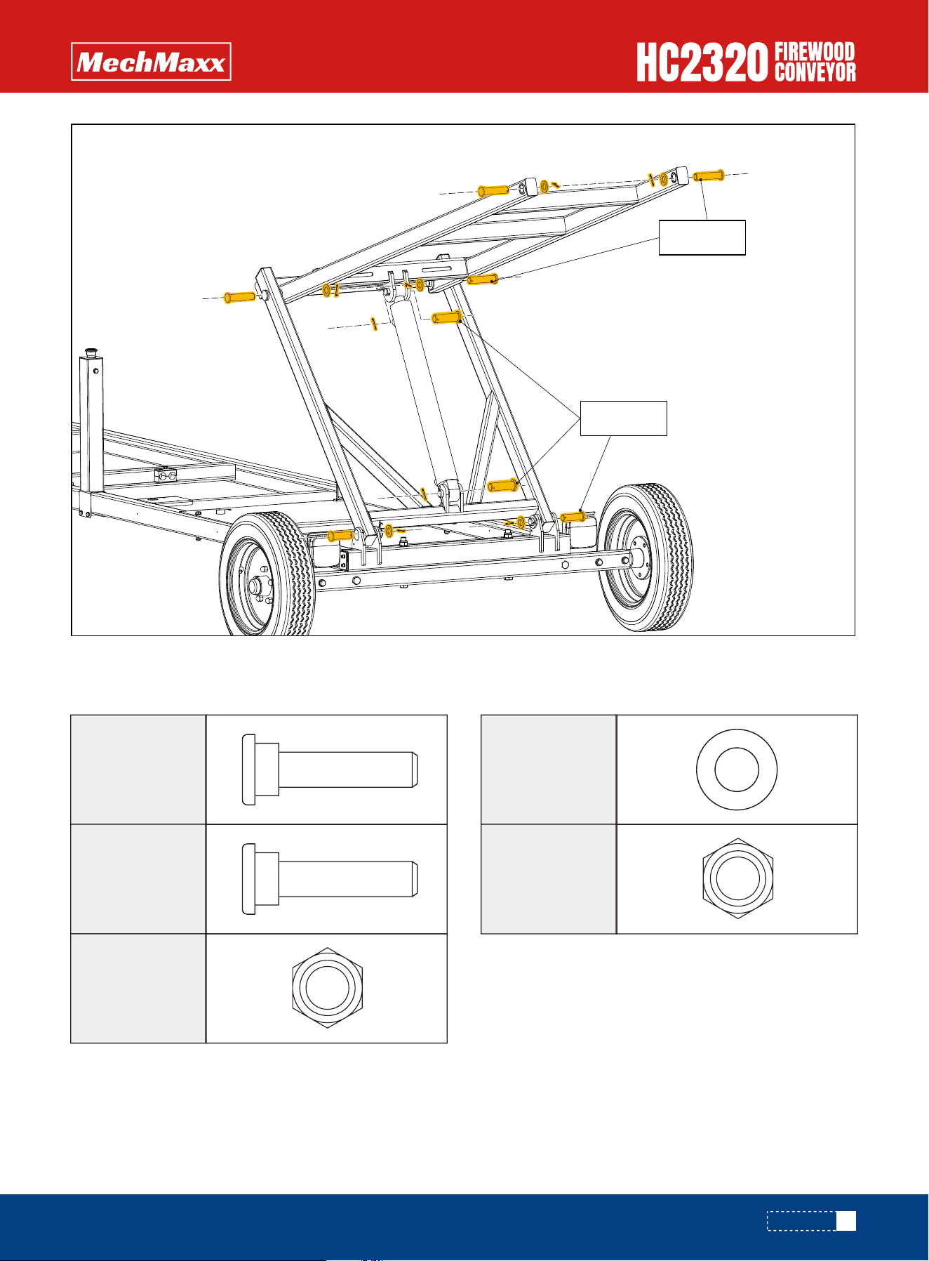
CONVEYOR BELT AND CHASSIS ASSEMBLY
Before assembling, please prepare the following parts.
Assemble the conveyor belt to the lifting bracket using Connecting Shaft 1, Flat washer C 24 and Cotter Pin 5x50.
4X
Connecting
Shaft 1
4X
Cotter Pin
5x50
4X
Flat washer
C 24
22
ASSEMBLY
www.mechmaxx.com
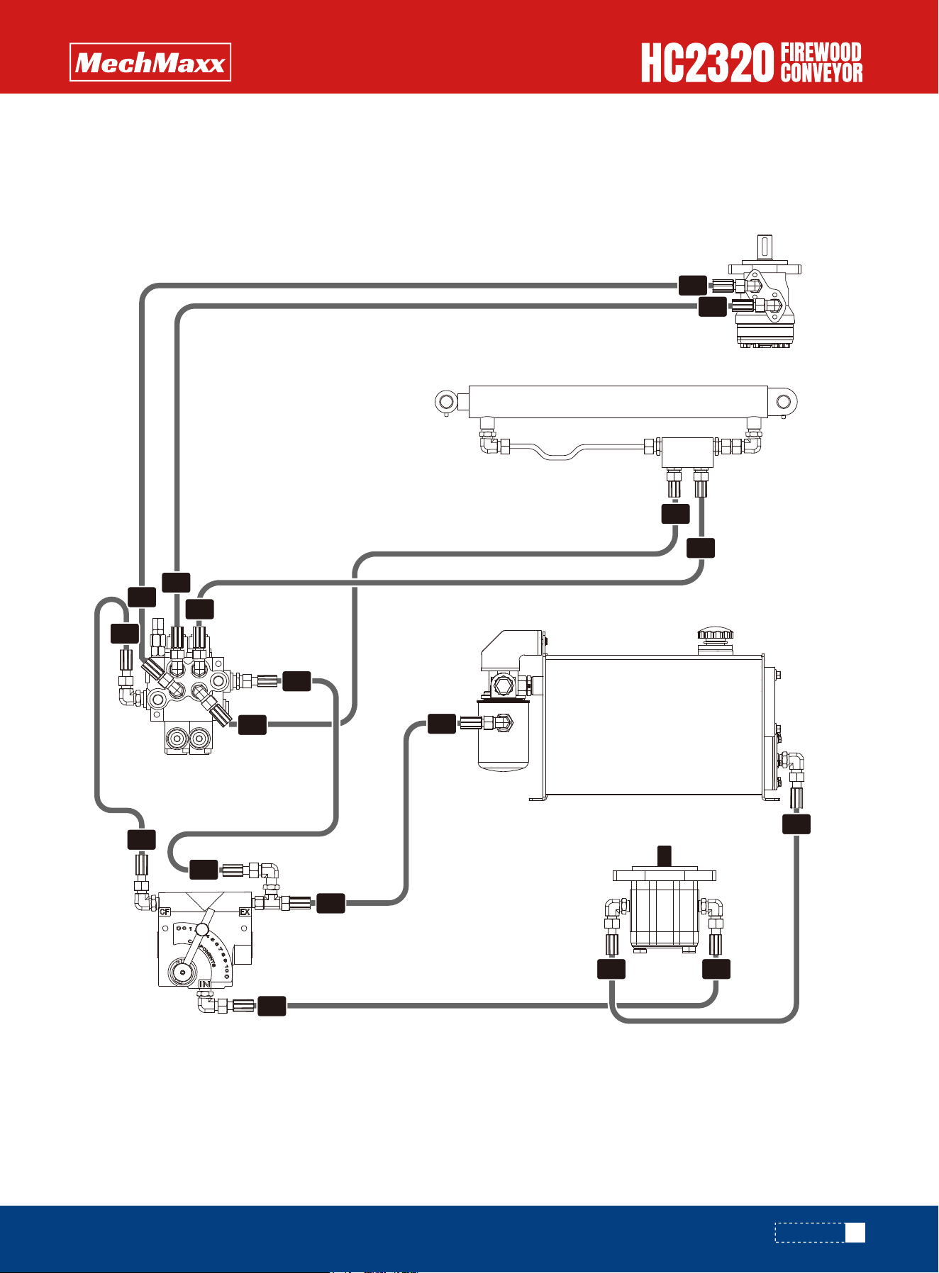
HYDRAULIC SYSTEM ASSEMBLY
Assemble the hydraulic system as shown in the figure.
Hydraulic system connection diagram.
23
ASSEMBLY
Motor
Cylinder
Gear
Pumps
Two-Way Valve
Speed Adjustment Valve
Oil Tank
Return
Filter
A1
C1
D1
J1
G2J2
G1
H1
H2
E1
F1
E2
C2
D2
B2
F2
A2
B1
www.mechmaxx.com
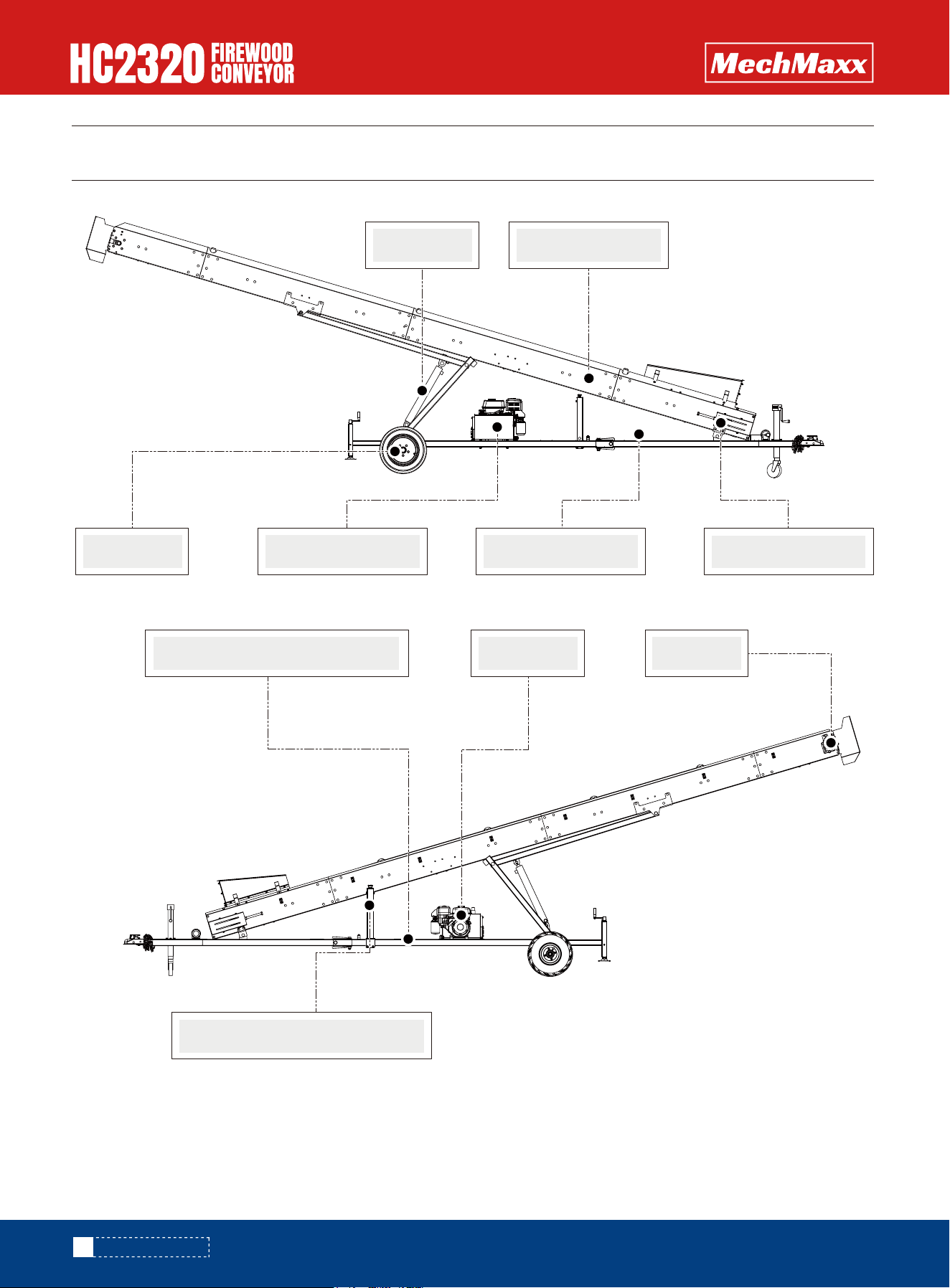
KNOW YOUR MACHINE
24
KNOW YOUR MACHINE
Cylinder Conveyor Belt
Wheels Hydraulic tank
Belt Take-up
Two-Way Valve
Engine
Emergency Stop Button
Motor
Speed Adjustment Valve
www.mechmaxx.com
OPERATION
Do not operate the equipment until you have set up an
operating safety zone around the conveyor.
Do not operate the conveyor if it is missing any guard, or
other safety device.
Do not reach through any piece of equipment for any
reason, whether it is in operation or not.
Do not let unauthorized and untrained individuals on or
around the equipment. Never allow anyone to stand under
the conveyor, whether it is in operation or not. Maintain
the safety zone. Be especially watchful while raising or
lowering the bin and or conveyor.
Do not let unauthorized and untrained individuals, espe-
cially small children, on, around or near the equipment.
Do not attempt to use the conveyor equipment unless you
have been fully trained in its operation.
Operate the conveyor only when your view of the conveyor
and the surrounding are clear and unobstructed.
When starting the conveyor, notify all people in the imme-
diate vicinity.
Make sure conveyor is on a stable ground surface and
placed as close to level as possible.
Make sure all guards are in place before operating the
conveyor
Inspect conveyor for any hazards or interfering objects
that may come in contact with the conveyor when start-
ing the conveyor. Make sure all maintenance has been
done.
Be careful not to overload the conveyor belt with the
material you are trying to move.
1. Make sure the Firewood conveyors is on a flat, level
surface.
2. Remove the oil fill cap/dipstick to add oil.
Read and understand all the safety
information in this manual before you
operate the machine.
The operator is responsible to be
familiar with and obey all operating
and safety procedures.
OPERATING SAFETY
ADD OIL TO ENGINE
The engine is shipped without oil. Do
not start the engine before adding oil.
Because of the many moving parts on
the conveyor, all personnel in the area
of the conveyor need to be warned that
the conveyor is about to be started.
3. Using a funnel, add oil up to the FULL mark on the
dipstick. (See engine manual for oil capacity, oil recom-
mendation, and location of fill cap.).
CLOSEDOPEN
DO NOT OVERFILL. Check engine oil
level daily and add as needed.
25
OPERATION
www.mechmaxx.com
The engine must be off and allowed to cool at least two
minutes before adding fuel.
Remove the fuel filler cap and fill the tank. (See engine
manual for fuel capacity, fuel recommendation, and
location of fuel cap.)
This equipment and/or its engine may
include evaporative emissions control
system components, required to meet
EPA and/or CARB regulations, that will
only function properly when the fuel
tank has been filled to the recommend-
ed level. Overfilling may cause perma-
nent damage to evaporative emissions
control system components. Filling to
the recommended level ensures a vapor
gap required to allow for fuel expan-
sion. Pay close attention while filling
the fuel tank to ensure that the recom-
mended fuel level inside the tank is not
exceeded. Use a portable gasoline
container with an appropriately
sized dispensing spout when filling the
tank. Do not use a funnel or other
device that obstructs the view of the
tank filling process.
Gasoline is highly flammable and
explosive. You can be burned or
seriously injured when handling fuel.
Use extreme care when handling gaso-
line.
Fill the fuel tank outdoors, never
indoors. Gasoline vapors can ignite if
they collect inside an enclosure. Explo-
sion can result.
ADD GASOLINE TO ENGINE
IMPORTANT:DO NOT OVERFILL!
3. Reinstall the fuel cap and tighten. Always clean up
spilled fuel.
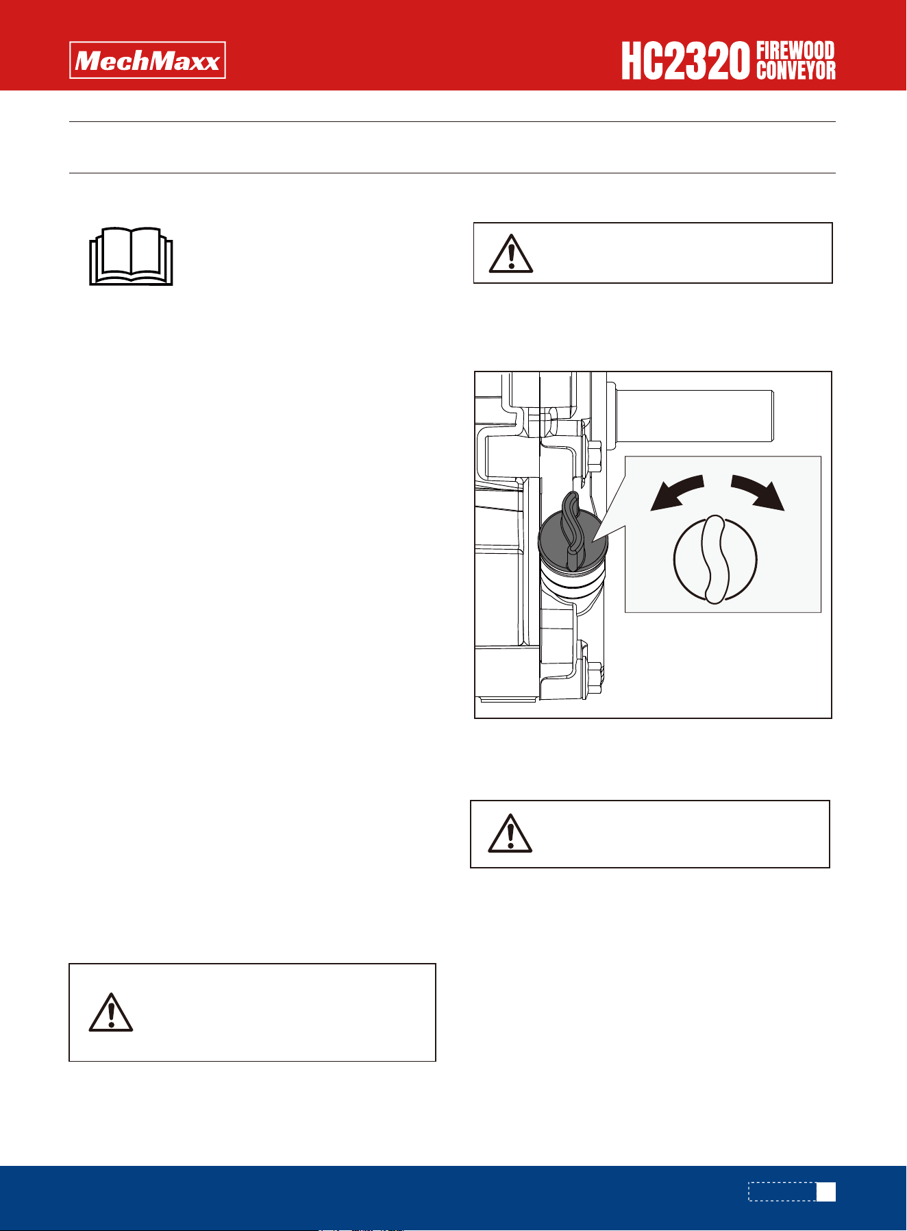
2.Open the fuel shut-off valve.
1. Move the engine switch to the ON position.
STARTING ENGINE
ONOFF
ONOFF
3.Move the choke lever to the CLOSED position.
If the engine is hot, closing the choke is not necessary.
OPENCLOSED
26
OPERATION
www.mechmaxx.com
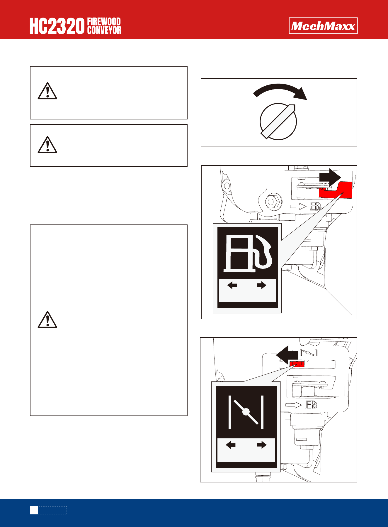
OPERATING
4. Move the throttle lever slightly to the FAST speed.
SLOWFAST
5. Pull the recoil starter until engine compression has
become difficult to pull. Let the recoil return to the home
position, then pull quickly to start the engine. Repeat
steps as needed. Fully open the choke and set the throt-
tle to the FAST position, before operating the unit.
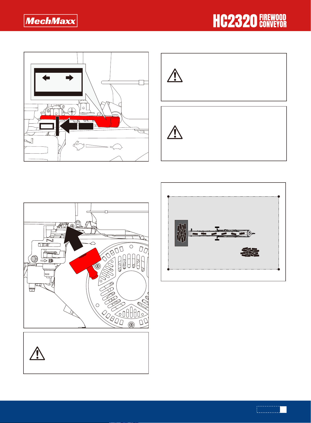
1. Choose a flat location and establish a safe working
area.
2. Move the conveyor belt so that the machine points in
the direction you want the firewood to be stacked.
3. Block the machine wheels to prevent movement.
4. Adjust the transport angle.
5. Start the machine. For instructions, see Starting
Engine on page 14.
6. Place the firewood on the conveyor belt, do not put too
much firewood on the conveyor at one time.
Rapid retraction of the starter cord
(kickback) will pull your handand arm
toward the engine faster than you can
let go. Broken bones, fractures, bruis-
es, or sprains could result.
Never start or run the machine inside a
closed area. The exhaust fumes are
dangerous. containing carbon monox-
ide, an odorless and deadly gas. Oper-
ate this unit only in a well ventilated
outdoor area.
Do not adjust the conveyor angle, move
or turn the machine while the machine
is running or there is firewood on the
conveyor belt. Before adjusting the
conveyor angle, moving or turning the
machine, stop the machine and remove
all firewood.
27
OPERATION
www.mechmaxx.com
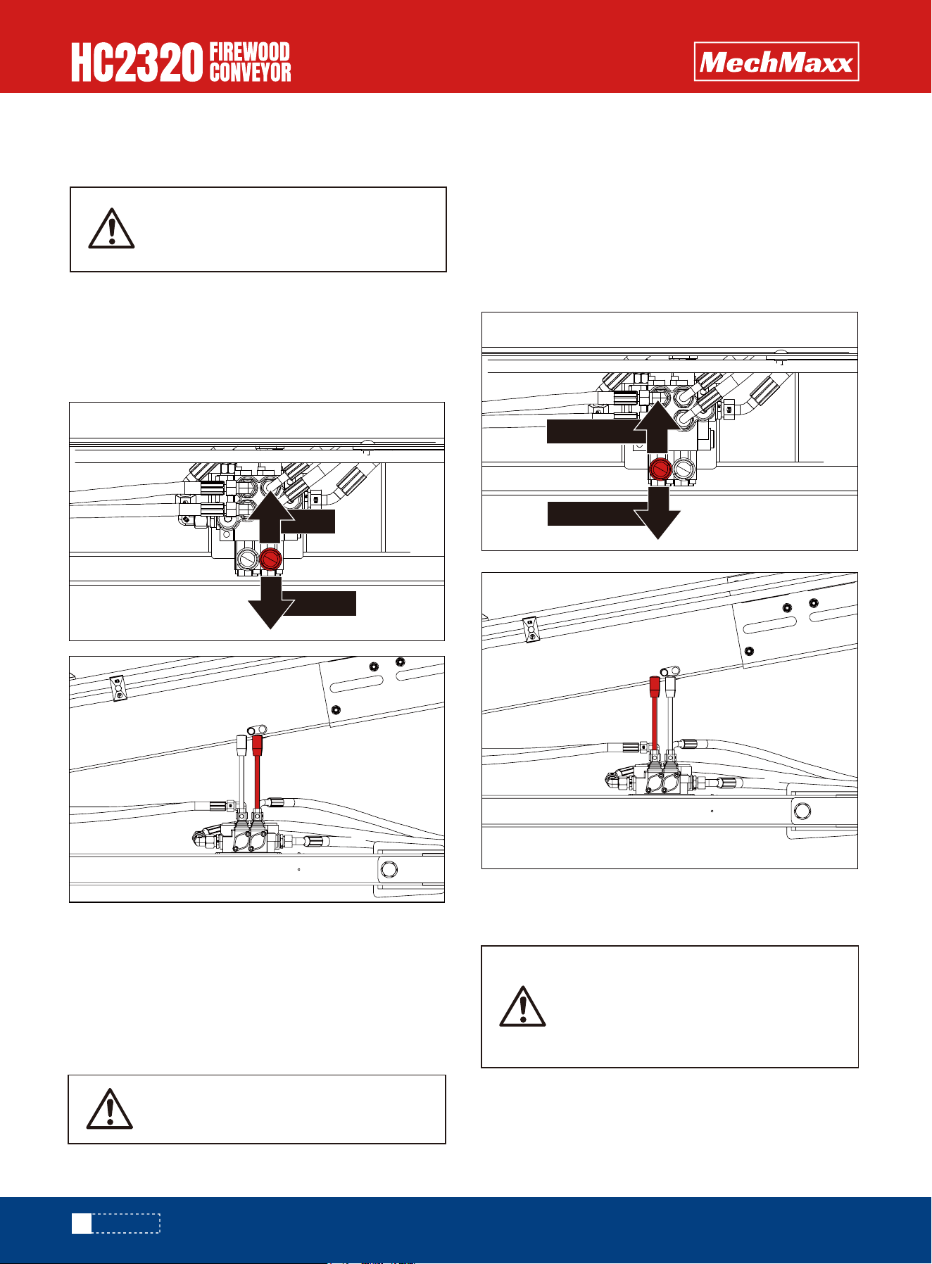
HYDRAULIC ADJUSTMENT OF
CONVEYOR ANGLE
HYDRAULIC CONTROL OF THE
DIRECTION OF TRANSMISSION
HYDRAULICALLY CONTROLLED
CONVEYOR SPEED
As shown in the figure, the conveyor angle is adjusted by
the handle.
Push the adjustment rod forward to increase the conveyor
belt angle, and push the adjustment rod backward to
decrease the conveyor belt angle.
*At the lowest position (94.4 in), the maximum load
capacity of the conveyor belt must not exceed 440 lbs.
At the highest position (177.1 in), the maximum load
capacity of the conveyor belt must not exceed 352 lbs.
The load must be evenly distributed across the convey-
or belt. Do not place items exceeding the maximum
load limit at a single point.
As depicted in the figure, the direction of the conveyor
belt is regulated by the handle.
When you push the adjustment lever forward, the convey-
or belt moves in an upward - transport direction.
Conversely, when you push the adjustment lever back-
ward, the conveyor belt transports downward.
Conveyor speed indication, “0” is slowest and “10” is
fastest.
Do not adjust the conveyor angle when
the machine is on or there is firewood
on the conveyor.
Do not adjust the conveyor speed when
there is firewood on the conveyor belt.
Stop the machine and remove all
firewood before adjusting the conveyor
speed.
Warning: Do not overload. Overloading
may cause tipping.
Lift
Lower
Forward
Reverse
28
OPERATION
www.mechmaxx.com
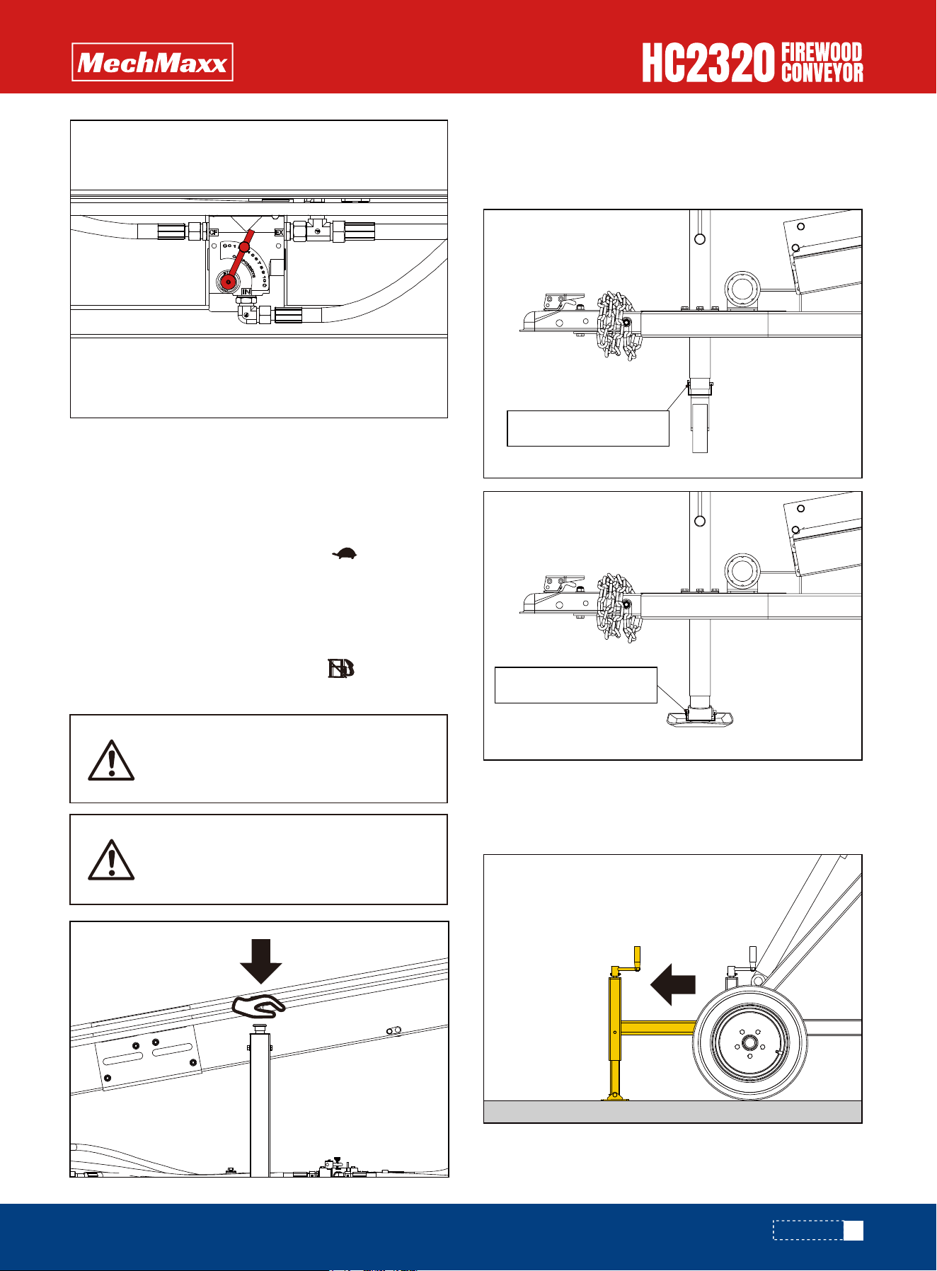
To stop the engine in an emergency, simply turn the
engine switch to the OFF position. Under normal condi-
tions, use the following procedure:
Remove the jack wheel and assemble the base plate to
the jack using a 10x70 square pin.
Pull out the rear support frame before use to provide
additional support.
Sudden stopping at a high speed under
a heavy load is not recommended.
Engine damage may result.
Do not move the choke control to
CLOSE to stop the engine. Backfire or
engine damage may occur.
SUPPORT JACK
STOP ENGINE
1. Move the throttle lever to the SLOW ( )
position.
2.Let the engine idle for one or two minutes.
3.Turn the engine switch to the OFF position.
4. Turn the fuel valve lever to the OFF ( )
position.
10x70 square pin
29
OPERATION
10x70 square pin
REAR SUPPORT STAND
www.mechmaxx.com
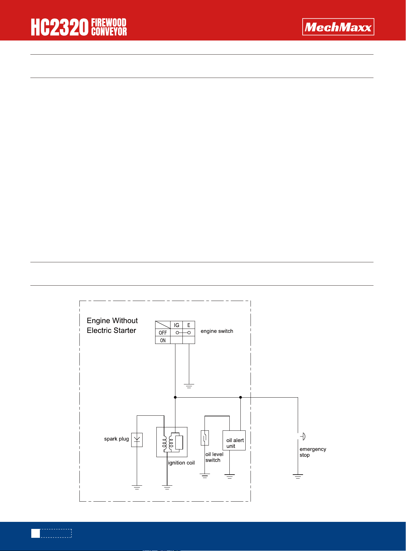
TRANSPORT
WIRING DIAGRAM
Make sure conveyor is empty no debris or material that
may fall off.
Use safety chains while traveling.
Use safety flags to properly mark conveyor while traveling
on road.
Support legs should be raised completely and secured
with the locking bolts.
Raise the hitch by turning jack to a height higher than the
ball on the receiver (always use a 2"ball).
With latch in raised position on the hitch of the conveyor,
center ball directly underneath. Once in position lower the
conveyor onto ball completely. Latch hitch being sure it is
latched completely. Attach safety chains to receiver.
Pull pin from jack and put in horizontal position and
reattach pin.
Requires a 2 inch ball for towing.
Be sure conveyor is set at towing position with jack
pressure screw released.
Do not allow people to ride on the machine.
Do not exceed a safe speed.
Reduce speed on rough terrain and when turning.
Plan your route to avoid heavy traffic.
Do not transport or move the machine with the engine
running.
Make sure the fuel cap is on and tight.
Make sure all guards and shields are installed and guards
are closed.
Clear all debris from the machine.
Check tires for cuts or damage.
TOWING
TRANSPORT SAFETY
30
TRANSPORT
www.mechmaxx.com
MAINTENANCE
If any part of the protective structure is affected by a
plastic deformation and/or rupture, the protective struc-
ture must be replaced according to manufacturer's speci-
fications.
1. Turn off the engine and release all control levers. The
engine must be cool.
2. Keep the engine's throttle lever in the slow position,
remove the spark plug wire from the spark plug and secure
it.
3. Check for loose screws, misalignment or sticking of
moving parts, cracked or broken parts, and any other
conditions that may affect its safe operation.
4. Use a soft brush, vacuum cleaner or compressed air to
remove all contaminants from the machine. Then lubricate
all moving parts with high-quality light oil.
5. Check the spark plug wire regularly for signs of wear
and replace it if necessary.
Change hydraulic oil and filter after every 200 hours of
operation, or once a season.
AW-46 grade is recommended and should be changed two
inches below the top of the reservoir.
Note: If the hydraulic oil becomes contaminated, it should
be changed immediately to prevent damage to the
system.
Unless you are trained to repair hydraulic systems, you
must have a qualified person repair the system.
First change after first 5 hours of operation.
Regular changes after every 20 hours of operation.
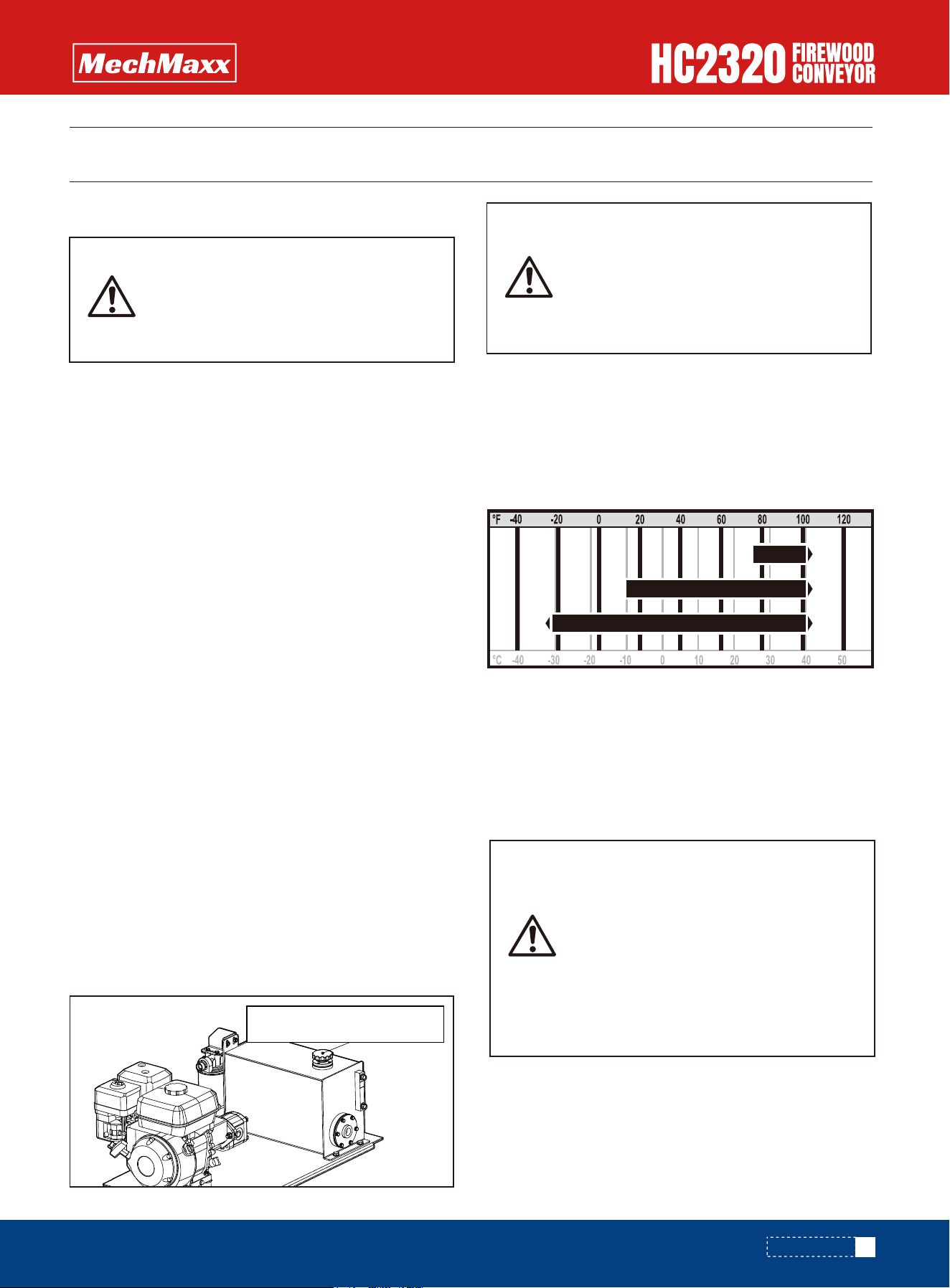
The outdoor temperature determines the necessary
engine oil viscosity. Use the following chart as a guide:
Unleaded gasoline
Pump octane rating 86 or higher.
This engine is certified to operate on unleaded gasoline.
Unleaded gasoline produces fewer engine and spark plug
deposits and extends exhaust system life.
MAINTENANCE PRECAUTIONS
HYDRAULIC OIL
ENGINE OIL
RECOMMENDED FUEL
Make sure engine is shut off and
hydraulic system is depressurized
before you perform any maintenance.
Make sure hydraulic oil has cooled.
Gasoline is highly flammable and
explosive, and you can be burned or
seriously injured when refueling.
• Stop engine and keep heat, sparks,
and flame away.
• Refuel only outdoors.
• Wipe up spills immediately.
After the hydraulic oil tank is filled to
the marked level, the equipment needs
to be started to allow the hydraulic oil
to fill the pipeline, and then the hydrau-
lic oil is refilled to the marked level.
SAE 30
SAE 15W-40
SAE 10W-30
31
MAINTENANCE
Hydraulic oil filling port
www.mechmaxx.com
COMPONENT SUGGESTED ACTION MONTHLY QUARTERLY
MOTOR
WEEKLY
Check Noise
Check Temperature
Check Mounting Bolts
REDUCER
Check Noise
Check Temperature
Check Oil Level
BELT
Check Tracking
Check Tension
Check Lacing
HYDRAULICS
Check for any leaks
Check Oil Level in Reservoir
Check for Loose fittings - tighten
BEARINGS
STRUCTURAL
Check Noise
Check Lubrication
Check Mounting Bolts
General Check: All loose bolts, etc.
tightened
Make adjustments to the belt take-up adjuster bolt to center the belt on the pulley. Example: If the belt is steering off
the pulley to the left side, the take-up bolt on the left side can be adjusted outward to push the belt back to the right. Or,
the right take-up bolt can be loosened to bring the belt back to the right.
HOW TO STEER THE BELT
MAINTENANCE INTERVAL CHART
32
MAINTENANCE
Tail Pulley
Belt Take-up
www.mechmaxx.com
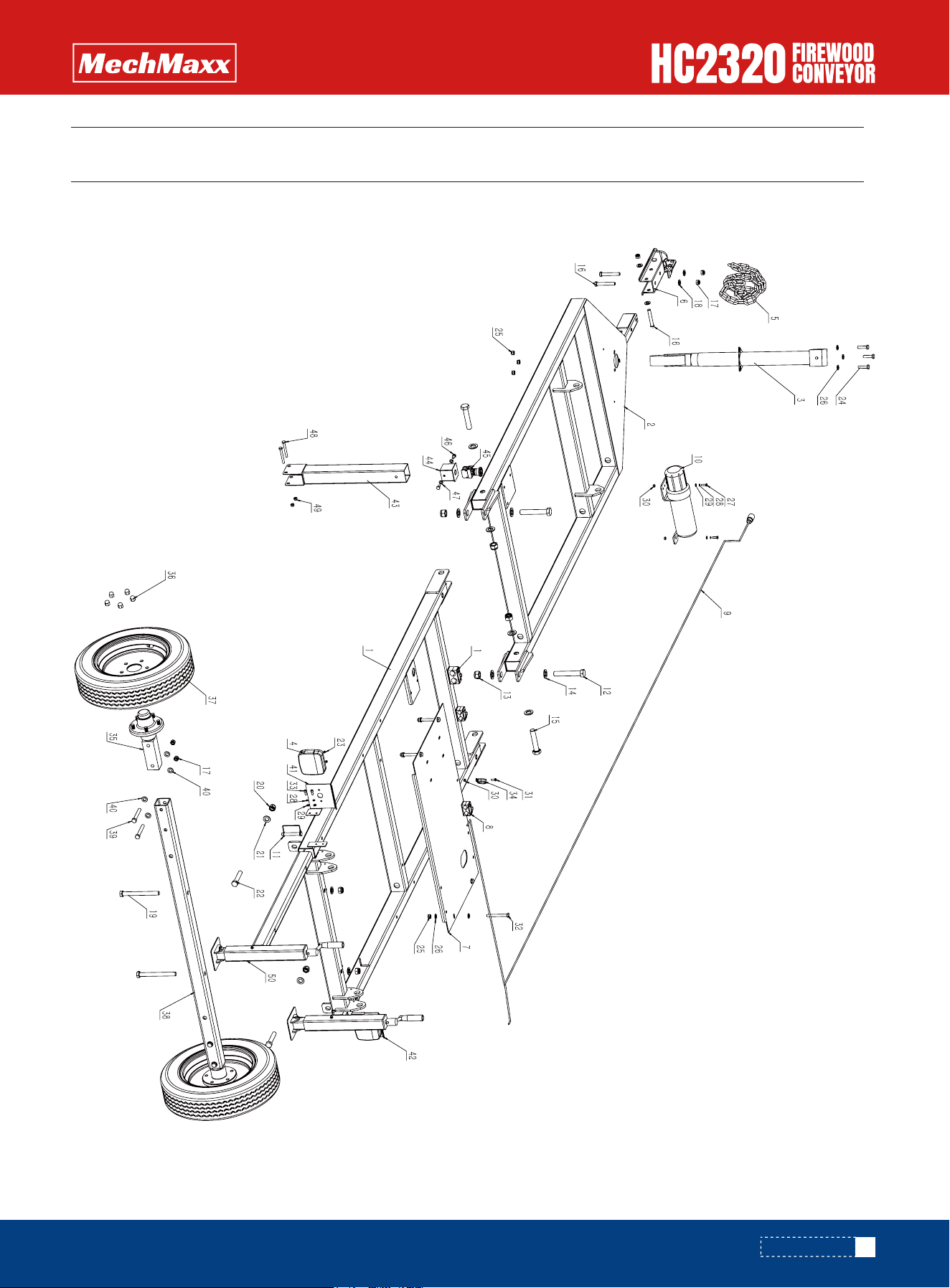
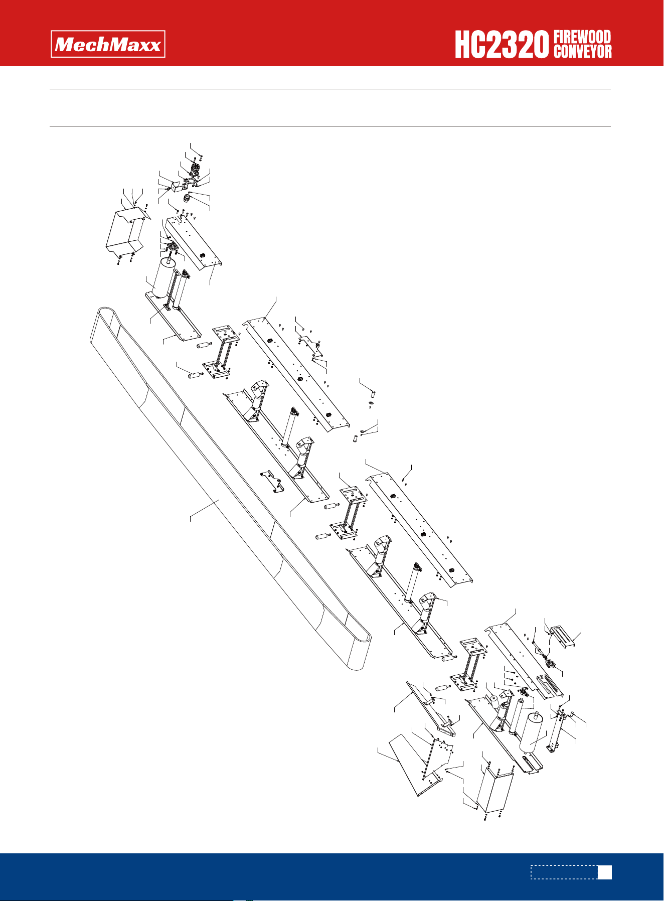
PARTS DIAGRAM
33
PARTS DIAGRAM
www.mechmaxx.com

PARTS LIST
1
1
1
2
1
1
1
1
1
1
2
2
4
8
2
3
7
4
2
4
4
2
4
3
7
11
2
6
6
3
1
No. QTYDESCRIPTION
1
2
3
4
5
6
7
8
9
10
11
12
13
14
15
16
17
18
19
20
21
22
23
24
25
26
27
28
29
30
31
Chassis Weldment 1
Chassis Weldment 2
Trailer Jack
Log Splitter Tail Light
Chain
Trailer Coupler
Engine Mounting Plate
RBP (Retain original abbreviation if it has specific meaning; otherwise clarify)
Tail Light Wiring
Large File Tube
Square Lock Pin
Hex Head Bolt, Full Thread M20×120
Nylon Insert Thin Hex Lock Nut M20
Flat Washer M20
Hex Head Bolt, Full Thread M20×100
Hex Head Bolt M12×80
Nylon Insert Thin Hex Lock Nut M12
Flat Washer M12
Hex Head Bolt M16×160
Nylon Insert Thin Hex Lock Nut M16
Flat Washer M16
Hex Head Bolt M16×85
Nylon Insert Thin Hex Lock Nut M5
Hex Head Bolt, Full Thread M8×30
Nylon Insert Thin Hex Lock Nut M8
Flat Washer M8
Hex Head Bolt M6×20
Spring Washer M6
Flat Washer M6
Nylon Insert Thin Hex Lock Nut M6
Hex Head Bolt, Full Thread M6×16
34
PARTS LIST
www.mechmaxx.com

4
4
1
2
10
2
1
4
8
1
1
1
1
1
2
2
2
2
2
Hex Head Bolt, Full Thread M10×90
Socket Head Cap Screw M6×16
Wire Clip
Hub and Axle Shaft
Hub Nut
Tire
Axle Square Tube
Hex Head Bolt M12×85
Flat Washer M12
Tail Light Bracket L
Tail Light Bracket R
Emergency Stop Rod Weldment
Emergency Stop Switch Box Weldment
Emergency Stop Switch
Hex Head Bolt, Full Thread M8×16
Flat Washer M8
Hex Head Bolt M8×70
Nylon Insert Thin Hex Lock Nut M8
Rear Support Assembly
No. QTYDESCRIPTION
32
33
34
35
36
37
38
39
40
41
42
43
44
45
46
47
48
49
50
35
PARTS LIST
www.mechmaxx.com
PARTS DIAGRAM
36
PARTS DIAGRAM
www.mechmaxx.com

PARTS LIST
10
14
9
1
4
1
8
8
1
1
1
1
1
1
5
3
7
2
4
6
4
4
4
1
1
1
1
1
1
1
1
2
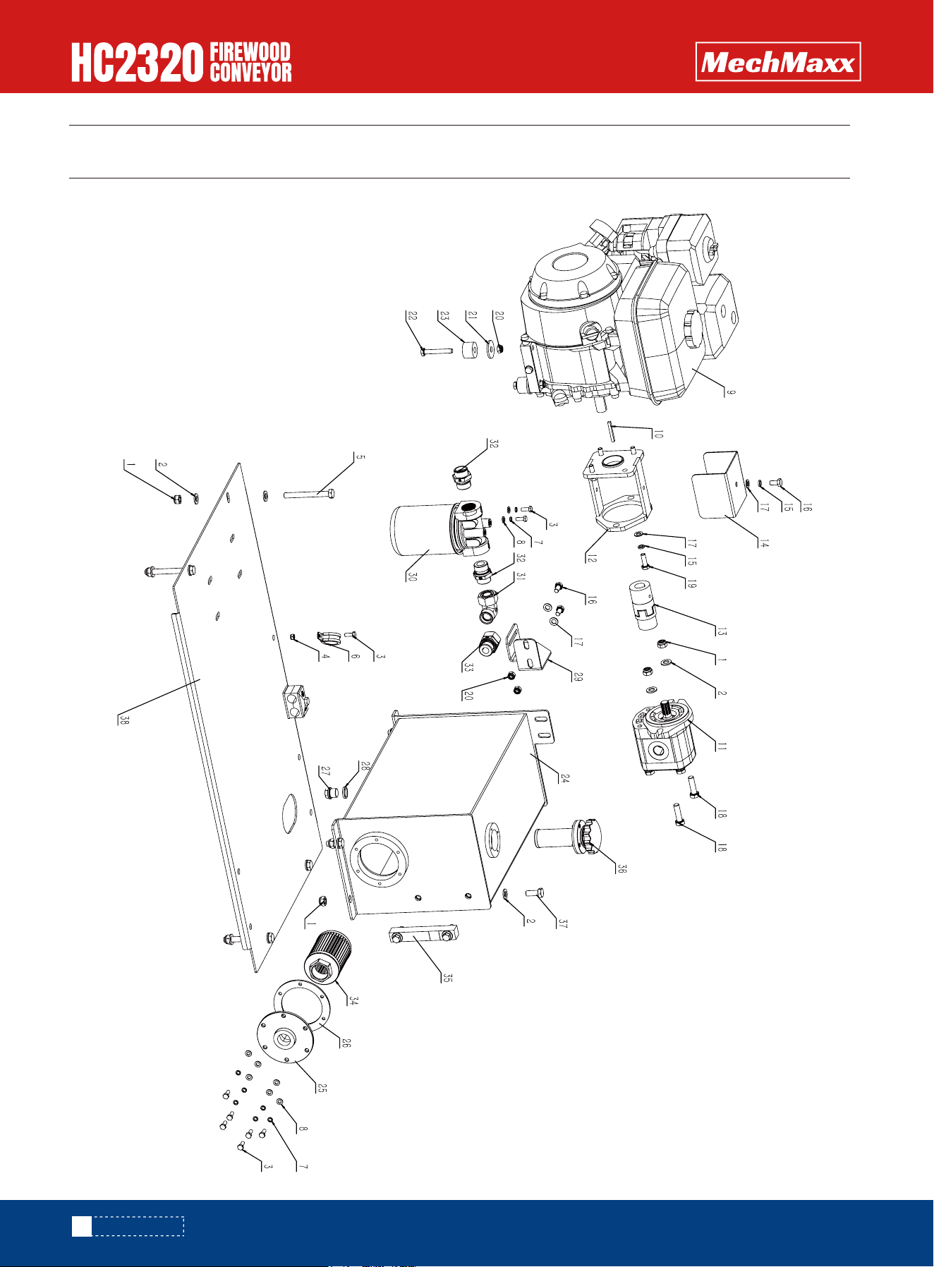
No. QTYDESCRIPTION
1
2
3
4
5
6
7
8
9
10
11
12
13
14
15
16
17
18
19
20
21
22
23
24
25
26
27
28
29
30
31
32
Hexagon Thin Lock Nuts with Non - Metallic Insert M10
Flat Washer 10
Full - thread Hexagon Head Bolt M6×16
Hexagon Thin Lock Nuts with Non - Metallic Insert M6
Full - thread Hexagon Head Bolt M10×90
Wire Clip
Spring Washer 6
Flat Washer 6
Engine
Engine Woodruff Key
Hydraulic Pump
Pump Bracket Welding Assembly
Coupling - Spline (6.5HP - Long Model)
Protective Cover
Spring Washer 8
Full - thread Hexagon Head Bolt M8×16
Flat Washer 8
Full - thread Hexagon Head Bolt M10×35
Hexagon Head Bolt M8×25
Hexagon Thin Lock Nuts with Non - Metallic Insert M8
Extra - large Washer 10
Hexagon Head Bolt M8×55
Engine Rubber Pad
Fuel Tank Welding Assembly
Oil Outlet Flange
Flange Rubber Gasket
Hexagon Pipe Plug with Pipe Thread G3/8A
Combined Washer
Return Oil Filter Bracket
Filter
Elbow Connector
Straight Connector
37
PARTS LIST
www.mechmaxx.com

SLOWFAST
1
1
1
1
4
1
No. QTYDESCRIPTION
33
34
35
36
37
38
Straight Connector
Suction Filter
Level Gauge
Air Filter
Full - thread Hexagon Head Bolt M10×25
Engine Mounting Plate
38
PARTS LIST
www.mechmaxx.com
PARTS DIAGRAM
39
PARTS DIAGRAM
www.mechmaxx.com

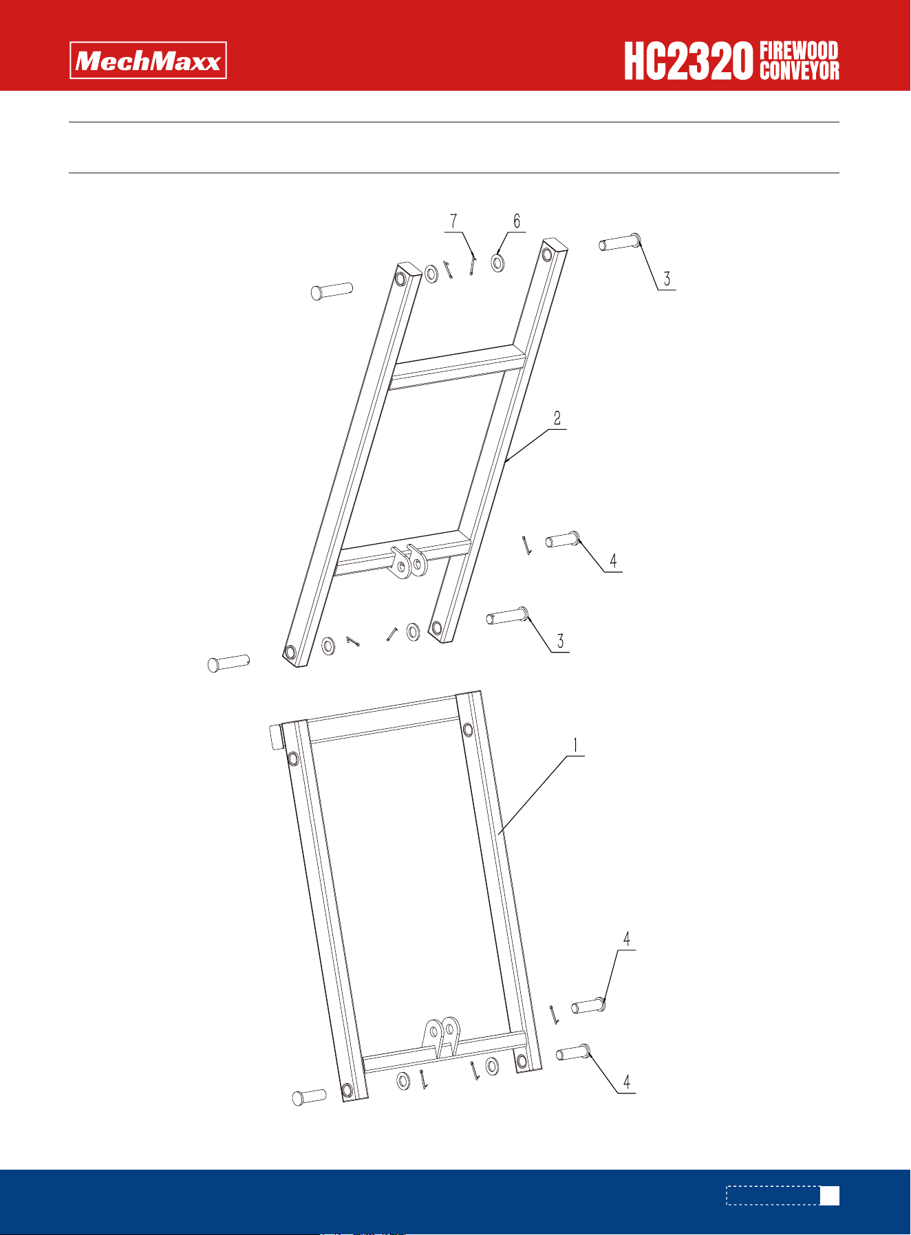
PARTS LIST
1
1
4
4
6
8
No. QTYDESCRIPTION
1
2
3
4
6
7
Bracket welding 2
Bracket welding 1
Pin Shaft 1
Pin Shaft 2
Flat washer Class C 24
Cotter pin 5×50
40
PARTS LIST
www.mechmaxx.com
PARTS DIAGRAM
41
PARTS DIAGRAM
40
58
10
45
41
39
32
42
28
1817
19
39
3143
36
37
9
34
9
38
35
38
30
33
57
25
29
22
46
10
26
56
6059
25
53
22
11
1415
16
13
18 17
19
12
55
59
20
21
9
4
40 10
58
44
48
49
47
51
19
50
3
24
24
27
2
1
23
9
21
8
76
5
52
10
26
54
www.mechmaxx.com

1
15
1
1
1
4
8
16
34
118
2
1
2
2
4
2
9
9
15
4
8
90
4
2
2
92
1
1
1
1
1
1
No. QTYDESCRIPTION
1
2
3
4
5
6
7
8
9
10
11
12
13
14
15
16
17
18
19
20
21
22
23
24
25
26
27
28
29
30
31
32
Idler Bracket Welding
Conveyor Idler
Side Plate Welding
Driven Roller Welding
Mirror Side Plate Welding
Return Roller Welding
Pillow Block Bearing
Carriage Bolt M10×35
Non-Metallic Insert Hex Locking Thin Nut M12
Flat Washer 10
Bearing Protector
Chassis Connection Plate Welding
Insert Ball Bearing with Set Screw
Hex Bolt, Full Thread M20×250
Hex Nut M20
Hex Thin Nut M20
Spring Washer 8
Hex Bolt, Full Thread M8×16
Flat Washer 8
Hex Bolt, Full Thread M12×30
Flat Washer 12
Carriage Bolt M10×25
Idler Bracket Welding
Side Plate
Side Plate 2
Non-Metallic Insert Hex Locking Thin Nut M10
Side Plate 4
Motor Protector
Side Plate 4-R
Drive Roller Welding
Motor Mounting Plate
Hydraulic Motor
PARTS LIST
42
PARTS LIST
www.mechmaxx.com

1
2
1
1
8
8
13
10
2
3
1
1
1
2
1
1
1
6
6
4
3
1
2
1
6
10
3
3
Bracket Welding
Square Flange Bearing
Key Type A 10×8×40
Coupling
Hex Bolt, Full Thread M12×45
Spring Washer 12
Flat Washer 12
Hex Bolt, Full Thread M10×20
Hex Bolt, Full Thread M12×40
Hex Bolt, Full Thread M12×25
Key Type A 8×7×32
Conveyor Rear Baffle Welding
Baffle Plate Welding
Support Base Plate Welding
Hopper Rear Plate
Hopper Side Plate Welding
Mirror Hopper Side Plate Welding
Hex Bolt, Full Thread M8×20
Non-Metallic Insert Hex Locking Thin Nut M8
Hex Bolt, Full Thread M10×25
Bracket Welding-2
Belt
Connecting Shaft 1
Pin shaft 25x85
Vertical Roller
Spring Washer 10
Cotter Pin 5×50
Flat Washer Class C 24
No. QTYDESCRIPTION
33
34
35
36
37
38
39
40
41
42
43
44
45
46
47
48
49
50
51
52
53
54
55
56
57
58
59
60
43
PARTS LIST
www.mechmaxx.com
1
1
1
1
1
1
1
1
1
No. QTYDESCRIPTION
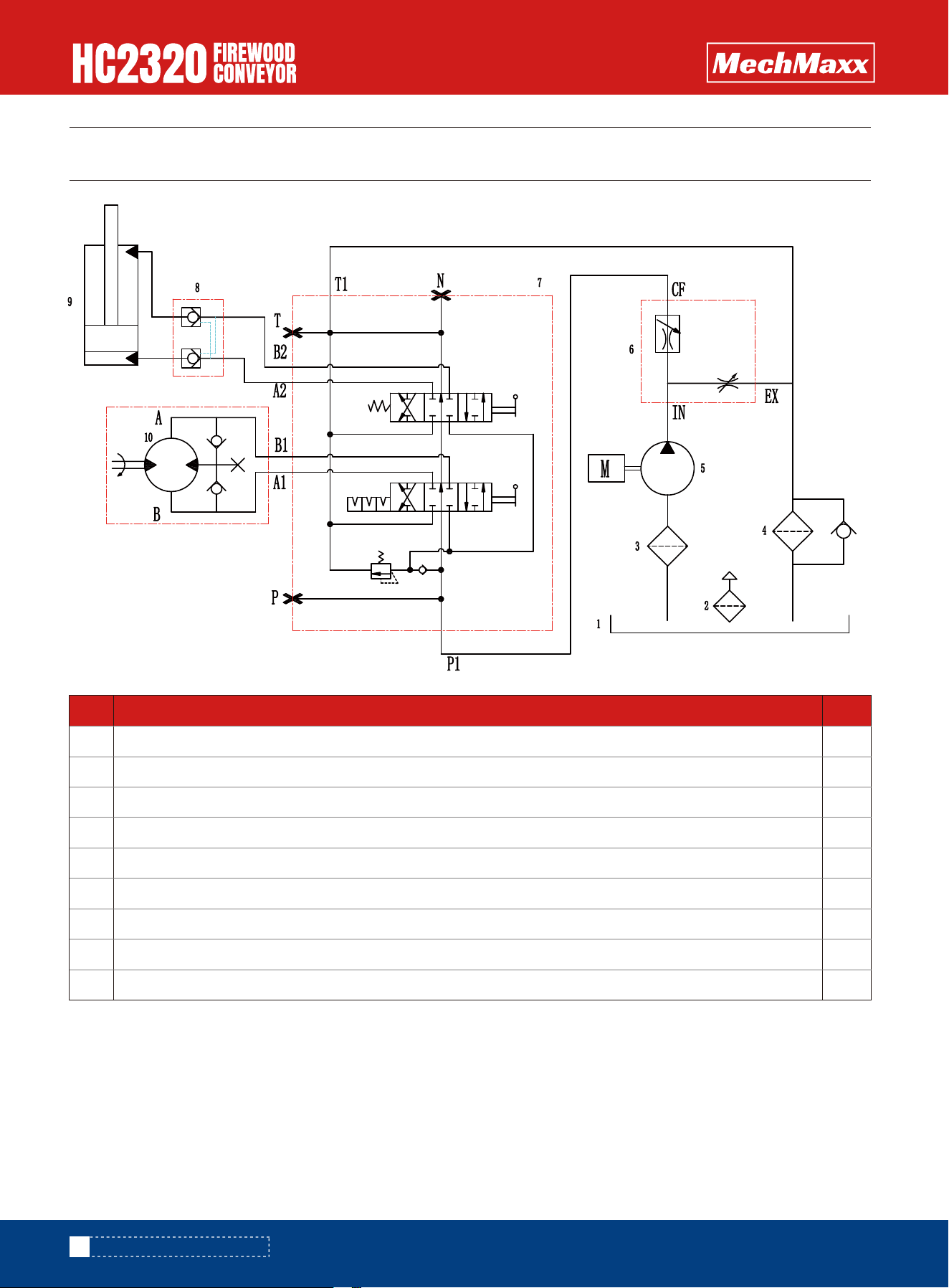
1
2
3
4
5
6
7
8
9
hydraulic oil tank
air filter
suction filter
return filter
oil pump
Flow control valve
Control valve for operation
Hydraulic cylinder
hydraulic motor
HYDRAULIC SCHEMATIC DIAGRAM
44
HYDRAULIC SCHEMATIC DIAGRAM
www.mechmaxx.com