Operator’s Manual
www.mechmaxx.com
WARRANTY


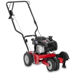
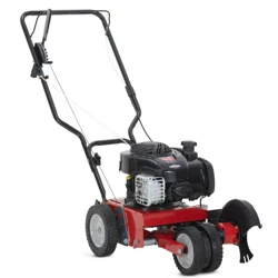
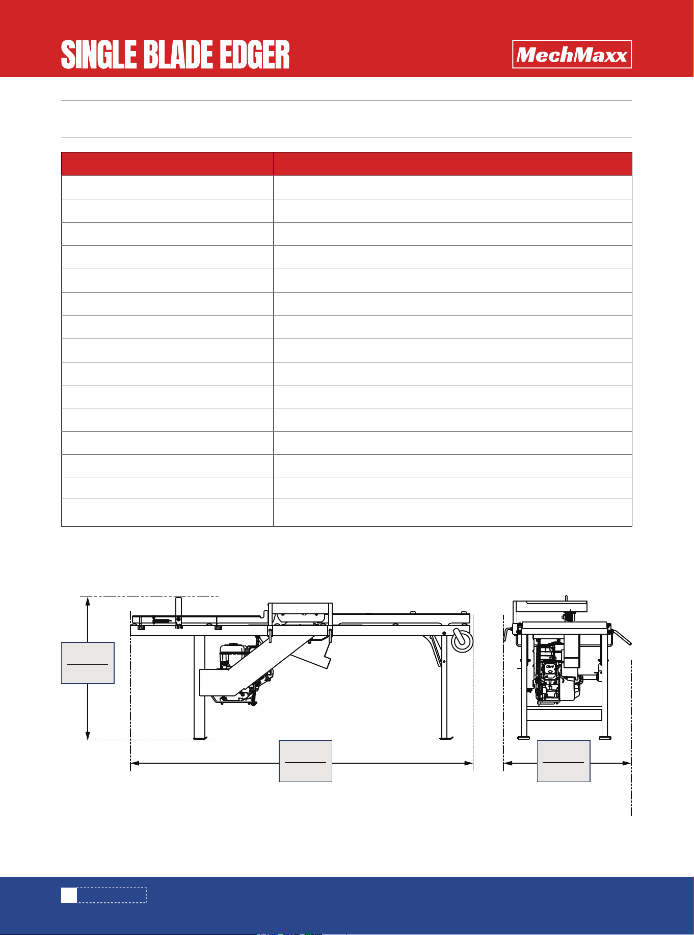
OVERALL DIMENSIONS
TABLE OF CONTENTS
TABLE OF CONTENTS
SPECIFICATIONS
SAFETY SIGNS
SAFETY
1
2
2
SAFETY SYMBOLS
SAFETY INSTRUCTIONS
EDGER SETUP AND TRANSPORTATION SAFETY
4
4
4
EDGER OPERATION SAFETY
5
REFUELING AND ENGINE OPERATION SAFETY
5
SETUP
INSTALL THE ENGINE. TO INSTALL:
ADJUST THE FRONT GUIDE FENCE:
8
9
10
ALIGNMENT
11
OPERATION
13
TRANSPORTING THE EDGER
13
DRIVE SYSTEM
15
FEED TABLE ROLLERS
15
BLADE SYSTEM
15
3
4
7
8
15
INTRODUCTION
SETUP & OPERATION
MAINTENANCE
16
17
PARTS LIST
1
www.mechmaxx.com
TABLE OF CONTENTS
PARTS DIAGRAM
SPECIFICATIONS
OVERALL DIMENSIONS
2
www.mechmaxx.com
SPECIFICATIONS
Engine
Displacement
Blade
Feed System
Thickness
Width
Edger Length
Edger Width
Edger Height
Finish
Machine Warranty (Except the Engine)
Engine Warranty
Package Method
Packing Size
Weight (N.W./G.W.)
DUCAR
270cc; 9HP
10" Carbide Alloy Saw Blades (Diameter 10 in x Thickness 0.063 in; 24 Teeth)
Manual Push Feed Rate- Variable
0.25 in-2.25 in
2 in - 12 in
87.72 in
26 in (34.6 in Overall)
40 in
Powder Coat Paint; Galvanized Steel
2-Years
1-Year
Plywood Package
90 x 32 x 22 in
265 Ibs / 397 Ibs
Model SBE50
1008mm
39.6”
2228mm
87.7”
878mm
34.5”
3
www.mechmaxx.com
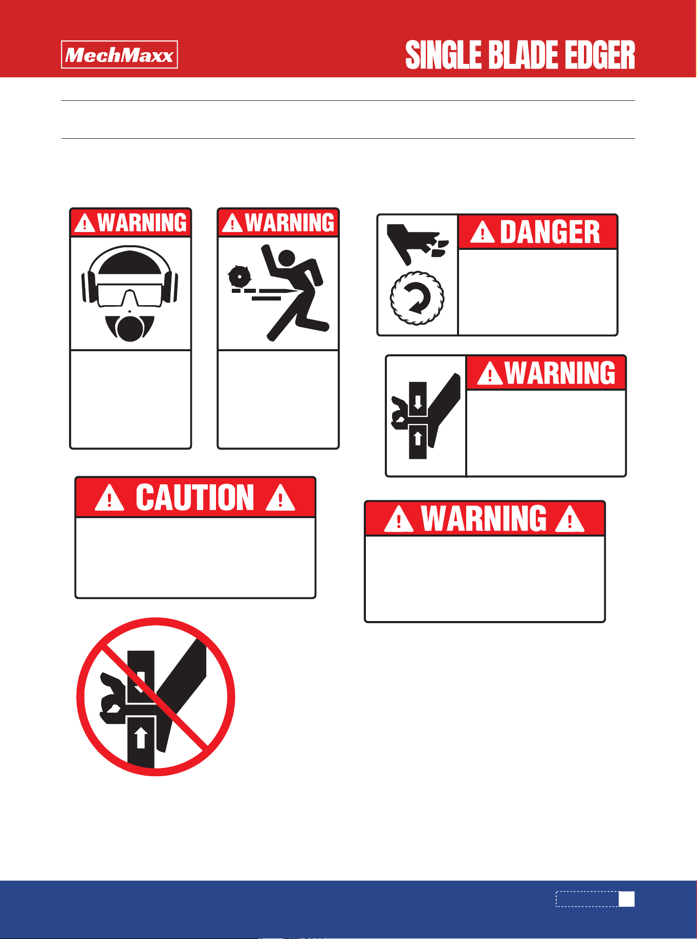
SAFETY SIGNS
The rating plate on your machine may show symbols. These represent important information about the product or instruc-
tions on its use.
SAFETY SIGNS
USE AN APPROPRIATE FUNNEL
TO REFUEL TANK.
REMOVE ANY SPILLED FUEL
FROM AREA BEFORE STARTING
ENGINE.
KEEP AWAY FROM
MOVING BLADE
Do not operate without all guards
and covers in place. Stop machine
before servicing.
Failure to do so will result in
serious injury.
PINCH POINT!
To avoid injury,
keep hands away
from this area.
AVOID RESTING BOARDS OR
OTHER OBJECTS ON COVER.
DAMAGE MAY RESULT
Kickback Hazard
Stay clear of area during
operation. Follow all anti
kickback service and
safety rules.
Failure to do so may
result in serious injury.
STOP!
Always wear eye, ear,
respiration and foot
protection when operating
this machine.
Failure to do so may
result in injury.
4
www.mechmaxx.com
SAFETY SYMBOLS
SAFETY INSTRUCTIONS
EDGER SETUP AND TRANSPORTATION
SAFETY
DANGER!
SAFETY
SAFETY
The following symbols and signal words call your atten-
tion to instructions concerning your personal safety. Be
sure to observe and follow these instructions.
DISPOSE OF SAWING BY-PRODUCTS PROPERLY
Warning stripes are placed on areas where a single decal
would be insufficient. To avoid serious injury, keep out of
the path of any equipment marked with warning stripes.
Read and observe all safety instructions before operating
this equipment! Also read any additional manufacturer’s
manuals and observe any applicable safety instructions
includ�ing dangers, warnings, and cautions.
Always be sure that all safety decals are clean and
readable. Replace all damaged safety decals to prevent
personal injury or damage to the equipment. Contact your
local distributor, or call your Customer Service Represen-
tative to order more decals.
indicates an imminently hazardous situa-
tion which, if not avoided, will result in
death or serious injury.
WARNING!
suggests a potentially hazardous situa-
tion which, if not avoided, could result in
death or serious injury.
WARNING!
Clean sawdust from all guards, vents, con
trol boxes, or any area where sawdust may
gather after every shift. Failure to do so
may result in fire, causing death or
serious injury.
WARNING!
When setting up or transporting the Edger,
avoid areas marked as pinch points.
These are located near the rear folding leg
and the engine pulley. Keep your hands
away from these areas to prevent injury.
WARNING!
Always wear gloves and eye protection
when handling blades. Failure to do so
may result in serious injury.
CAUTION!
refers to potentially hazardous situations
which, if not avoided, may result in minor
or moderate injury or damage to equip-
ment.
CAUTION!
Before operating the Edger, be sure to
removethe shipping block from under the
blade cover. Failure to do so will cause
damage to the machine.
IMPORTANT!
indicates vital information.
NOTE: gives helpful information.
IMPORTANT!
Always properly dispose of all sawing
by-products, including sawdust and other
debris, coolant, oil, fuel, oil filters and fuel
filters.
5
www.mechmaxx.com
EDGER OPERATION SAFETY
REFUELING AND ENGINE OPERATION
SAFETY
SAFETY
DANGER!
Make sure all guards and covers are in
place and secured before operating or
transporting the Edger. Failure to do so
may result in serious injury.
DANGER!
Always be sure the blade is disengaged
and all persons are out of the path of the
blade before starting the engine or motor.
Failure to do so will result in serious
injury.
DANGER!
Always keep hands away from moving
blade. Blade may still be moving even
when the clutch lever is disengaged.
Failure to do so will result in serious
injury.
DANGER!
Keep all persons out of the path of moving
equipment and boards when operating the
Edger or loading boards. Failure to do so
will result in serious injury.
DANGER!
Maintain a clean and clear path for all
necessary movement around the Edger
and lumber stacking areas. Failure to do
so will result in serious injury.
DANGER!
Always be sure the blade is disengaged
and all persons are out of the path of the
blade before starting the engine or motor.
Failure to do so will result in serious
injury.
DANGER!
Always shut off the engine and allow all
moving parts to come to a complete stop
before removing any guards or covers.
Failure to do so will result in serious
injury.
WARNING!
Always shut off the engine to stop the
blade whenever the Edger is not in use.
Failure to do so may result in serious
injury.
WARNING!
Always wear eye, ear, respiration, and
foot protection when operating the Edger.
Failure to do so may result in serious
injury.
WARNING!
Secure all loose clothing and jewelry
before operating the Edger. Failure to do
so may result in serious injury or death.
WARNING!
Kickback Hazard. Stay clear of area
during operation. Follow all anti-kickback
service and safety rules. Failure to do so
may result in serious injury.
WARNING!
Store gasoline away from sawdust and
other flammable materials. Also remove
sawdust from above the engine tank
before refueling. Failure to do so may
result in serious injury.
WARNING!
Use an appropriate funnel to refuel tank.
Remove any spilled fuel from area before
starting engine. Failure to do so may
result in serious injury.
WARNING!
Do not for any reason adjust the engine
drive belts or belt support bracket with the
engine running. Doing so may result in
serious injury.
CAUTION!
Avoid resting boards or other objects on
the blade guard. Damage to the guard may
result.
6
www.mechmaxx.com
SAFETY
WARNING!
Always wear proper and necessary safety
equipment when performing service func-
tions. Proper safety equipment includes
eye protection, breathing protection, hand
protection and foot protection.
WARNING!
The engine exhaust from this product
contains chemicals known to the State of
California to cause cancer, birth defects
or other reproductive harm.
CAUTION!
Do not lift the engine by the carburetor
when replacing the drive belt. Damage to
the engine may result.
7
www.mechmaxx.com
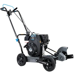
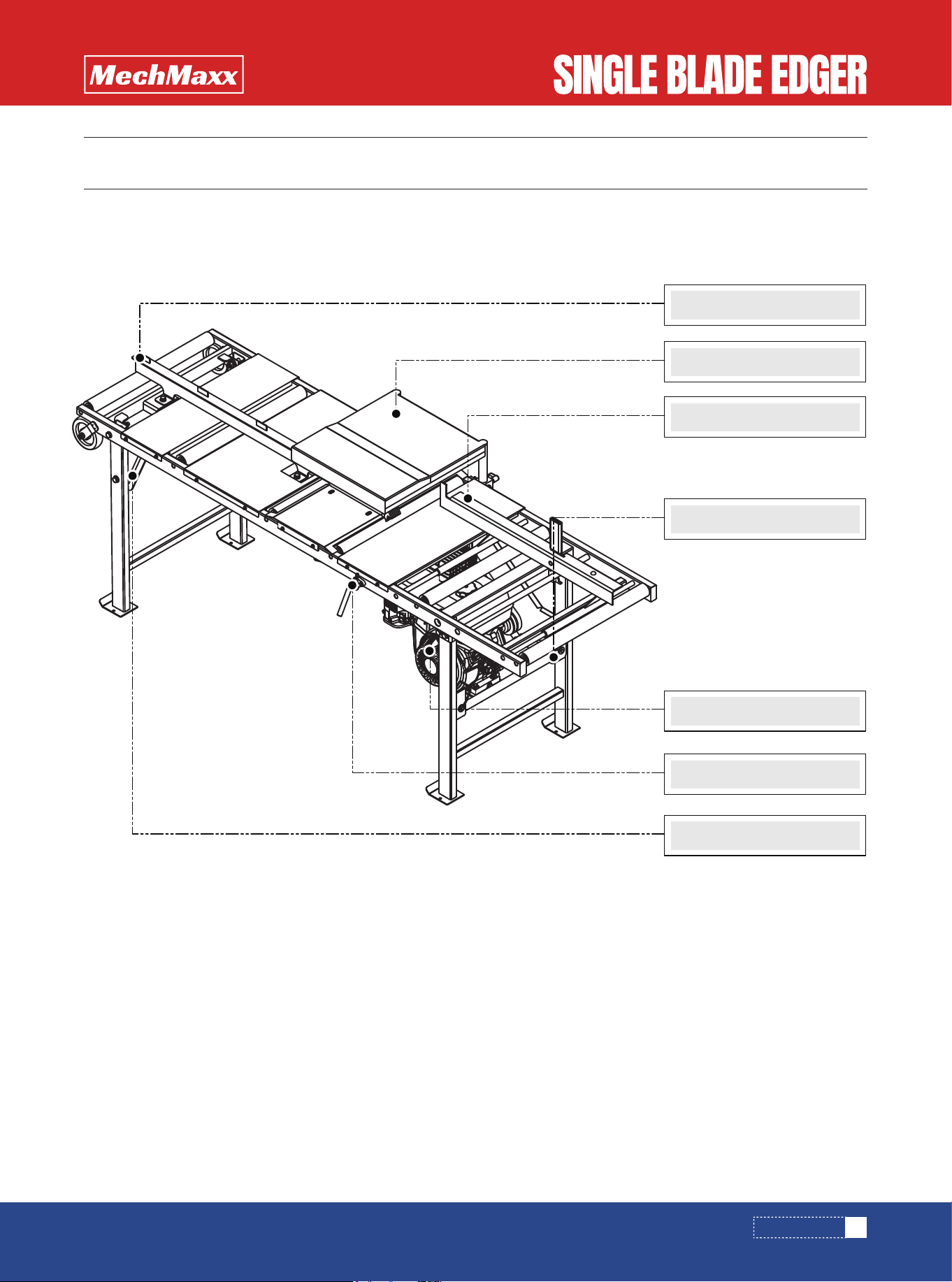
INTRODUCTION
INTRODUCTION
The information and instructions given in this manual do not amend or extend the limited warranties for the equipment
given at the time of purchase.
Important components of the edger are identified below.
Front Fence
Engine Assembly
Clutch Lever
Rear Leg Lock Bracket
Rear Fence
Top Blade Guard
U-Brackets & Lock Pins
8
www.mechmaxx.com
SETUP
SETUP & OPERATION
SETUP & OPERATION
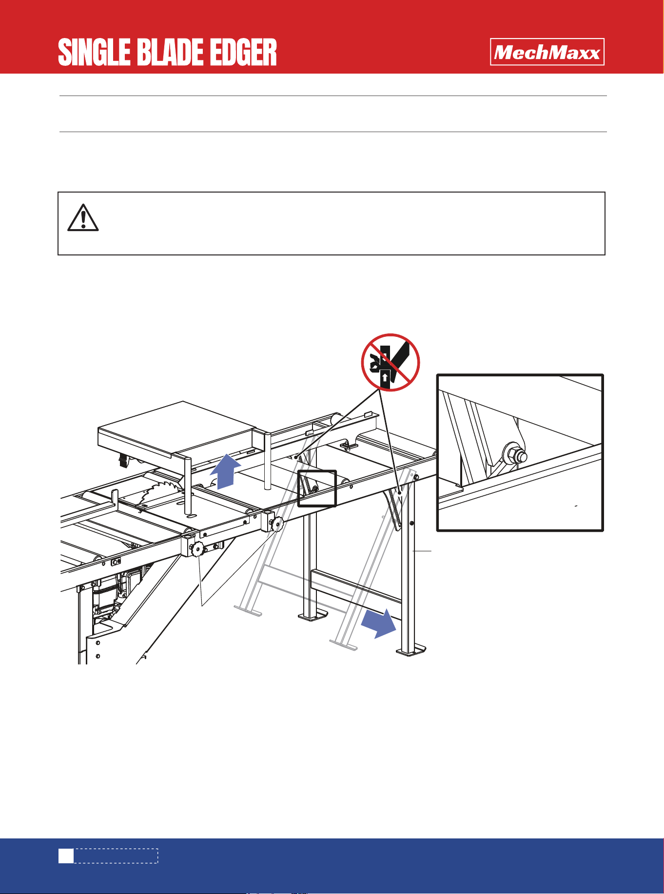
Swing the leg all the way down until they lock in position. Be sure the pivot bolts seat in the brace notches.
WARNING!
When setting up or transporting the Edger, avoid areas marked as pinch points. These are located
near the rear folding leg and the engine pulley. Keep your hands away from these areas to prevent
injury.
Loosen
Mount Knobs
Swing rear leg
down until locked
in position
(See Detail)
DETAIL
9
www.mechmaxx.com
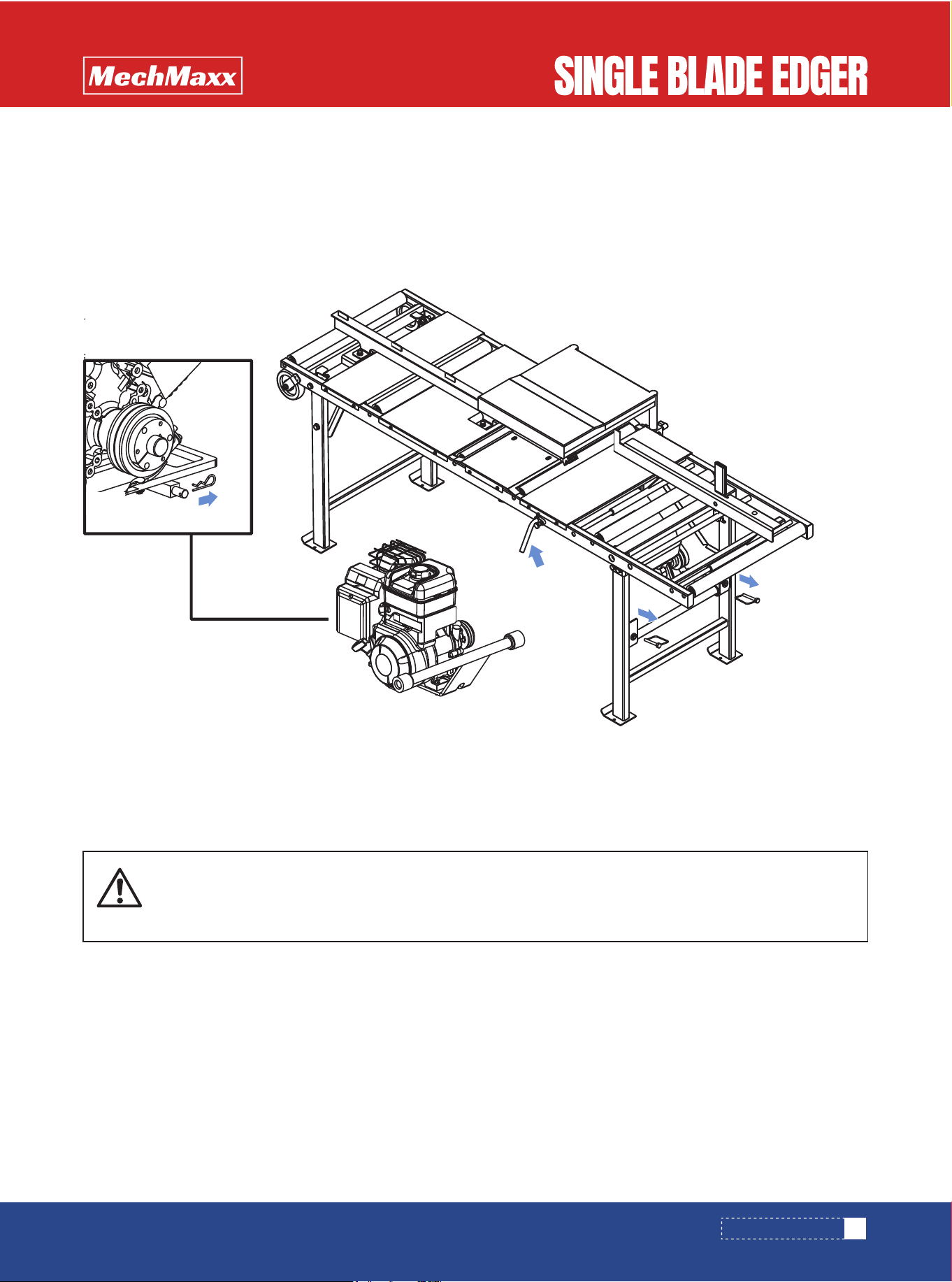
INSTALL THE ENGINE. TO INSTALL:
SETUP & OPERATION
• Position the engine beneath the Edger.
• Remove the U-bracket lock pins and clutch retaining pin. Raise the clutch handle.
• Place the ends of the engine mounting bar in the U-brackets and reinstall the U-bracket lock pins.
• Position the drive belt around the engine pulley.
• Connect the clutch linkage to the motor mount plate pin and replace the retaining pin.
WARNING!
When setting up or transporting the Edger,avoid areas marked as pinch points. These are located
near the rear folding leg and the engine pulley. Keep your hands away from these areas to prevent
injury.
Remove U-bracket
lock pins
Raise clutch
handle
Remove clutch
retaining pin
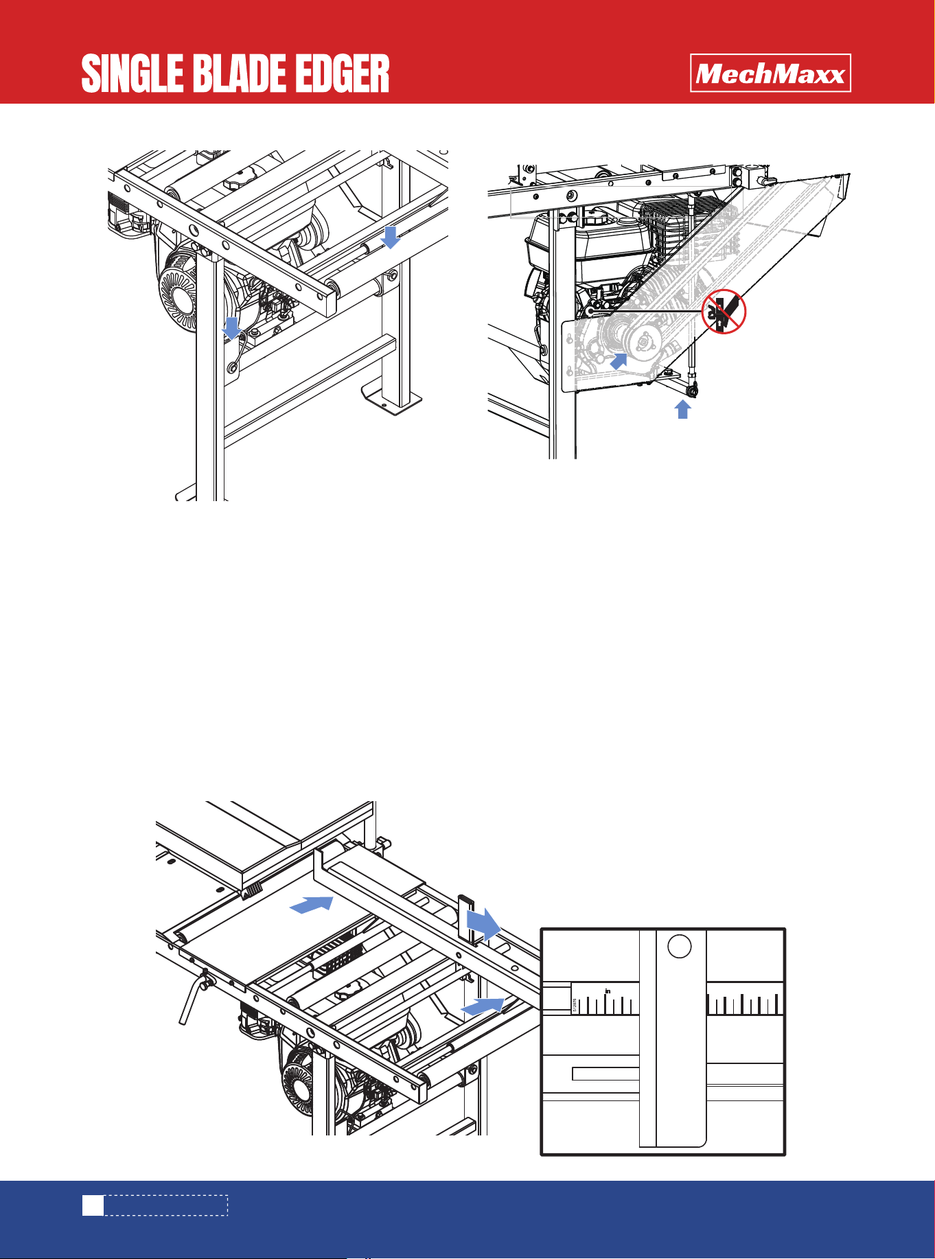
ADJUST THE FRONT GUIDE FENCE:
SETUP & OPERATION
• The guide scale shows how many inches the front fence is from the blade. This helps you to determine the width of
lumber you will be sawing.
• For example, if you wish to cut 2" lumber, you will need to adjust the front fence 2" from the blade, or to the 2" mark on
the guide scale. The front fence can be adjusted as often as necessary.
• The front fence can be adjusted from 0 to 12". To adjust the front fence, pull the fence lock handle and slide the fence
to the desired position. Release the fence lock handle to lock the fence into place.
If necessary, level the Edger by shimming under the leg foot pads.
NOTE: Adjust the rear of the edger slightly lower than the front to allow gravity to assist in feeding boards.
10
www.mechmaxx.com
Place mounting bar
in U-brackets &
replace lock pins
Pull fence lock handle
back and move fence
to desired board width
1
5
2
6
Position belt around engine
pulley. Connect clutch linkage
to mount pin and replace
retaining pin
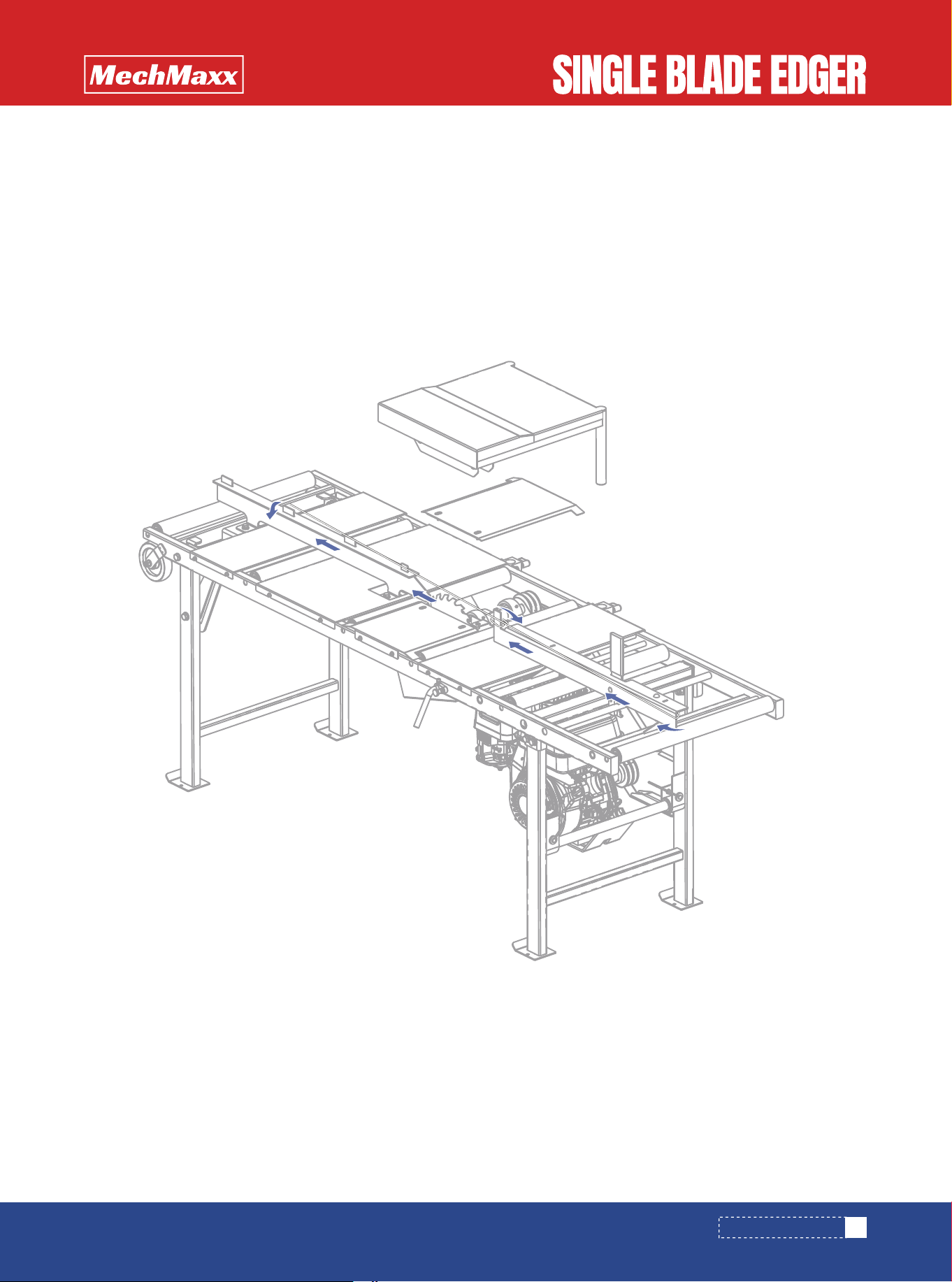
ALIGNMENT
Proper machine alignment is important for optimum cutting performance. Check machine alignment often and adjust as
necessary. To check:
1. Adjust the front fence to the 5" position. Be sure the blade clutch handle is disengaged.
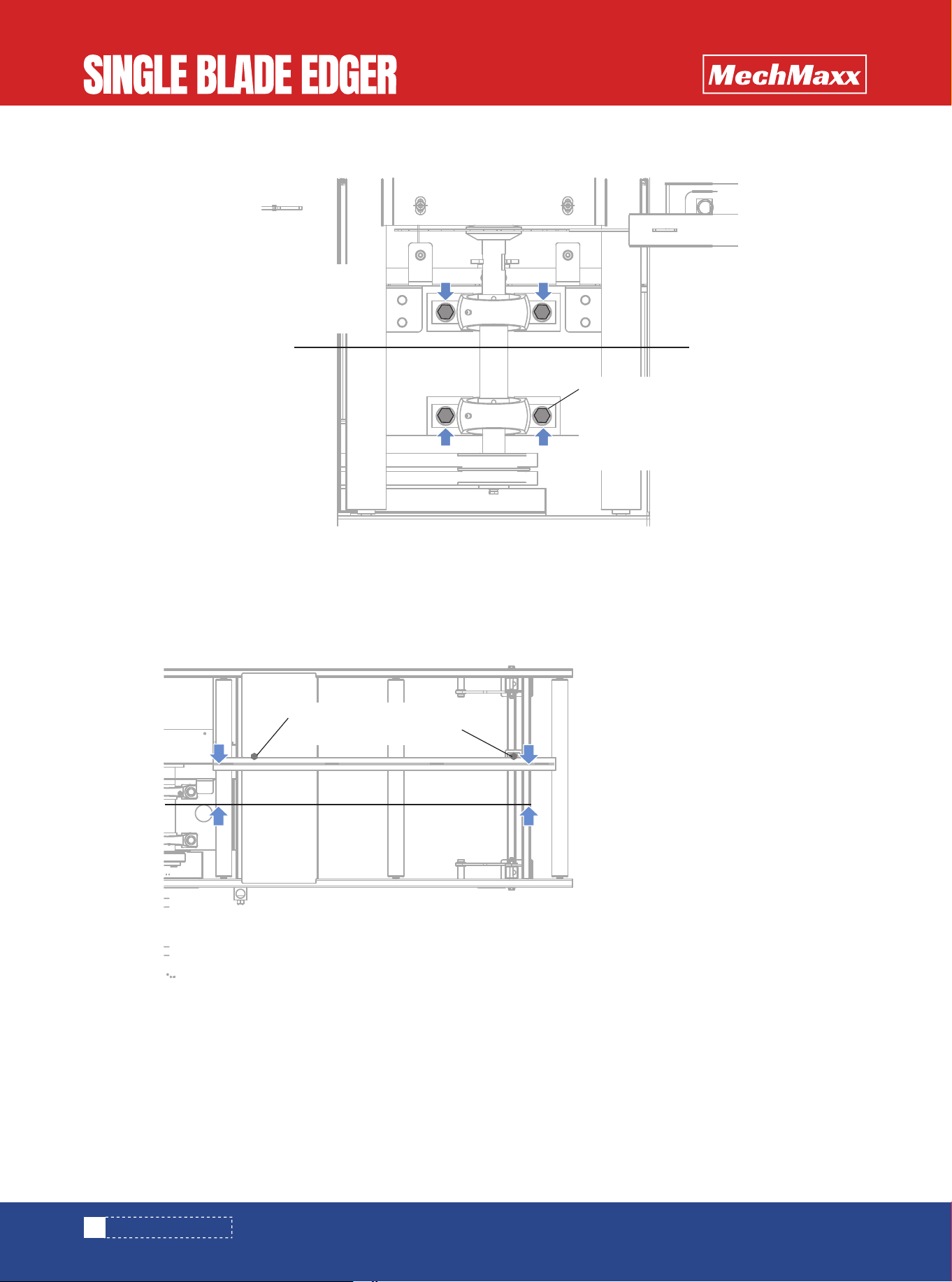
2. Loosen the mount knobs and remove the blade guard. Unscrew and remove the blade bearing cover plate.
3.Tie one end of a string (string must be approximately 11’ or longer in length) to the front fence tab. Route the string
around the front end of the fence. Pulling the string tight, align it with the face of the front fence along the entire length
of fence.
4. Use a C-clamp to secure the string to the rear frame cross tube, maintaining the string alignment to the front fence.nt
end of the fence. Pulling the string tight, align it with the face of the front fence along the entire length of fence.
5. Measure the distance between the face of the blade and the string at each end of the blade. The measurements should
be the same as the front fence setting (5 inches) at both ends.
11
www.mechmaxx.com
SETUP & OPERATION
Clamp string to
rear cross tube
Remove top blade
guard & bearing
cover plate
Tie string around fence
tab and route
around front face of fence
12
www.mechmaxx.com
6.Measure the distance between the face of the rear fence and the string at each end of the rear fence.
The measurements should be the same as the front fence setting (5 inches).
If necessary, loosen the locking nuts and move the rear fence rail as necessary. Retighten the nuts.
SETUP & OPERATION
Loosen rear fence mount
bolts to adjust fence
With string flat against front
fence, measure the distance
from the string to rear fence
at both ends
With string flat against front
fence, measure the distance
from the string to the blade
tube at both ends
Loosen blade shaft
bearing mount bolts
to adjust position
of blade
13
www.mechmaxx.com
OPERATION
TRANSPORTING THE EDGER
1.Make sure the Edger has been properly set up and the
blade guard and fences have been properly adjusted to cut
your size boards.
2.Check the alignment.
3.Start the engine:
5.TO SHUT OFF THE ENGINE, turn the engine switch to the
OFF position.
Follow these steps to transport the Edger in a pickup
truck (minimum 8’ bed required):
4. Begin edging:
• Making sure the clutch lever is disengaged (in the
raised position), turn the engine switch located on top
of the engine to the ON position.
• Move the choke to the START position.
• Pull the engine cord slowly until you feel resistance,
then pull the cord quickly to start the engine. Repeat
with the choke opened slightly if necessary.
• When the engine starts, slowly open the choke all the
way by moving the choke lever to the OFF position.
• Position a board against the front fence. Push the
board into the blade until the board begins to feed
itself.
• Measure the edged board to make sure the front fence
is adjusted properly. If the measurements are not
correct, readjust the front fence and repeat step 4.
• Lower the clutch lever to engage the blade. Push the
lever down until the clutch linkage locks into the
engaged position.n.
DANGER!
Always be sure the blade is disengaged
and all persons are out of the path of the
blade before starting the engine or motor.
Failure to do so will result in serious
injury.
DANGER!
Make sure all guards and covers are in
place and secured before operating or
transporting the Edger. Failure to do so
may result in serious injury.
DANGER!
Always keep hands away from moving
blade. Blade may still be moving even
when the clutch lever is disengaged.
Failure to do so will result in serious injury
DANGER!
Keep all persons out of the path of moving
equipment and boards when operating the
Edger or loading boards. Failure to do so
will result in serious injury.
DANGER!
Maintain a clean and clear path for all
necessary movement around the Edger
and lumber stacking areas. Failure to do
so will result in serious injury.
WARNING!
Always wear eye, ear, respiration, and
foot protection when operating the Edger.
Failure to do so may result in serious
injury.
WARNING!
Always shut off the engine to stop the
blade whenever the Edger is not in use.
Failure to do so may result in serious
injury.
WARNING!
When setting up or transporting the Edger,
avoid areas marked as pinch points.
These are located near the rear folding
legs and the engine pulley. Keep your
hands away from these areas to prevent
injury.
WARNING!
Secure all loose clothing and jewelry
before operating the Edger. Failure to do
so may result in serious injury or death.
CAUTION!
Avoid resting boards or other objects on
the blade guard. Damage to the guard may
result.
SETUP & OPERATION

14
www.mechmaxx.com
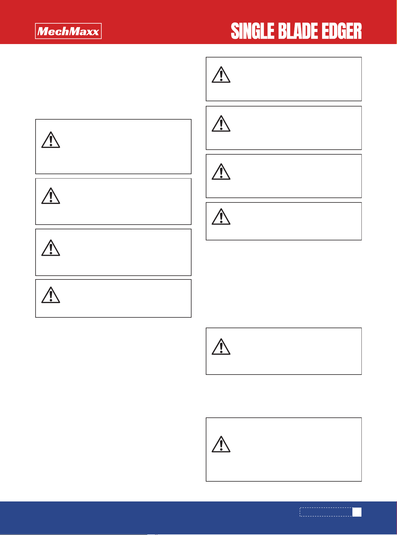
1. Make the Edger lighter and more portable by removing
the engine. To remove, disconnect the clutch linkage from
the motor mount pin and remove the lock pins from the
Edger U-brackets. Lift the engine up and remove it from
the Edger. Reinstall the lock pins into the U-brackets.
2. Back the truck to the rear of the edger until the truck
bed is positioned under the rear of the Edger frame. Lift
the weight from the rear Edger leg and fold the leg up to
the Edger frame, allowing rollers at the rear of the Edger
to rest on the bed of the truck.
3. Slide the Edger into the truck. Secure as necessary for
transport.
SETUP & OPERATION
15
www.mechmaxx.com
MAINTENANCE
MAINTENANCE
1. Refer to the engine manufacturer’s owner’s manual for
engine maintenance recommen dations and instructions.
2. Check the drive belt for wear every 8 hours of operation.
Replace as necessary.
Check the feed table rollers for wear every 25 hours of
operation. Rollers should spin freely, without too much
play. To replace, cut the old roller in half and remove it
from the edger. Install the new spring-loaded roller.
1.Check the blade every 8 hours of operation. Resharpen
or replace as needed
To replace, loosen the two mount knobs and remove the
top blade guard. Unscrew and remove the blade filler
plate. Raise the lock bracket to lock the blade shaft in
place. Through the access hole in the blade guard, remove
the blade retainer bolt (left-hand threads, turn clockwise)
and washer. Remove the retainer plate and blade. Install
the new blade. Reinstall the washer and the nut. Replace
the blade filler plate and the top blade guard. Lower the
lock bracket to release the blade shaft.
3.Over time, the drive belt will stretch. To tighten the belt,
adjust the clutch turnbuckle. If no more adjustment is
available, replace the belt.
Loosen the jam nuts at the upper and lower rod ends
(note the lower jam nut has left-hand threads). Turn the
clutch turnbuckle to the left as viewed to lengthen.
DANGER!
Always shut off the engine and allow all
moving parts to come to a complete stop
before removing any guards or covers.
Failure to do so will result in serious
injury.
WARNING!
Always wear gloves and eye protection
when handling bandsaw blades. Changing
blades is safest when done by one person!
Keep all other persons away from area
when coiling, carrying or changing a
blade. Failure to do so may result in
serious injury.
CAUTION!
Do not lift the engine by the carburetor
when replacing the drive belt. Damage to
the engine may result.
DRIVE SYSTEM
FEED TABLE ROLLERS
BLADE SYSTEM
Upper rod end
(right-hand threads)
Turn turnbuckle
to lengthen
Lower rod end
(left-hand threads)
Remove top blade
guard and blade
filler plate
Raise lock bracket
to lock blade
shaft in place
Remove blade
retainer bolt, washer
and plate
16
www.mechmaxx.com
MAINTENANCE
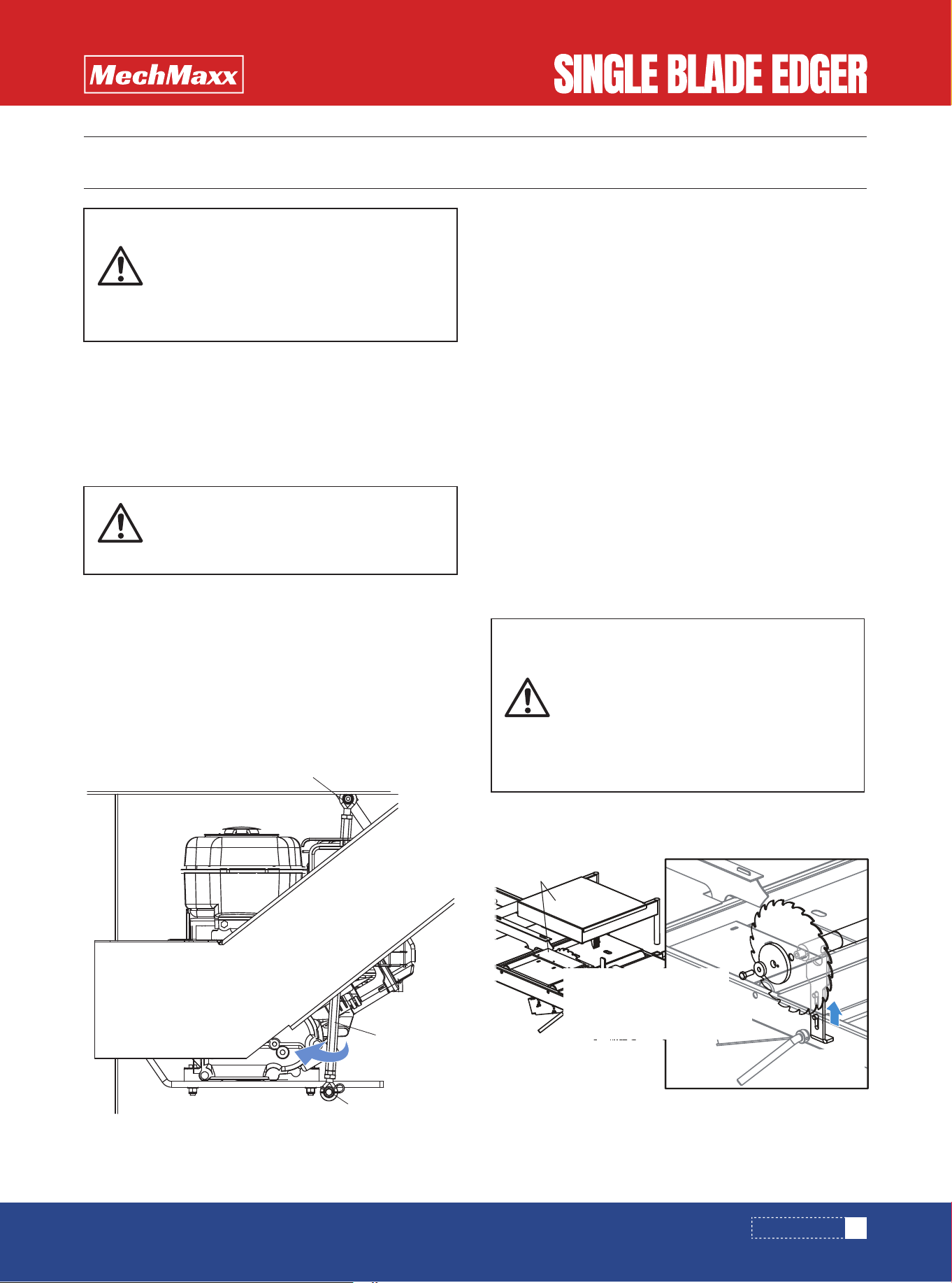
2.Check blade bearing performance every 50 hours of
operation. Replace as necessary.
3.Lubricate the blade bearings every 400 hours of opera-
tion. Use a high-quality synthetic grease such as Amoco
Rycon #2 or Chevron SRI #2.
Access the bearing grease fittings through the holes in
the blade bearing cover plate.
Blade bearing grease
fitting access holes
17
www.mechmaxx.com
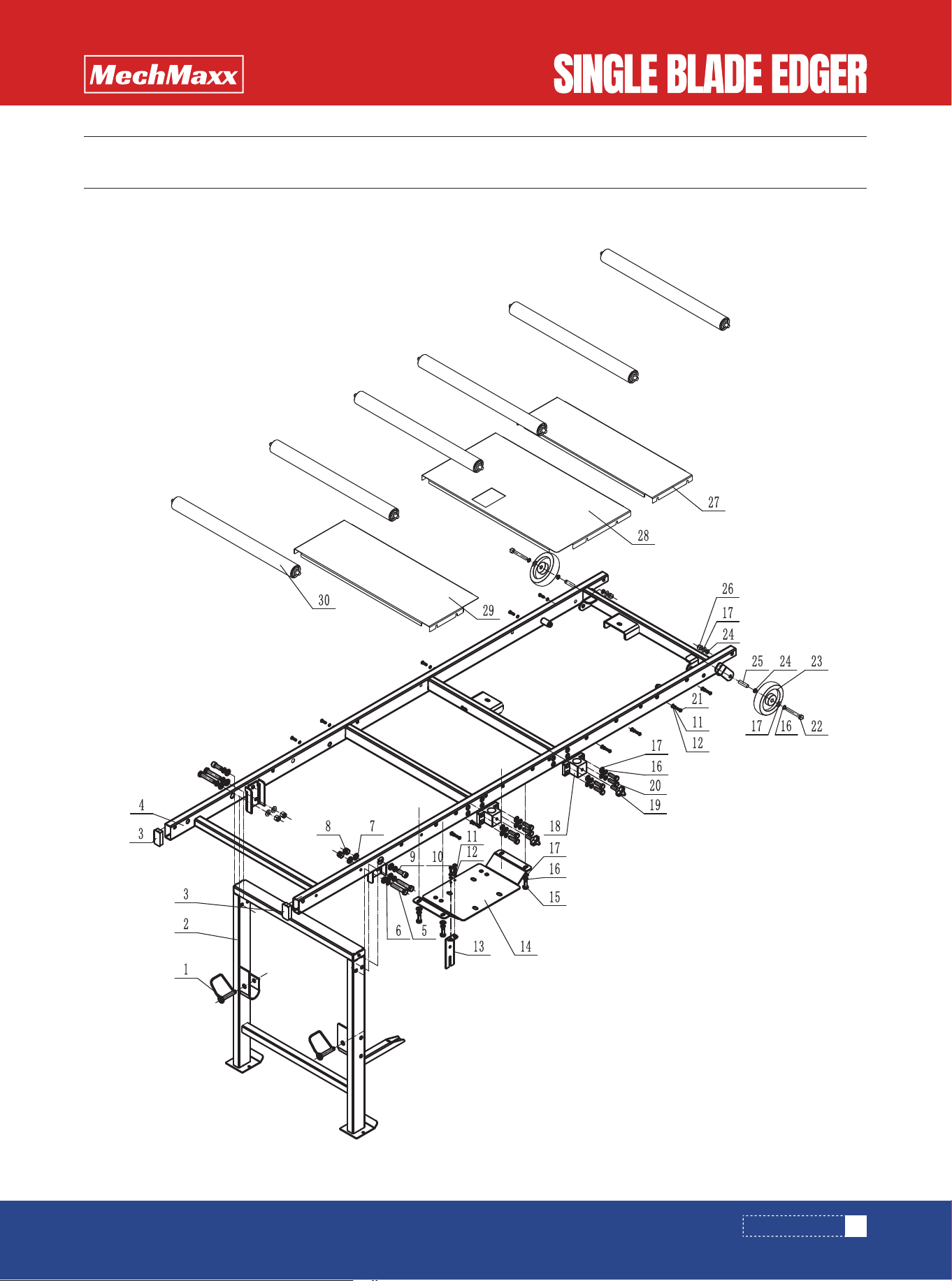
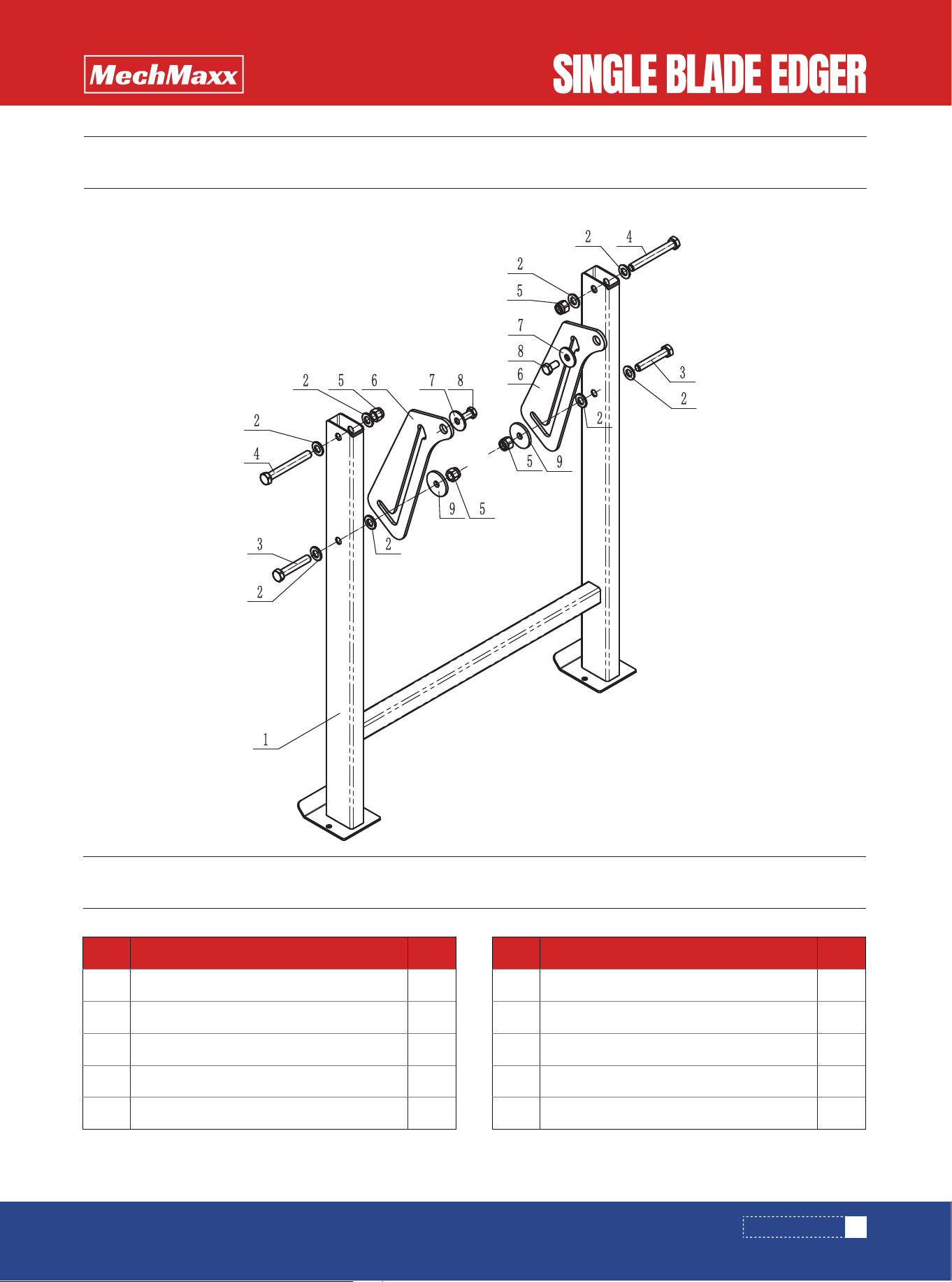
PARTS DIAGRAM
PARTS DIAGRAM

18
www.mechmaxx.com
PARTS LIST
PARTS LIST
No. Description Qty.
1
2
3
4
5
6
7
8
9
10
11
12
13
14
15
16
17
18
19
20
21
22
23
24
25
26
27
28
29
FBow-shaped safety spring lock pin 12X70
Front leg weldment
Plastic square pipe plug 60X30
Frame weldment
Hexagonal head bolt M12×75
Elastic washer 12
Flat washer 12
Hexagonal self-locking nut M12
Inner hexagonal cylindrical head screw M12×30
Hexagonal head bolt full thread M6×20
Elastic washer 6
Flat washer 6
Wrench slide
Bearing seat fixing plate
Hexagonal head bolt full thread M10×25
Elastic washer 10
Flat washer 10
Stand-mounted pipe fixing piece
Adjustable locking handle M10*R80*25
Hexagonal head bolt full thread M10×35
Inner hexagonal semicircular head screw M6×20
Hexagonal head bolt M10×70
5-inch nylon wheel
Nylon wheel adjustment washer
Nylon wheel sleeve
Hexagonal self-locking nut M10
Cover 3
Cover 1
Cover 2
Unpowered driven rod
2
1
2
1
4
6
10
4
2
2
14
14
1
1
4
14
16
2
2
8
12
2
2
8
2
2
1
1
1
6
30
No. Description Qty.
19
www.mechmaxx.com
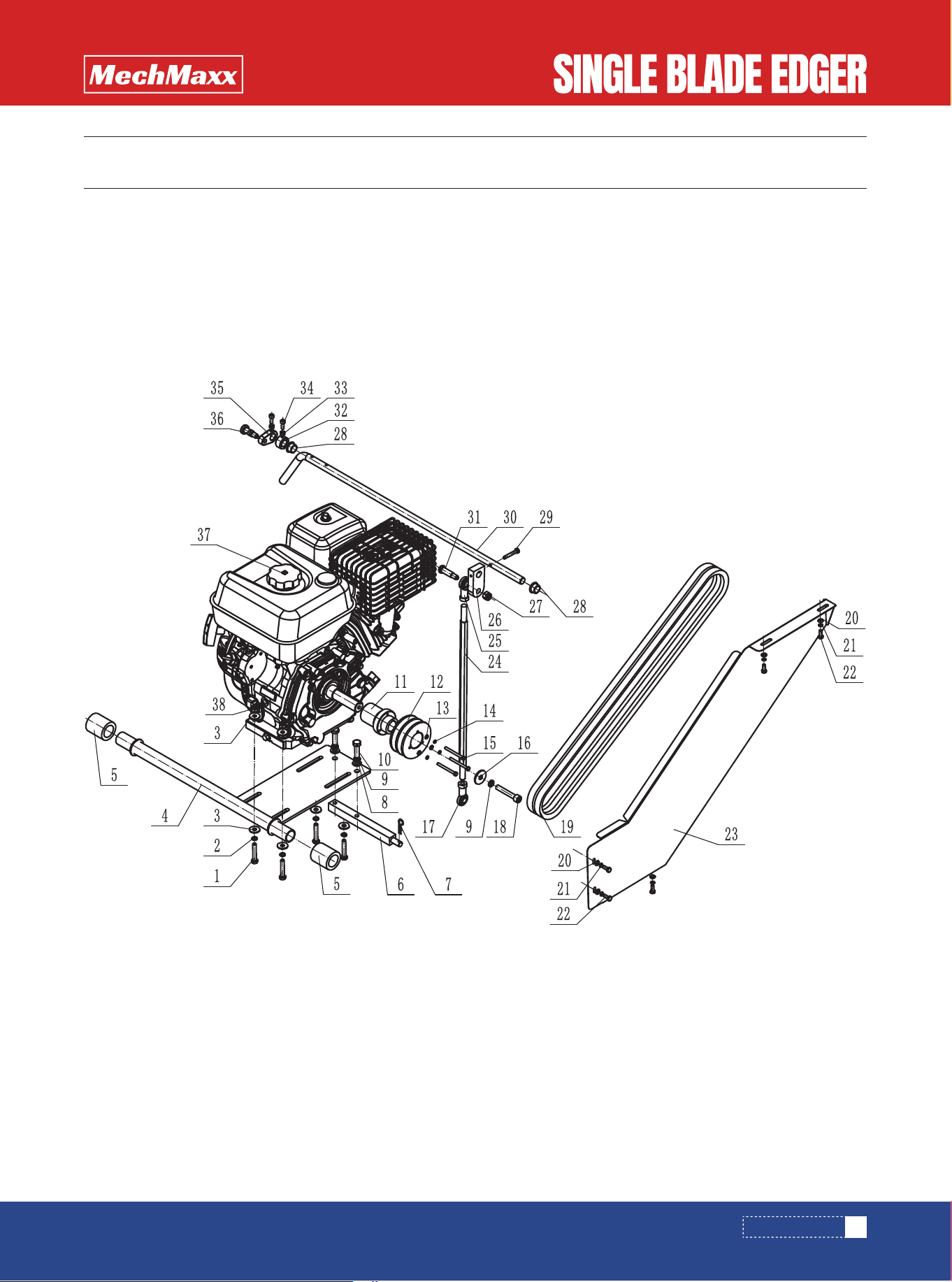
PARTS DIAGRAM
PARTS DIAGRAM
20
www.mechmaxx.com
PARTS DIAGRAM
PARTS LIST
1
2
3
4
5
6
7
8
9
10
11
12
13
14
15
16
17
18
19
20
21
22
23
24
25
26
27
28
29
4
4
8
1
2
1
1
2
3
2
1
1
3
3
3
1
1
1
2
5
5
5
1
1
1
1
1
2
1
1
1
1
2
2
1
1
1
4
30
31
32
33
34
35
36
37
38
Hexagon bolt M8×45
Elastic washer 8
Large flat washer Φ8
Engine hanging shaft weldment
Polyurethane sleeve
Joint bearing column
R pin 3*50
Flat washer 10
Elastic washer 10
Hexagon bolt full thread M10×35
Pulley sleeve
Pulley 2
Flat washer 5
Elastic washer 5
Hexagon bolt M5×55
Large washer 10×35X3
Fisheye joint bearing
Hexagon socket head screw M10X60
V-belt
Large flat washer Φ6
Elastic washer 6
Hexagon bolt full thread M6×16
Pulley cover
Tie rod
Fisheye joint bearing
Push block
Hexagon lock nut M10
Oil-containing copper sleeve
Hexagon bolt full thread M6×40
Tension rod
Plug bolt 12X30-M10
Lock sleeve
Hexagonal nut M6
Hexagon socket head screw M6X16
Lock plate
Index pin
Dajiang gasoline engine
Hexagonal lock nut M8
No. Description Qty. No. Description Qty.
21
www.mechmaxx.com
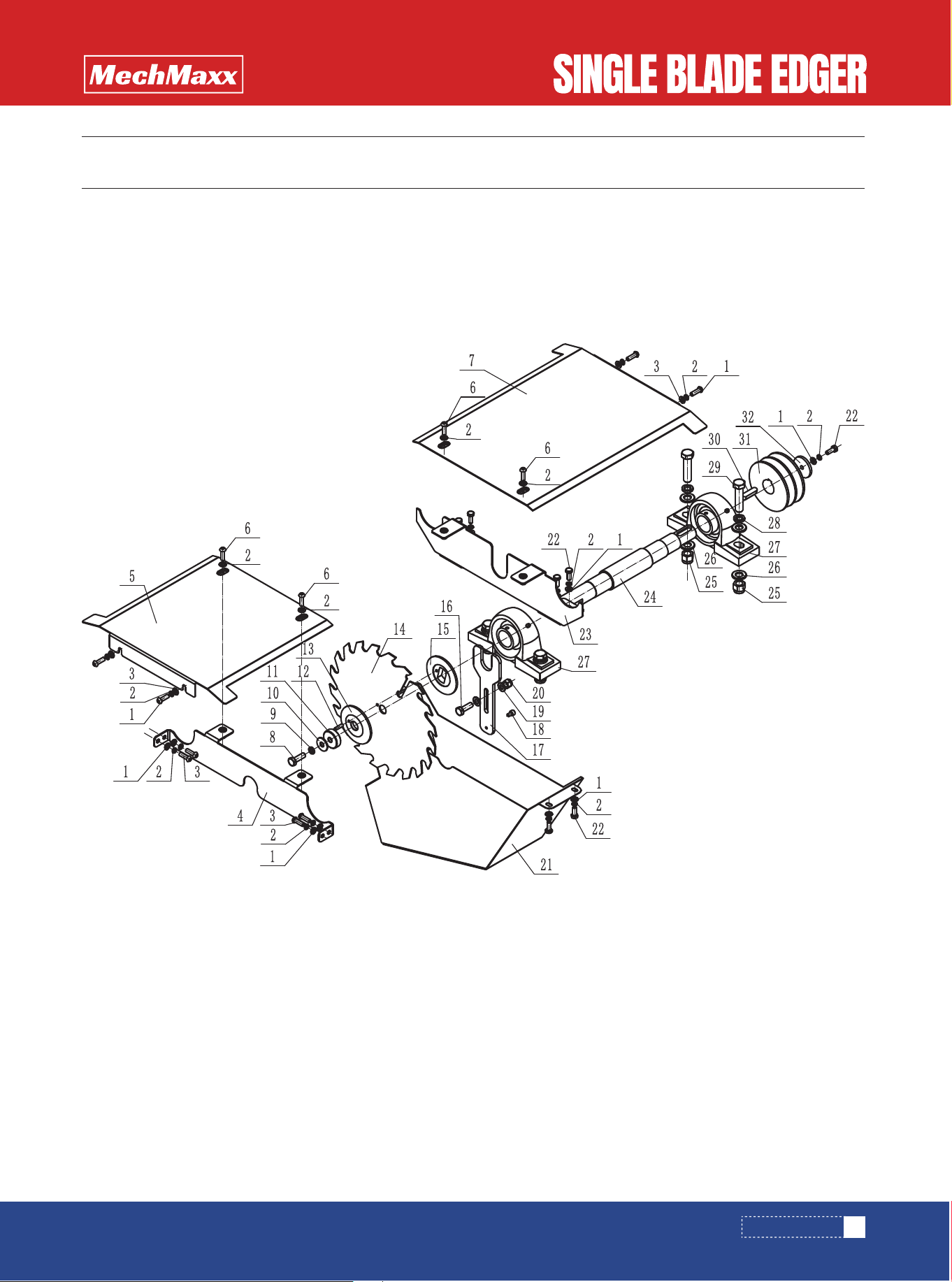
PARTS DIAGRAM
PARTS DIAGRAM

PARTS LIST
22
www.mechmaxx.com
PARTS DIAGRAM
1
2
3
4
5
6
7
8
9
10
11
12
13
14
15
16
17
18
19
20
21
22
23
24
25
26
27
28
29
21
17
8
1
1
4
1
1
1
1
1
1
1
1
1
1
1
1
2
1
1
9
1
1
4
8
2
4
4
1
1
1
30
31
32
Flat washer 6
Elastic washer 6
Hexagon socket head screw M6×20
Support plate 2
Bearing cover 2
Hexagon socket head screw M6×20
Bearing cover 1
Hexagon head bolt M8×25
Elastic washer 8
Large washer 8
Pressure pad
Elastic cylindrical pin straight groove 4×18
Pressing plate 1
Saw blade
Pressing plate 2
Hexagon head bolt M8×25
Removal wrench
Hexagon socket head screw M5×8
Flat washer 8
Self-locking nut M8
Saw cover weldment
Hexagon head bolt full thread M6×16
Support plate 1
Cutter shaft
Hexagon self-locking nut M12
Flat washer 12
Vertical bearing UCP206
Elastic washer 12
Hexagon head bolt full thread M12×45
Flat key 8X7X32
Drive pulley
Gasket
No. Description Qty. No. Description Qty.
23
www.mechmaxx.com
PARTS DIAGRAM
PARTS DIAGRAM
PARTS LIST
1
2
3
4
5
Rear leg weldment
Flat washer 12
Hexagonal bolt M12×70
Hexagonal bolt M12X95
Hexagonal self-locking nut M12
1
8
2
2
4
2
2
2
2
6
7
8
9
Rear leg lock plate
Large side flat washer Φ10*35*3
Hexagonal bolt full thread M10×20
Large side flat washer Φ12*35*3
No. Description Qty. No. Description Qty.
24
www.mechmaxx.com
PARTS DIAGRAM
PARTS DIAGRAM
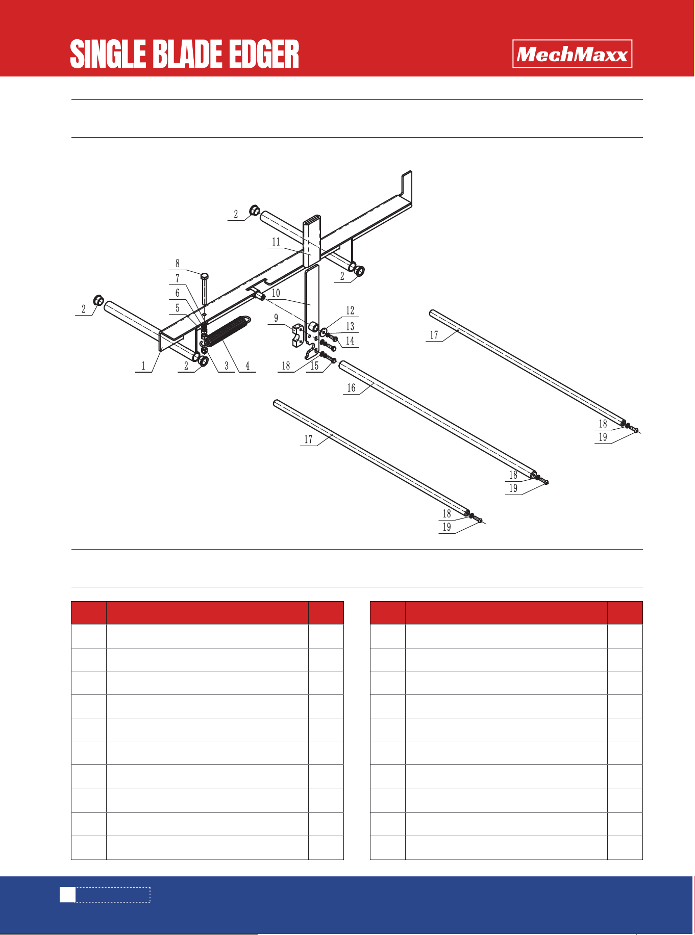
PARTS LIST
1
2
3
4
5
6
7
8
9
10
Front rail weldment
Oil-containing copper sleeve
Hexagonal self-locking nut M8
Tension spring
Hexagonal nut M8
Elastic washer 8
Flat washer 8
Hexagonal head bolt full thread M8×70
Block
Handle weldment
1
4
1
1
2
1
1
1
1
1
1
1
2
1
2
1
2
6
3
11
12
13
14
15
16
17
18
19
Sponge grip
Large edge flat washer Φ6*18*1.2
Elastic washer 6
Hexagonal head bolt full thread M6×16
Hexagonal head bolt full thread M6×20
∅20 optical axis
∅16 optical axis
Flat washer 6
Hexagonal flat round head screw M6×20
No. Description Qty. No. Description Qty.
25
www.mechmaxx.com
PARTS DIAGRAM
PARTS DIAGRAM
PARTS LIST
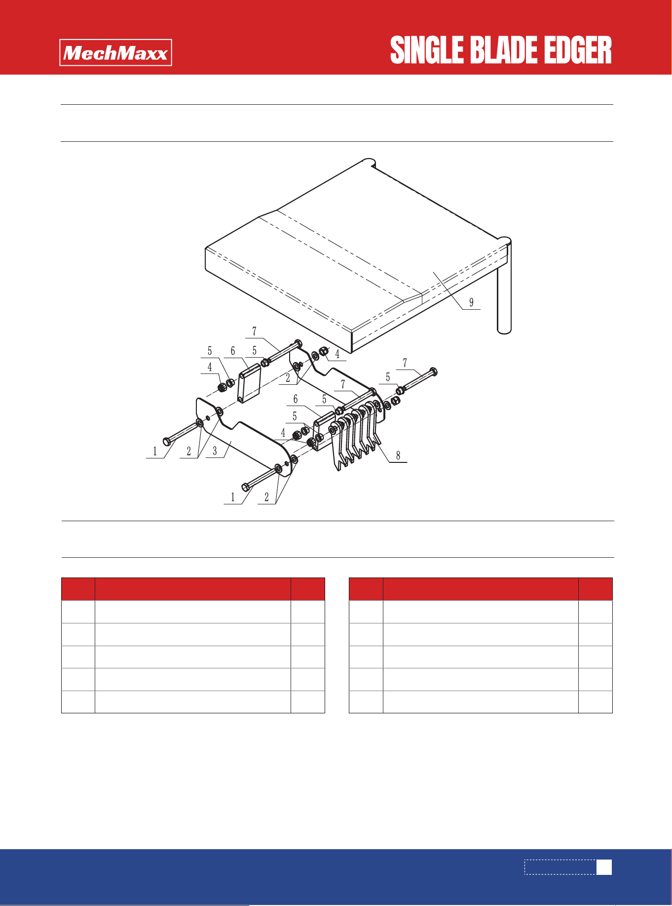
1
2
3
4
5
Hexagonal bolt M10×80
Flat washer 10
Blade guard
Self-locking nut M10
Sleeve 10X16-10
2
15
2
5
6
6
7
8
9
10
Guard connecting plate
Hexagonal bolt M10×90
Check plate
Top guard weldment
2
3
6
1
No. Description Qty. No. Description Qty.
26
www.mechmaxx.com
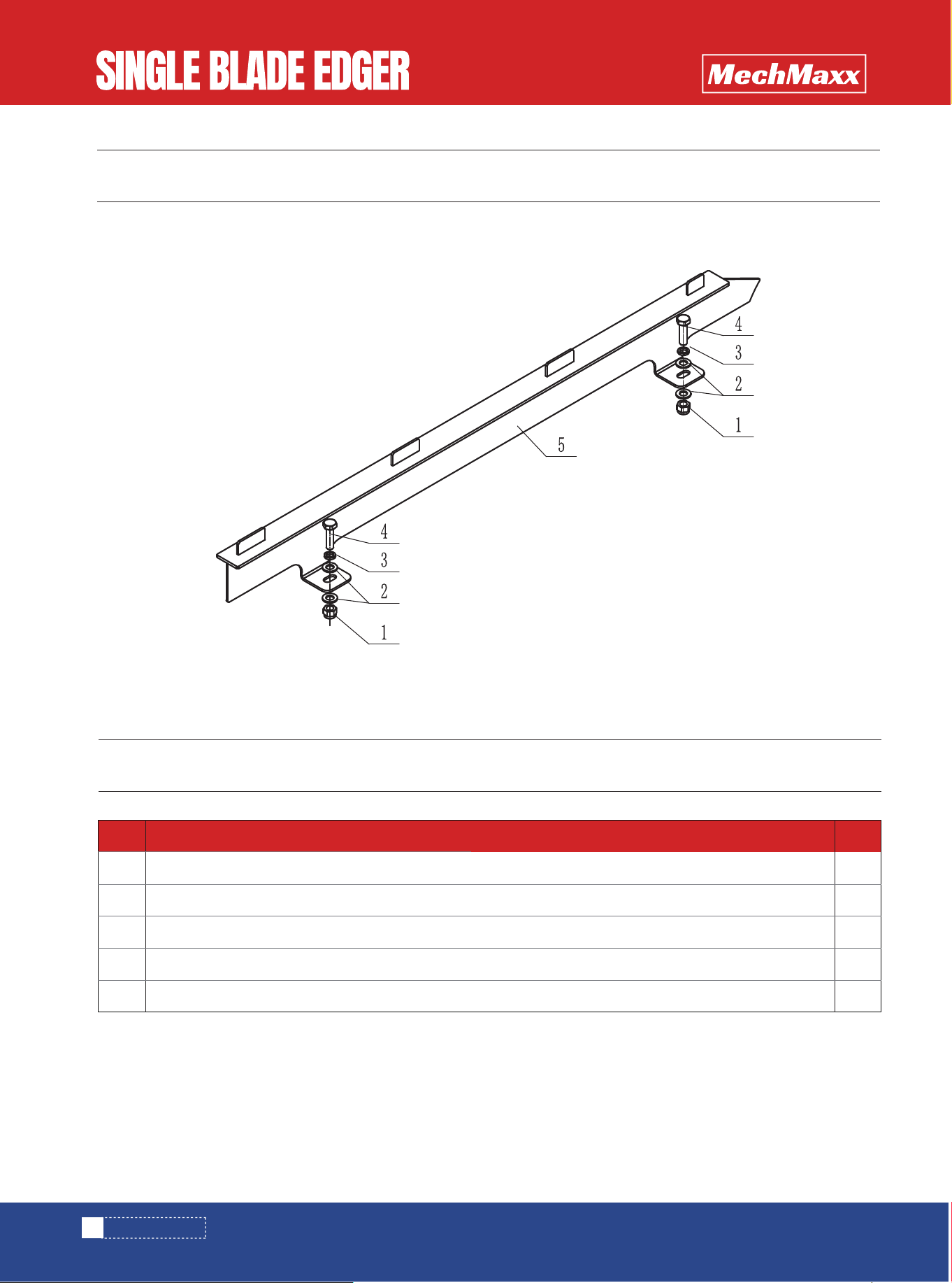
PARTS DIAGRAM
PARTS DIAGRAM
PARTS LIST
1
2
3
4
5
Self-locking nut M10
Flat washer 10
Elastic washer 10
Hexagon head bolt full thread M10×35
Rear guide rail weldment
2
4
2
2
1
No. Description Qty.