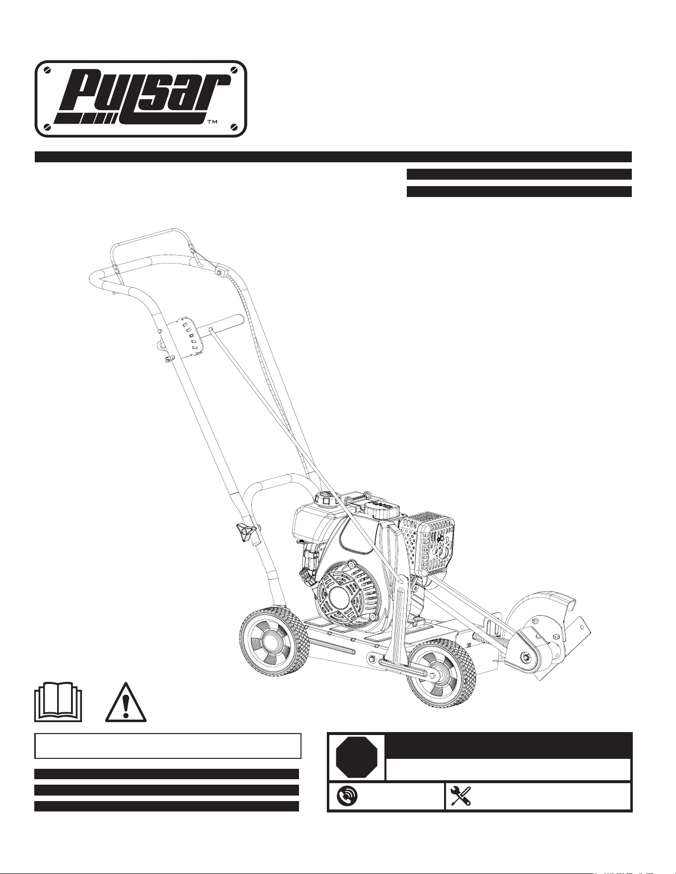
Model# PTG1080
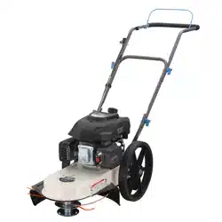
WALK BEHIND EDGER
OPERATOR’S MANUAL
Warning: The Engine Exhaust from this product contains chemicals known to
the State of California to cause cancer, birth defects or other reproductive harm.
support@pulsar-products.com
866-591-8921
STOP
DO NOT RETURN TO STORE!
HAVE QUESTIONS OR NEED SERVICE?
2
Safety Definitions
• Save these instructions
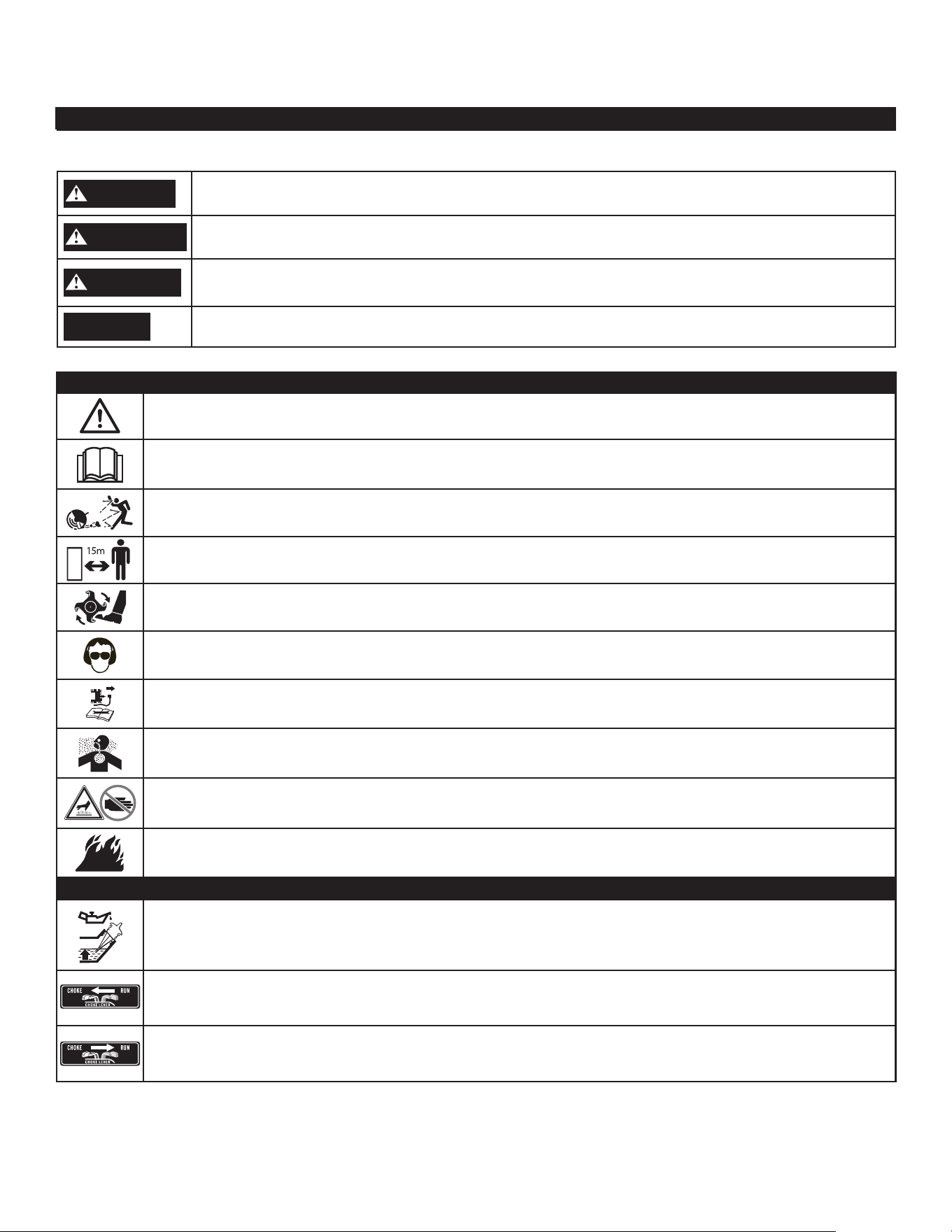
Control and Operating Symbols
The following symbols are used on the product and in this manual to alert the operator of potential safety hazards. Read them
carefully, and understand their meaning.
Safety Alert Symbols
Safety Warning Symbols
The following symbols may be found on your tiller. Carefully read and understand their meaning.
DANGER
Indicates an imminently hazardous situation which, if not avoided, will result in death or serious injury.
WARNING
Indicates a potentially hazardous situation which, if not avoided, could result in death or serious injury.
CAUTION
Indicates a potentially hazardous situation which, if not avoided, may result in minor/moderate injury.
NOTICE
Indicates a practice not related to personal injury which, if not avoided, may result in property damage.
Look for this symbol to point out important safety precautions. It means: Attention! Become Alert!
Your Safety Is Involved.
Read operator’s manual before operating this machine. Failure to follow directions could result in
serious injury.
Thrown objects. Remove all rocks, stones, and foreign objects which could be thrown by machine.
Do not
use if children or bystanders are present.
Rotating tines can cause serious injury. Keep hands, feet, and clothing away.
Wear eye protection complying with ANSI Z87.1 and hearing protection.
Disconnect spark plug wire when not in use or before servicing, cleaning, or performing maintenance on the unit.
Engine exhaust contains carbon monoxide, an odorless and deadly gas. NEVER run unit indoors or in a poorly
ventilated area.
DO NOT touch hot muffler or cylinder. These parts are extremely hot from operation and may remain hot for a
short time after operation.
To reduce risk of fire, clean spilled gas and oil and keep unit free from debris. Gasoline is extremely flammable.
Allow machine to cool before refueling.
Oil Fill Location: Do Not Overfill
Choke/Cold Start
Run/Warm Start

3
Control and Operating Symbols (Continued)
Responsibility of Operator
1. Carefully read and follow these safety instructions. Failure to do so can result in serious injury.
2.
Know your product. Read and understand this manual before use. Compare the illustrations to unit. Learn location
and function of all controls. Thoroughly understanding the unit before use will result in the best performance and safety.
3. Follow all instructions when assembling the unit. If the unit was purchased in assembled condition, the operator must
check the unit carefully to make sure it was assembled according the instructions in the manual before use.
4. Regularly inspect the edger. Make sure parts are not bent, damaged, or loose.
5. Use this equipment for its intended purpose only.
6. Operate the unit only with guards, shields, and other safety items in place and working correctly.
7. Service the unit only with authorized or approved replacement parts.
8. Complete all unit maintenance and adjustments according to the instruction in this manual.
WARNING
Engine Exhaust, some of its constituents, and certain vehicle components contain or emit chemicals known to the State
of California to cause cancer and birth defects or other reproductive harm.
To prevent accidental starting when setting up, transporting, adjusting or making repairs, always disconnect spark plug
wire and put wire where it cannot contact the spark plug.
Preparation Safety
WARNING
• Read, understand, and follow all instructions on the machine and in this manual. Be thoroughly familiar with the
controls and the proper use of the edger before starting. Know how to stop the engine quickly.
• Familiarize yourself with all the safety and operating decals on this equipment.
• Thoroughly inspect the area where the edger is to be used and remove all foreign objects. Your equipment can propel
small objects at high speed causing personal injury or property damage. Stay away from breakable objects, such as
house windows, auto glass, greenhouses, etc.
• Check that all nuts and bolts are tight and equipment is in good condition.
• Always check that the ground wire is connected before starting engine.
Important Safety Information
• Save all instructions
Safety Definitions (Continued)
• Save these instructions
Depth Control Lever: Move lever forward to increase cutting depth
Start Position
Start Lever:
Release lever to stop engine. Engage lever to start/run engine

4
Important Safety Information (Continued)
• Save all instructions
Operation Safety
• Never allow children or young teenagers to operate the edger.
WARNING
• Keep area of operation clear of all bystanders, particularly small children and pets.
• Only allow responsible individuals, who are familiar with the instructions, to operate the edger.
•
or affect your ability to operate this machine safely.
• Do not use this machine if you are mentally or physically unable to operate the machine safely.
• Always wear ANSI compliant safety goggles or safety glasses with side shields when operating edger to protect your
eyes from foreign objects, which can be thrown from the unit.
• Wear appropriate clothing such as a long sleeved shirt or jacket. Also wear long trousers or slacks. Do NOT wear
shorts. Do NOT wear loose clothing, which could get caught in this equipment.
• Always wear work gloves and sturdy footwear such as leather work shoes or short boots. These will protect ankles and
, and improve traction.
• It is advisabl
low hanging branches, twigs, or other objects, which may be unnoticed by the operator.
WARNING
• Do not put hands or feet near or under rotating parts.
• Exercise extreme caution when operating on or crossing gravel drives, walks, or roads. Stay alert for hidden hazards
• Exercise cau
never run. Never operate the edger at high transport speeds on slippery surfaces.
• Look behind and use care when backing.
• Never operate the edger without good visibility or light.
DANGER
• Do not run the engine indoors or inside a closed area. The exhaust fumes are dangerous, containing CARBON
MONOXIDE, an ODORLESS AND DEADLY GAS.
• Never leave the edger unattended when the engine is running. Stop the engine and make sure all moving parts have
stopped. Remove the wire from the spark plug.
• Do not overload the edger capacity by attempting to till too deep at too fast a rate.
• If the edger should start to vibrate abnormally, stop the engine, disconnect the spark plug wire and prevent it from
touching the spark plug. Check immediately for the cause. Vibration is generally a warning of trouble.
• Watch for holes, ruts, bumps, or other rough ground. Tall grass can hide obstacles.
Fuel Safety
WARNING
• Gasoline is e
• Use an approved container.
• Check fuel supply before each use, allowing space for expansion as the heat of the engine and/or sun can cause fuel
to expand.
• Fill fuel tank
• Never remove gas cap or add fuel with the engine running. Allow engine to cool before refueling.
• Do not smoke while refueling.
• After refueling, replace fuel tank cap securely and wipe up spilled fuel.
• Never store fuel or edger with fuel in the tank inside a bu

5
Important Safety Information (Continued)
• Save all instructions
Storage Safety
•
Always refer to the operator’s manual instructions for important details if the edger is to be stored for an extended period.
• Never store the edger with fuel in the fuel tank inside a building where ignition sources are present such as water
heaters, space heaters, clothes dryers, etc.
•
• Allow the engine to cool before storing in any enclosure.
Repair, Maintenance, and Adjustment Safety
• After striking a foreign object, stop the engine. Remove the wire from the spark plug and keep the wire away from the
plug to prevent accidental starting. Thoroughly inspect the edger for any damage. If damaged, have the
equipment repaired by a trained technician before restarting and operating.
WARNING
• Stop the engine before cleaning, repairing, or inspecting the unit. Make sure all moving parts have stopped. Let the
engine cool, disconnect the spark plug wire and move it away from the spark plug.
•
by the manufacturer.
• Keep the edger in safe working condition. Check all fasteners at frequent intervals for proper tightness.
• When servic
Manual. Service and repair procedures can be done with the edger in an upright position. Some procedures will be
easier if the machine is lifted on a raised platform or working surface.
• Use only original equipment or authorized replacement parts.
• Never tamper with safety devices. Check their proper operation regularly.
• Do not change the engine governor setting or over-speed engine.
• Clean and replace safety and instruction decals as necessary.
• T
Children Safety
WARNING
• Tragic accidents can occur if the operator is not alert to the presence of children. Children are often attracted to the
edger and the edging activity.
• Keep children out of the edging area and under the watchful care of a responsible adult.
• Never assume that children will remain where you last saw them.
• Be alert and turn edger off if children enter the area.
• Before and while moving backwards, look behind and down for small children.
• Never allow children to operate the edger.
• Use extra care when operating near blind corners, shrubs, trees, or other objects that may obstruct vision.
6
Edger Specications
• Save all instructions
Unit Weight. . . . . . . . . . . . . . . . . . . . . . . . . . . . 47 lbs.
1”-2.3”
Cutting Depths . . . . . . . . . . . . . . . . . . . . . .
Blade Diameter. . . . . . . . . . . . . . . . . . . . . . . . . . 9”, 2 Point
Gasoline Type ..... Regular Unleaded / 92 Octane (min.)
Gasoline Capacity . . . . . . . . . . . . . . . . . . . . Oil
Type (API SG-SL) . . . . . . . . SAE10W-30 is recommended
for all service temperatures .
Spark Plug Model. . . . . . . . . . . . . . . . . . . . . . . . . . . F6RTC
Spark Plug Gap . . . . . . . . . . . 0.024-0.028 in. (0.6-0.7 mm)
Engine Type . . . . . . . . . . . . . . . . . . . . . . . . . 4 Stroke OHV
Displacement
. . . . . . . . . . . . . . . . . . . . . . . . . . . . . . . .151cc
RPM
. . . . . . . . . . . . . . . . . . . . . . . . . . . . . . 3000 RPM
See page 7 for additional information.
Oil Capacity . . . . . . . . . . . . . . . . . . . . . . . . . . . . (400 ml)
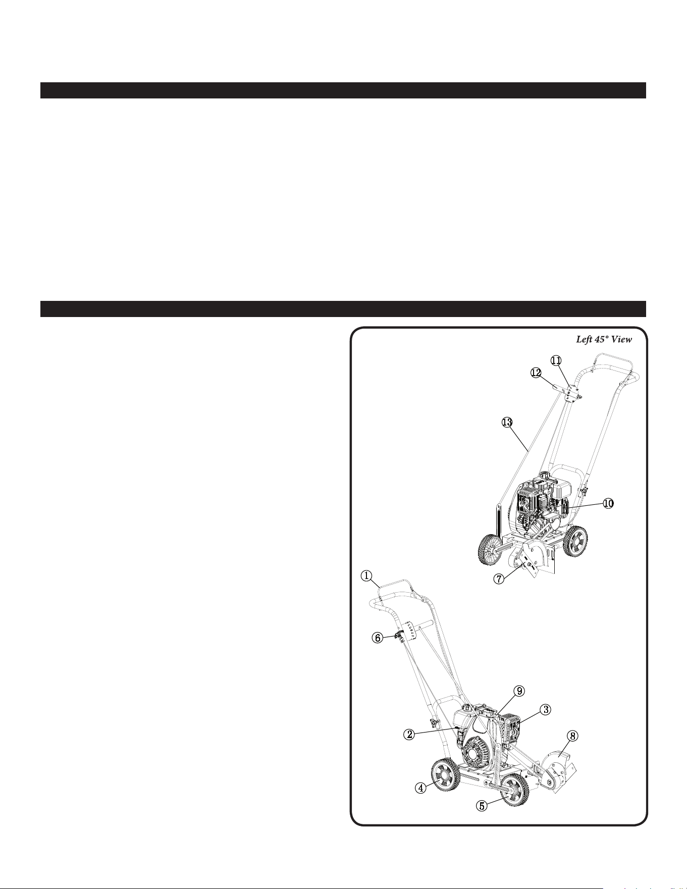
Parts & Features
1. Start Lever - Lever on handle which allows the engine to
run. When lever is released, engine will stop.
2. Choke Control - Restricts the air intake. This allows
for an enriched fuel-air mixture which helps to start
the engine.
3. Muer - Location of engine exhaust.
4.
5.
6.
Adjustable Rear Wheel -
Right rear wheel is adjustable to
level the edger when edging along a curb (curb-hopping).
Adjustable Front Wheel - The front wheel can adjust
down for curb-hopping.
Recoil Starter Handle - The engine is equipped with an
easy pull recoil starter.
7.Blade - Rotating cutting element
.
8. Blade Guard - Prevents stones and debris from being
thrown at the operator.
9. Spark Plug/Spark Plug Wire -
Provides spark to ignite air/
fuel mixture. The Spark Plug Wire must be disconnected
and moved away from the Spark Plug when servicing
the unit.
10. Air Filter - Removes debris and contaminates from
intake air, allowing engine to run smoothly with
low exhaust.
11. Depth Selector Plate
12. Depth Control Lever
13. Control Rod - Used to control the edging depth of cut.
Right 45° View
Figure 1
1.2L
7
Read and follow the assembly instructions. Do not discard
any parts or materials until the unit is assembled.
References to the right or left side of the edger are from
the viewpoint of the operator’s position behind the edger.
WARNING
Do not operate edger if it is damaged or not completely
and correctly assembled. Before doing any assembly or
maintenance to the unit, remove the wire from the spark
plug. Always wear ANSI compliant safety glasses with side
shields while assembling the edger.
Assembly
• Save all instructions
1. Remove all parts and packaging components.
2. Use a utility knife to cut all 4 vertical edges and lay the
side panels flat around the edger.
How to Remove Edger from Carton
A
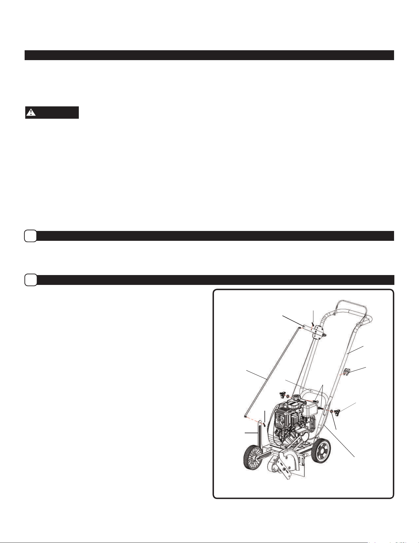
NOTE: Refer to Figure 2 when following steps below:
1. Assemble the upper handle to the lower handle with the
(2) pipe bolts and the (2) plastic wing nuts. Firmly
hand tighten the wing nuts.
2. Slide one end of the control rod into the hole of the
Depth Control Lever. Secure with hairpin.
3. Slide the other end of the control rod through the hole of
the quill arm. Secure with second hairpin.
4. Attach the recoil starter handle through the rope guide,
by twisting it into position.
How to Assemble the Handle
B
Upper
Handle
Lower
Handle
Hair Pin
Control Rod
Quill Support
Arm
Hair Pin
Pipe
Bolt
Figure 2
Depth Control
Lever
Plastic
Wing Nut
Handle
Ground
Wire
Engine flameout
control line
The following components will be found in the carton.
Quantities shown in ( ).
1. (1) Edger
2. (1) Edger Operator’s Manual
3. (1) Upper Handle
4. (1) Control Rod
5. (1) Parts bag containing the following:
(2) Hair Pins
(2) Plastic Wing Nuts
(M8)
(2) M8x45mm Pipe Bolts
(2) Wire Tie
(2) Flat washer
(1) Clip
(1) Spark plug sleeve
NOTE: Depending on the model, the fasteners to attach the
wheels will either be loosely assembled to the unit or in a
separate plastic bag. See assembly instructions.
3. Remove any remaining packaging.
4. Roll the unit out from the carton, and place on a hard
level surface.
Flat washer
8
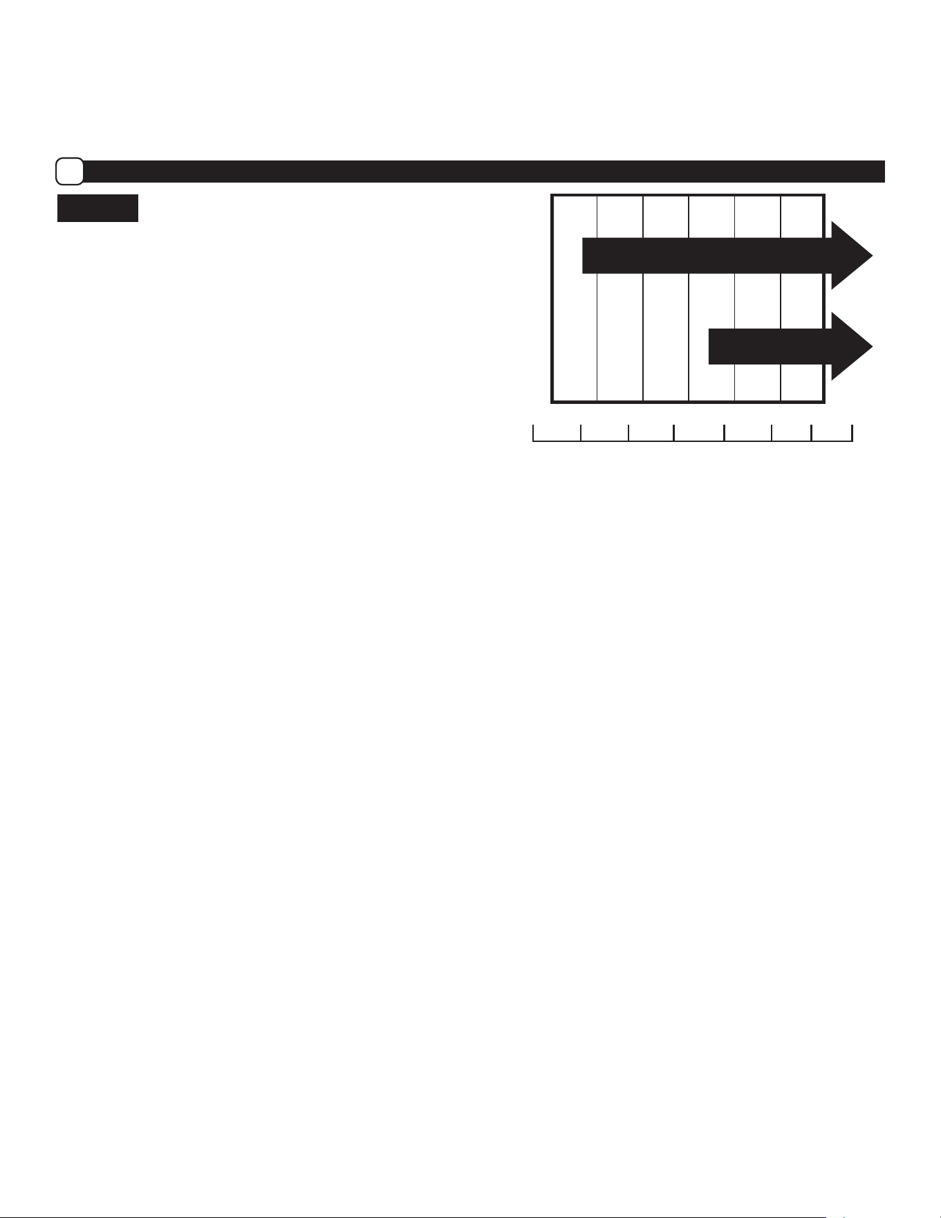
Engine Preparation
• Save all instructions
SAE
TEMP
100° F
40° C
-20
01-03- 02-
0
0
20
01 02
40
60 80
30
Ambient Service Temperature
SAE 10W-30
SAE 30
A
Engine Oil
NOTICE
Engine shipped without oil. Failure to add oil will result in
serious engine damage.
Refer to the chart on the right for alternative oil types to
use at different temperatures. Always use a high quality
detergent oil classified “For Service, SG, SH, SJ” or
higher. Do not use special additives.
Always use recommended oil type. Using dirty oil or
incorrect oil type such as 2-stroke engine oil will shorten
engine life.
NOTE: Engine Oil Capacity is 400 ml .
9
WARNING
Before checking oil, make sure engine is off, and spark
plug wire has been disconnected from spark plug.
3. When oil level is full, the oil will be at upper limit on dip
stick. If oil level is near or below the lower limit, oil must
be added. (See Figure 4)
4. Add oil slowly until the oil level reaches the upper limit of
the dipstick. Use a funnel or nozzle to reduce spillage.
NOTICE
Frequently check oil level while filling. DO NOT OVERFILL.
DO NOT UNDERFILL. Running engine at improper oil level
will seriously damage engine.
6. Replace and tighten dipstick.
7. Clean up any spilled oil.
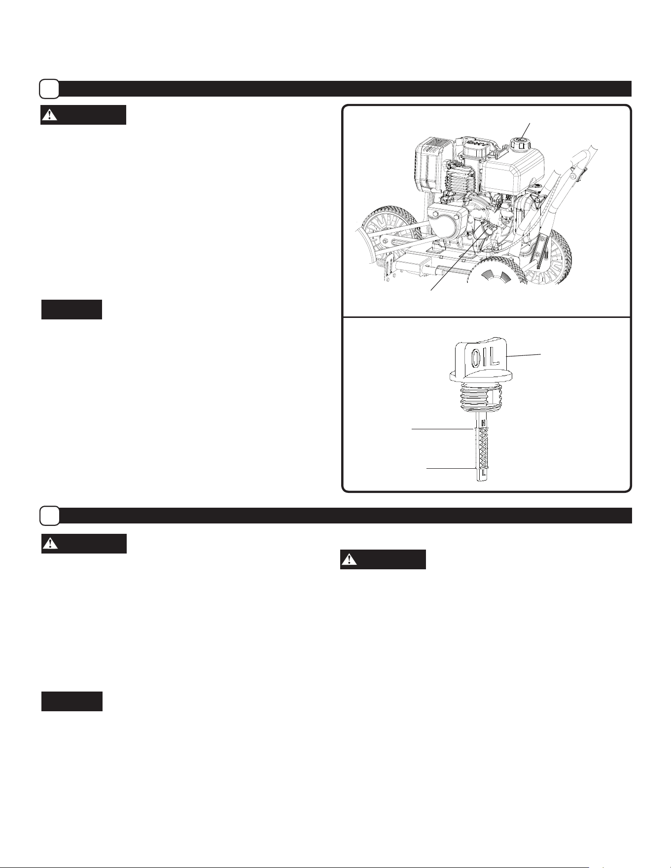
Oil Fill Cap/Dipstick
Fuel Tank Cap
Oil Fill Cap/
Dipstick
Upper Limit
Lower Limit
Figure 3
Figure 4
Engine Preparation (Continued)
• Save all instructions
Fuel
C
How to check oil level and ll to proper level
B
WARNING
Gasoline is extremely flammable and vapors can
explode if ignited. Handle with care.
Use fresh unleaded gasoline with an octane rating of 87
or higher. Do not use gasoline containing more than
10% ethanol. Use of non-ethanol fuel is best. We
recommend the continuous use of a fuel additive /
stabilizer to counteract the effects of ethanol. These
additives also prolong the shelf life of gasoline.
NOTICE
Using incorrect fuel type or contaminated fuel will cause
serious engine damage.
NOTE: Fuel tank capacity is approximately 1.2L
How to Fill Engine with Fuel
WARNING
Turn engine off and let engine cool for several minutes
before removing the fuel cap or adding fuel. Never fill fuel
tank indoors. Do not smoke while adding fuel.
1. Clean surface around fuel tank cap to prevent
contamination. (See Figure 3)
2. Loosen fuel cap slowly. After removing cap, place on a
clean surface.
3. Pour fuel into the tank. Use care to avoid spillage.
NOTE: DO NOT overfill fuel. Allow space for the fuel to
expand due to heat from engine and/or sun.
4. Before replacing the fuel cap, inspect and clean the fuel
cap seal.
5. Replace the fuel cap and securely hand-tighten.
6. Clean up any spilled fuel.
1.Remove the oil fill cap/dipstick and wipe clean with cloth.
(See Figure 3)
2. Insert dipstick into fill spout but do NOT screw in.
Remove dipstick and check oil level.
10
Operation
• Save all instructions
Before Starting the Engine
A
WARNING
Before starting engine, read operator’s manual. Become
familiar with location and function of all controls. Know
how to stop the engine quickly.
WARNING
Before starting the engine, check that the ground wire
terminals have been connected.
Before attempting to start the engine, review the
following steps:
1. Unit has been assembled according to all
assembly instructions.
2. Ground wire terminals are connected.
3. Unit has been inspected for any damaged or
missing components.
4. No parts are remaining in the carton.
5. Engine oil is at proper level.
6. Fresh, clean, regular-unleaded gasoline has been
added to fuel tank.
7. Spark plug wire is connected to spark plug.
8. Edger has been moved to desired location.
9. Edger is on level surface.
WARNING
Keep all bystanders, especially CHILDREN, away during
operation.
How to Start Engine
B
DANGER
Never Run engine indoors or in a poorly ventilated
area. Engine exhaust contains Carbon Monoxide, an
ODORLESS and DEADLY gas.
WARNING
Debris thrown from edger can cause severe eye damage.
Always wear ANSI compliant safety glasses or eye
shields when operating edger. If you wear eyeglasses,
put an OSHA certified Wide-Vision Safety Mask over
your eyeglasses.
1. Review ALL steps in the “BEFORE STARTING THE
ENGINE” section.
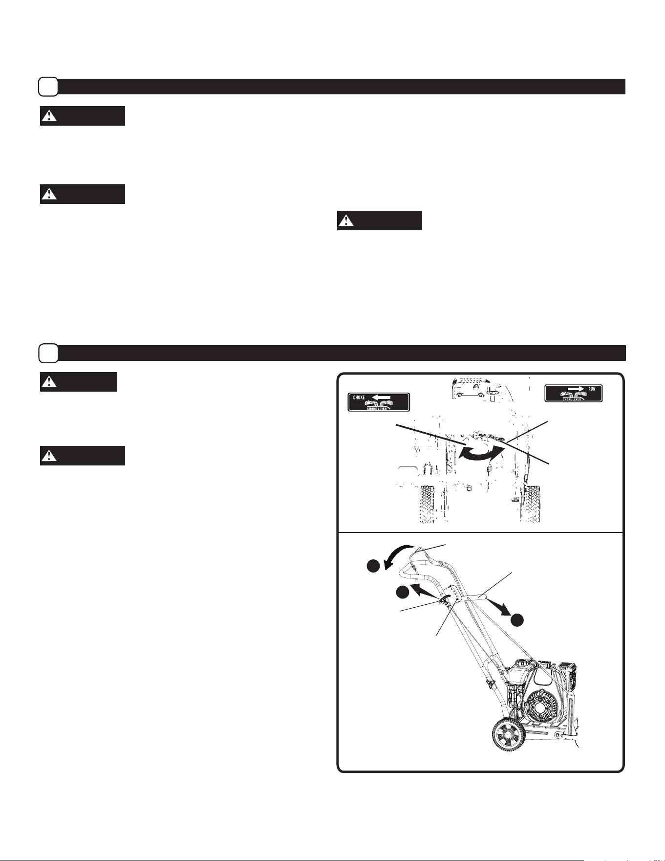
2. Move the Depth Control Lever to the Start Position.
(See Figure 6-①)
3. Rotate Choke to the Choke Position. (See Figure 5)
NOTE: Not required when re-starting a warm engine.
4. Firmly grip the edger handle with your left hand , Pulling
the Start Lever against the handle (See Figure 6-②).
NOTE: Engine will not start if the Start Lever is not
pulled against the handle.
5. Firmly grip the Recoil Starter Handle with your right hand.
(See Figure 6-③)
6. Pull the recoil slowly, until you feel tension in the starter
rope. Then quickly pull the recoil starter handle to
completely unwind the starter rope. DO NOT allow the
starter rope to snap back. Let the starter rope
slowly
rewind.
Lever
Depth
2
Control
Lever
3
Recoil
1
Starter
Handle
Start
Position
RUN /
Warm Start
CHOKE /
Cold Start
Start
Figure 5
Figure 6
Control level
IMPORTANT: This unit’s engine exhaust system is equipped
with a spark-arresting muffler. Tampering with or removing
the spark-arrestor violates section 4442 of the California
Public Resources Code as well as other applicable state
and federal law.
11
Operation (Continued)
• Save all instructions
How to Stop the Edger
C
Release the start lever (See Figure 6). This will ground
out the engine through the ground wire, causing the
engine to stop.
How to Change the Edger Cutting Depth
D
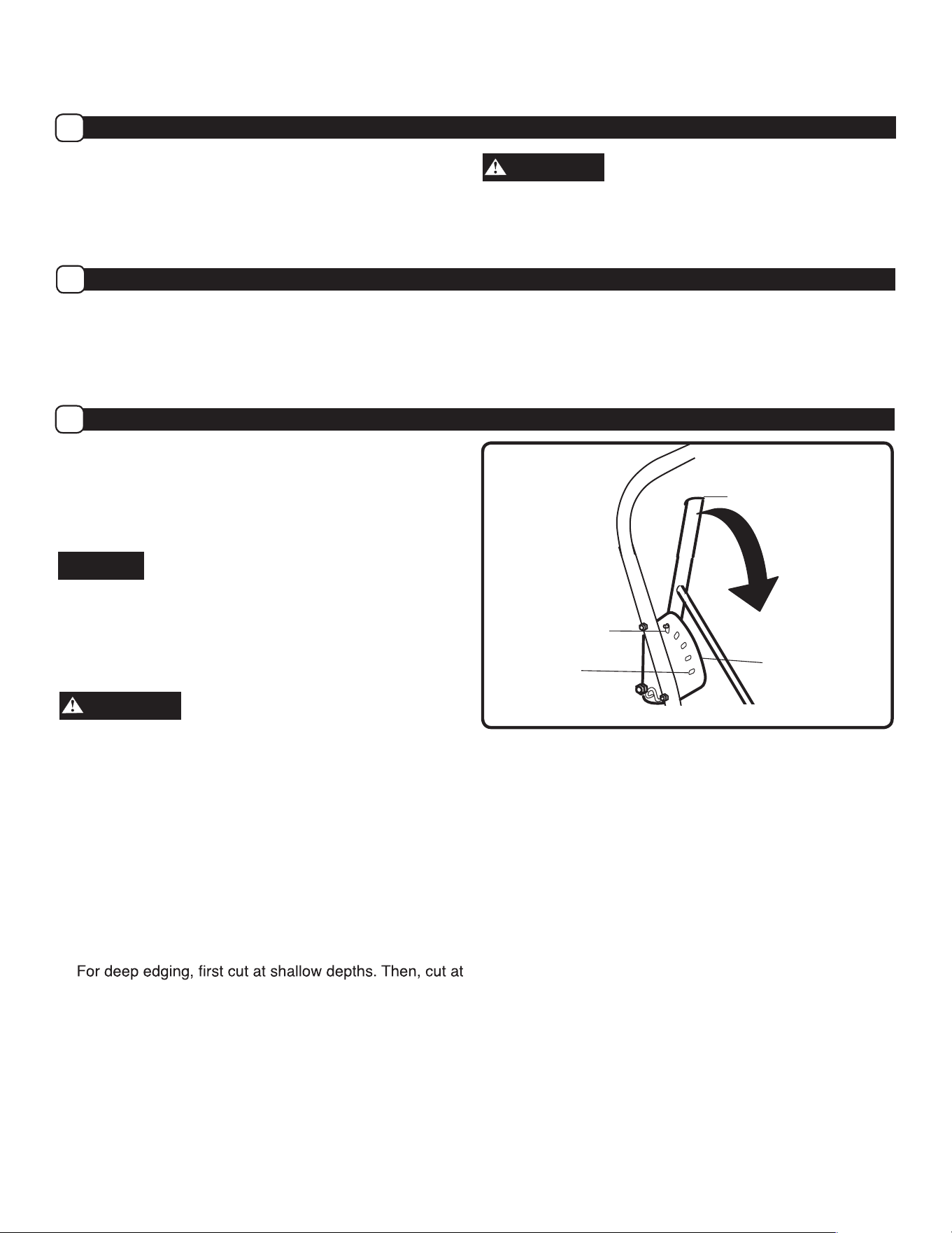
Move the Depth Control Lever forward to increase the
depth. (See Figure 7)
NOTE: There are 5 cutting depth settings from
approximately ground level to 60 mm deep.
NOTICE
Do not overload the edger capacity by attempting to edge
too deep at too fast a rate. To edge at deeper settings,
make multiple passes, first cutting at shallow depths.
Depth Control
Lever
Full Depth
Start Position
Forward
Depth Selector
Plate
Figure 7
7. After the engine starts, wait 2-5 seconds and rotate the
choke back to the RUN position.
8. If engine fails to start after 5 or 6 more attempts, see
instructions in the “Troubleshooting Chart”.
How to Start Engine (Continued)
B
WARNING
Keep hands, feet, hair, and loose clothing away from any
moving parts. Avoid touching muffler and surrounding areas
temperatures can exceed 150 degrees. Keep all safety
devices and shields in place.
Edging Tips
WARNING
Read the Operator’s manual. Know location and functions
of all controls. Keep all safety devices and shields in place.
Never allow children or uninstructed adults to operate the
edger. Keep bystanders away from machine. Keep away
from the blade and all rotating parts, which cause injury.
• Edging is best performed when conditions are dry. If the
soil is too wet, dirt becomes packed around the blade
causing premature belt wear and decreased performance.
• If dirt does become packed around the blade, stop the
engine and remove the wire from the spark plug.
Remove the packed dirt and debris from the blade.
•
greater depths until the desired depth is obtained.
• Edging can be customized by varying the number of
passes and the distance between the blade and the edge
of sidewalk, driveway, or curb.
HIGH ALTITUDE OPERATION
If operating equipment with engines regularly at
altitudes over
5,000 feet, the carburetor’s air-fuel
mixture will be too rich and emmissions may increase.
On engines not built for the United States the
carburetor can be adjusted to operate under this
condition. The carburetor should be returned to its
normal setting if regular operation is less than 5,000
feet. Contact your service center to modify the
carburetor.
•

12
Maintenance
• Save all instructions
Maintenance Schedule
A
WARNING
Before performing any maintenance, turn engine off and remove the wire from the spark plug to prevent accidental
starting and serious injury.
IMPORTANT: The warranty on this edger does not cover items that have been subjected to operator abuse or negligence. To
receive full value from the warranty, the operator must maintain the edger as instructed in this manual, and only use genuine
replacement parts. The following table lists required periodic maintenance.
CAUTION
IMPORTANT (Notes about Maintenance schedule)
1. Re-check tightness of all fasteners after first 2 hours of initial use.
2. Change engine oil after first 5-8 hours of initial use.
3. Change oil every 25 hours if operating under heavy load or in high temperatures.
4. Clean air filter every 10 hours if operating under dusty conditions.
WARNING
Use only GENUINE replacement parts. Other parts may damage the unit or result in injury.
PERIODIC MAINTENANCE SCHEDULE TABLE
Service Records-
Fill in dates as you complete regular
service
Before
Each Use
After
Every
10 Hours
of Use
After
Every
25 Hours
of Use
After Every
50 Hours of
Use
After
Every
100 Hour
of Use
Before
Each
Season
Before
Storage
See
Note
Below
Check Engine Oil Level,
Fill to Proper Level
√ √
Clean Debris From Unit √ √ √
Lubricate All Pivot Points √ √ √
Check Fasteners for Tightness √ √
Check Drive Belt
Replace if Necessary
√ √
Check Blade for Wear or Damage
Replace if Necessary
√ √
Check Fuel Line
Replace if Necessary
√ √
Lubricate Wheel Axles √ √ √
Check Spark Plug
Replace if Necessary
√ √
Change Engine Oil √ √ √
Clean Air Filter
Replace if Necessary
√ √
Replace Spark Plug √
Clean Combustion Deposits from
Cylinder, Piston, and Valves
√
Maintenance (Continued)
• Save all instructions
Lubrication
B
Add a small amount of engine oil to lubricate parts and
pivot points. Refer to “Periodic Maintenance Schedule
Table” for time intervals to lubricate parts.
How to Change the Engine Oil
C
NOTE: Refer to Figure 10 when following the steps below:
1. Stop the engine and let it cool.
2. Disconnect spark plug wire from the spark plug.
3. Raise the front of the unit, by lowering the height of the
front wheel. Refer to How to Edge Along a Curb.
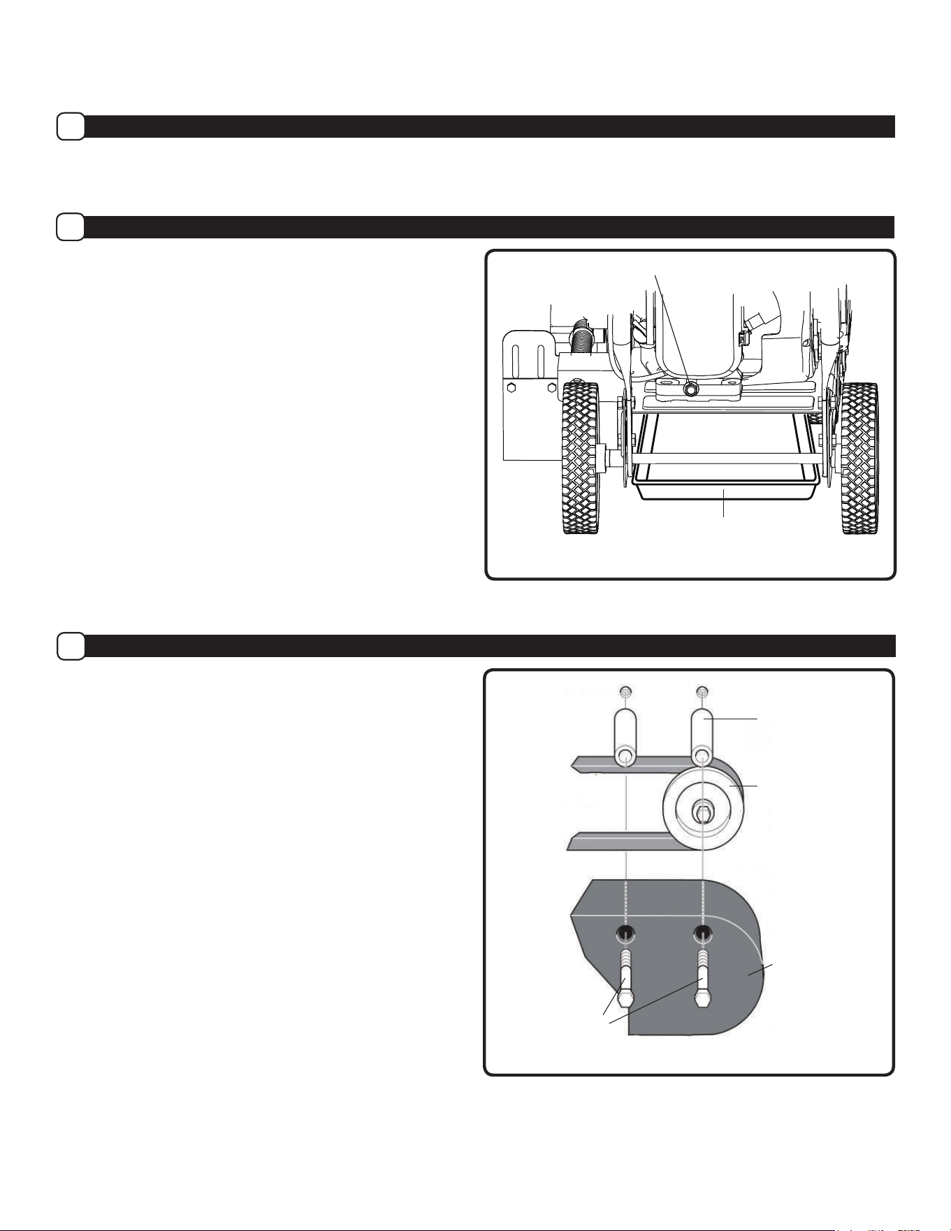
4. Insert a flat pan under the edger, underneath the oil
drain plug and frame hole.
5. Remove oil dipstick. (See Figure 3)
6. Remove the oil drain bolt and washer.
7. Allow all oil to drain through the frame hole into the pan.
IMPORTANT: Used oil is a hazardous waste. Place oil in a
sealed container and take to your local recycling center. Do
NOT discard with household waste.
8. Replace and tighten the oil drain plug and washer.
9. To re-fill engine with oil, see engine preparation section
How to Check Oil and Fill to Proper Level.
How to Replace the Belt
D
IMPORTANT: Only use a replacement belt from the manufacturer.
To order spare parts call us at 866-591-8921.
1. Disconnect the spark plug wire from the spark plug.
2. To ease the replacement of a belt, remove the control rod
(See Figure 2). This will allow the quill arm to rotate back
creating slack in the belt.
3. Remove the two rear guard bolts to remove the engine
pulley cover. (See Figure 11)
Drain Plug and Washer
Spacer
Engine Pulley
Engine Pulley
Cover
Rear Guard
Bolts
Figure 10
Figure 11
Pan
13
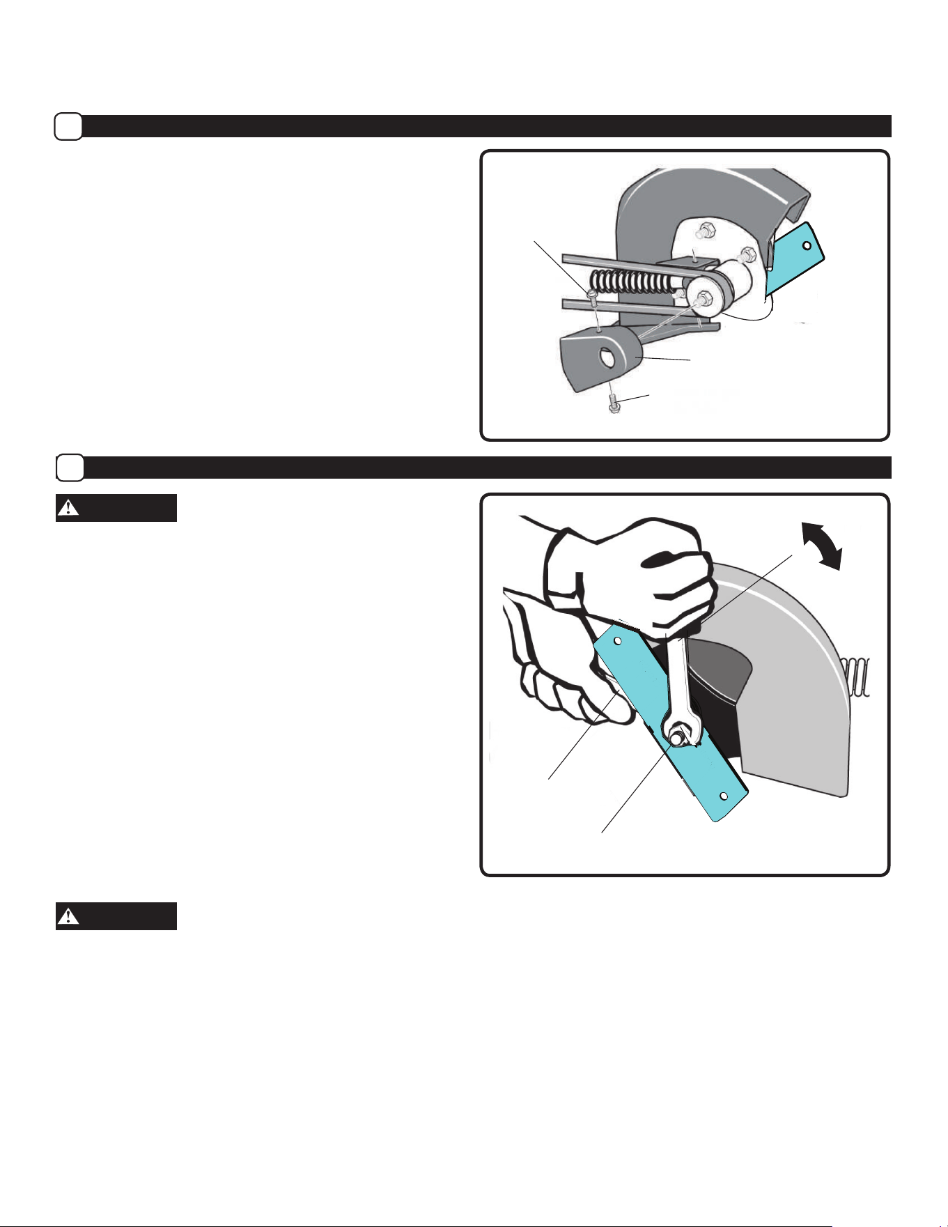
How to Change the Blade
F
WARNING
Do not sharpen the blade. Sharpening can damage the
blade and cause it to break, which can cause injury to you
or to others.
The blade is subject to nicks, scratches, and dents, which
will generally not affect function. The blade is also subject
to wear – reducing the cutting depth. Replace a worn blade
by following the steps below:
IMPORTANT: Only use a replacement blade from the
manufacturer. To order spare parts call us at 866-591-8921.
NOTE: Replacing the blade requires two (2) 12” adjustable
wrenches, or two (2) 3/4 in. [19mm] wrenches.
1. Shut off engine.
2. Disconnect the spark plug wire from the spark plug.
3. Remove the blade locknut that holds the blade to the
drive shaft. (See Figure 13)
WARNING
To remove or tighten the blade locknut, always use the
method shown in Figure 13. Always position the holding
wrench on the nut behind the blade.
4. Remove the blade.
5. Replace with new blade from the manufacturer by
reversing the above steps.
NOTE:
Tighten the blade locknut to 35-45 foot-pounds
(47-61 N-m).
4. Remove the two Front Guard Screws and the Belt Guard.
(See Figure 12)
5. Remove the old belt from the engine and quill
assembly pulleys.
6. To install a replacement belt from the manufacturer,
reverse the steps above.
NOTE: The rear guard bolts should be tightened to 13-16
foot-pounds [18-22N-m].
NOTE: The front guard screws should be tightened to 4-6
foot-pounds [6-8N-m].
How to Replace the Belt (Continued)
E
Maintenance (Continued)
• Save all instructions
Front Guard
Screws
Belt Guard
Front Guard
Screws
Figure 12
Hold Nut,
Do Not Turn
Turn counter-clockwise
to loosen
Figure 13
Turn clockwise
to tighten
Blade Locknut
14
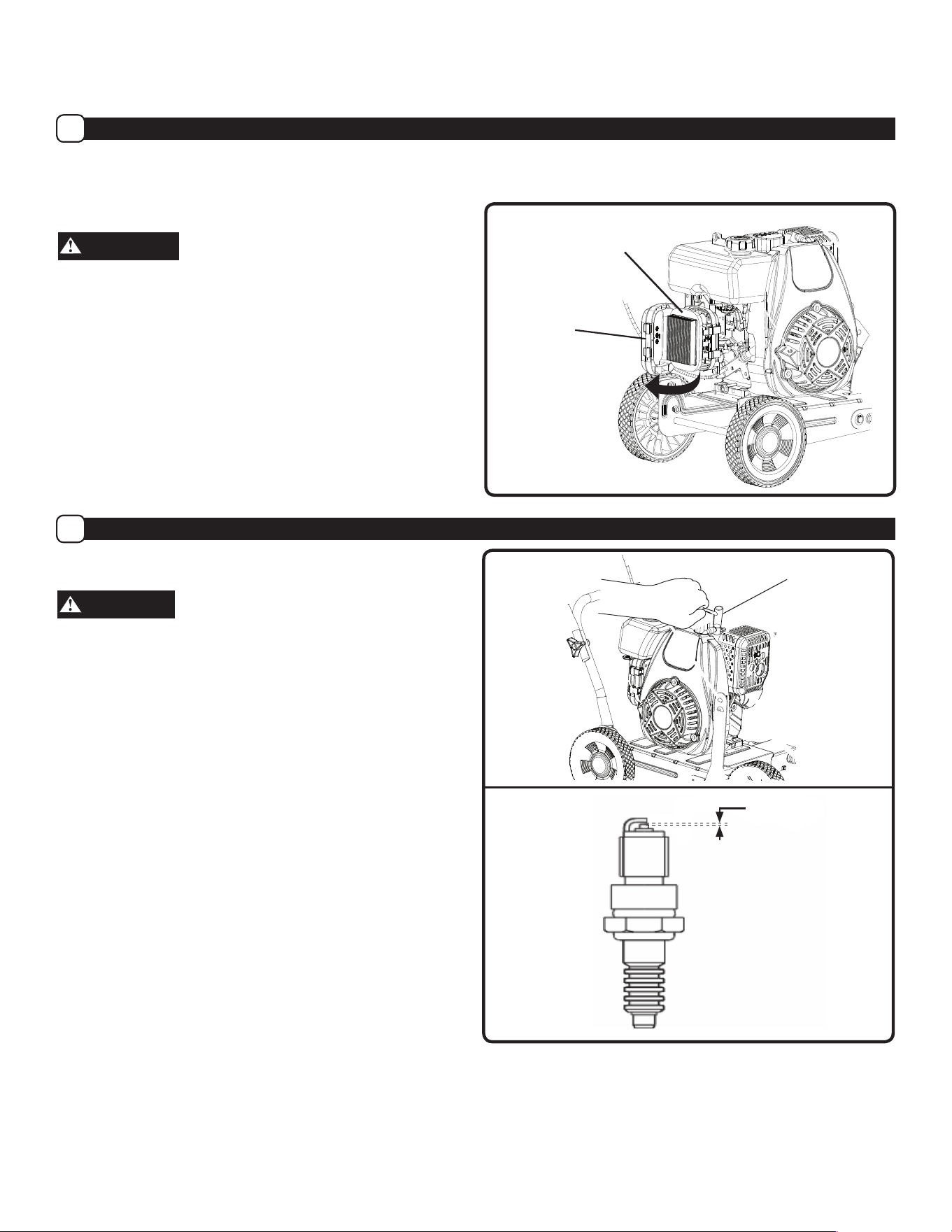
How to Check the Spark Plug
H
Spark Plug Model: Torch E7RTC
CAUTION
Only use the recommended spark plug or a spark plug
with the same temperature range. Using an improper spark
plug, an incorrect spark plug gap, or a dirty/fouled spark
plug can reduce engine performance and cause damage.
1. Stop engine and allow it to cool.
2. Remove spark plug wire from spark plug. Remove spark
plug (See Figure 15)
3. Visually inspect the spark plug for cracks or damage. If
cracked, replace spark plug.
4. Clean carbon deposits. If excessive carbon build up,
replace spark plug.
5. Check that the gap of the spark plug is 0.024-0.028 in.
(0.6-0.7 mm). (See Figure 16)
6. Re-insert the spark plug and tighten using a spark
plug wrench. (See Figure 15)
7. Reattach spark plug wire to spark plug.
NOTE: Torque of spark plug is 18-22 foot-pounds
(25-30 Nm).
WARNING
Never clean air filter with gasoline or an easy ignited
solvent because it may cause explosion.
NOTE:
Refer to Figure 14 when following the steps below:
Spark Plug
Wrench
Maintenance (Continued)
• Save all instructions
G
How to Clean the Air Filter
A dirty air filter will restrict air intake. Regular maintenance
of air cleaner will help improve engine performance and
reduce emissions.
Air Filter Element
Figure 14
Figure 15
0.024 - 0.028 in
0.6 - 0.7 mm
Figure 16
Air Filter Cover
1. Open the air filter cover.
2. Remove the air filter cover.
3. Carefully remove air filter element to prevent dirt
fromfalling into carburetor.
4.
Clean all parts. Wash the air filter element in a
nonflammable or high burning point solvent, and allow to
dry thoroughly; dip the filter element in clean oil, and
squeeze out all excess oil.
15
5. Reinstall the air filter element. Replace.
6. Close the air filter cover.

16
How to Prepare for Storage
I
WARNING
Never store the edger indoors with fuel in the fuel tank.
Never store in an enclosed, poorly ventilated area where
on a furnace, water heater or clothes dryer. Allow engine to
cool before storing unit.
WARNING
or while you smoke. Gasoline fumes can cause an explo-
NOTE: A yearly checkup or tune-up at an authorized service
center will make sure that the edger will provide maximum
performance for the next season.
To prevent fuel gum deposits and corrosion in the unit’s
carburetor and fuel system, it is highly recommended to
use a fuel additive/stabilizer formulated for ethanol fuels.
Follow the stabilizer manufacturer’s instructions. Run the
engine for at least 5 minutes after adding stabilizer.
When the edger is put in storage for thirty days or more,
the following steps should be followed to make sure the
edger is in good condition the next season.
1. Let the engine run until it is out of gasoline. Remove
the carburetor screw from bowl and drain fuel. Tilt unit
slightly to remove all fuel. Replace screw.
2. Change the oil by following instructions under
How to Change the Oil.
3. Remove the spark plug from the cylinder. Pour one
ounce (US) of oil into the cylinder. Slowly pull the
Maintenance (Continued)
• Save all instructions
recoil-start grip so that the oil will protect the cylinder.
Install a new spark plug in the cylinder. Pull starter
handle slowly a few times to distribute oil. Pull recoil
slowly until resistance is felt. This will close the
cylinder valves.
WARNING
Do not attach spark plug wire to spark plug when storing
unit.
4. Clean edger. Remove all dirt, leaves, debris, grease,
etc. from the edger - including cylinder cooling
fans, recoil starter cover holes, under fuel tank, and
5. Check the edger for worn or damaged parts. Have
damaged parts replaced if necessary.
6. Tighten any loose hardware.
7. Apply lubrication as directed in Maintenance section.
8. Put the unit in a building that has good ventilation.
9. Cover the edger with a breathing material.

17
PROBLEM POSSIBLE CAUSE(S) SOLUTION(S)
Engine difficult to start 1. Out of fuel
2. Start lever is not compressed
3. Choke in “Run / Warm Start”
position
4. Spark plug wire disconnected
5. Fouled spark plug
6. Dirty Carburetor
7. Clogged air filter
8. Clogged fuel filter
9. Contaminated Fuel
1. Add fresh fuel
2. Pull start lever against handle
3. Rotate Choke lever to “Choke / Cold Start”
position
4. Attach spark plug wire to spark plug
5. Remove spark plug. Inspect. Replace if
necessary
6. Take unit to an authorized service center
for Carburetor cleaning
7. Remove and clean air filter
8. Remove fuel filter. Inspect. Replace if
necessary
9. Drain fuel tank. Clean fuel tank. Fill with
fresh fuel
Engine Problems
Engine smokes excessively
Engine runs very “rough”
Engine runs erratically
Engine cannot maintain full speed
1. No Engine Oil
2. Engine oil not at proper level
3. Fouled spark plug
4. Clogged air filter
5. Clogged fuel filter
6. Contaminated Fuel
7. Carburetor out of adjustment
8. Choke in “Choke / Cold Start”
position
1. Add engine oil
2. Check engine oil. Add or drain engine oil if
necessary
3. Remove spark plug. Inspect. Replace if
necessary
4. Remove and clean air filter
5. Remove fuel filter. Inspect. Replace if
necessary
6. Drain fuel tank. Clean fuel tank. Fill with
fresh fuel
7. Take unit to an authorized service center
for Carburetor adjustment
8. Rotate Choke to “Run / Warm Start”
position
Excessive vibration / noise 1. Loose parts
2. Engine problems (above)
1. Tighten all fasteners
2. Refer to engine solutions (above)
Blade will not rotate 1. Debris interfering with blade
2. Blade loose
3. Belt Loose
1. Remove debris from around blade
2. Tighten blade nuts
3. Replace Belt
Engine will not stop
Engine flameout control line is
too tight.
Adjust the engine flameout control line
tighten nut to make the control line loose.
Blade will not cut properly Damaged or worn blade Replace blade
Frequent engine stalling 1. Excessive edging speed / depth
2. Engine problems (above)
1. Edge at a moderate pace. Make multiple
passes
2. Refer to engine solutions (above)
Troubleshooting
• Save all instructions