Warning: The Engine Exhaust from this product contains chemicals known to
the State of California to cause cancer, birth defects or other reproductive harm.
support@pulsar-products.com
866-591-8921
DO NOT RETURN TO STORE!
STOP
HAVE QUESTIONS OR NEED SERVICE?
Model No.
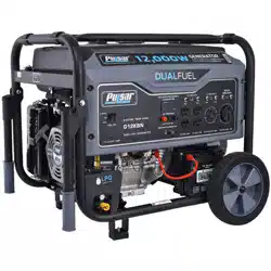
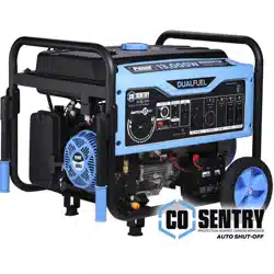
PG12000BCO
12000 Watt Dual-Fuel Open Frame Generator
OPERATOR’S MANUAL
2
Table of Contents
Introduction
Safety Warnings and Notices
Thank you for choosing Pulsar Products!
This manual provides instruction on how to operate and use your
generator safely and correctly; be sure to read and understand
this manual before using your generator. If you have ANY questions,
please phone 866.591.8921 M-F or [email protected]
BEFORE using your generator.
All details and images in this Manual are believed to be
accurate at the time of publication.
Pulsar Products reserves the right to make updates to this manual
at any time.
Please contact Pulsar Support at 866.591.8921 or
[email protected] for the latest updates.
This manual is a permanent part of the generator set. If the
generator is resold, kindly include this manual with the generator.
WARNING: Save This Manual For Future
Reference
This manual contains important information regarding the safety,
operation, maintenance, and storage of this product. Before use,
read carefully and understand all cautions, warnings, instructions,
and product labels. Failure to do so could result in serious personal
injury and/or property damage.
The words DANGER, WARNING, CAUTION, and NOTICE are used
throughout this manual to highlight important information. Make
sure that the meaning of this safety information is known to all
who operate, perform maintenance on, or are near the generator.
This safety alert symbol appears with most safety
statements. It means to pay attention and be alert, your safety is
involved! Please read and abide by the message that follows the
safety alerts symbol.
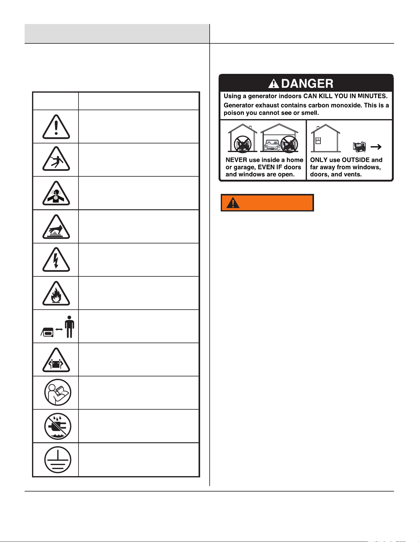
Safety Symbols
Follow all safety information contained in this manual and on the
generator.
DANGER indicates an imminently hazardous situation which,
if not avoided, will result in death or serious injury.
WARNING indicates a potentially hazardous situation which,
if not avoided, could result in death or serious injury.
CAUTION indicates a potentially hazardous situation which,
if not avoided, may result in minor or moderate injury. It
may also be used to alert against unsafe practices.
Failure to follow the instruction may result in the damage
to your generator and other property.
Safety Warnings. .........................1
Safety Instructions . .... ..................2
CO Sentry . ..............................4
Names of Components . ...................6
Control Panel . ...........................7
Specifications . ..........................8
Assembly . ..............................9
DANGER
WARNING
CAUTION
NOTICE
Safety Definitions
Preparation . .. .........................11
Battery. ................................11
Adding Engine Oil. .......................12
Connecting a Propane Tank . ..............14
Operation. ..............................16
Maintenance . .......................... 20
Troubleshooting . ........................24
3
Safety Instructions
Before operating your generator, you must read and
understand the manual and familiarize yourself with the safe
operation practices.
Install battery-operated carbon monoxide alarms or plug-in carbon
monoxide alarms with battery backup according to the
manufacturer's instructions. Most smoke alarms cannot detect
Operate this product ONLY outside far away from windows, doors,
and vents to reduce the risk of carbon monoxide gas from
accumulating and potentially being drawn towards occupied spaces.
carbon monoxide gas.
DO NOT run this product inside homes, garages, basements,
crawlspaces, sheds, or other partially enclosed spaces even if using
fans or opening doors and windows for ventilation. Carbon monoxide
can quickly build up in these spaces and can linger for hours, even
after this product has shut off.
ALWAYS place this product downwind and point the engine exhaust
away from occupied spaces. If you start to feel sick, dizzy, or weak
while using this product, shut it off and get to fresh air
IMMEDIATELY - then see a doctor; you may have carbon monoxide
poisoning.
Safety Alert Symbol
4 FEET
SYMBOL DESCRIPTION
Ground. Consult with electrician to
determine grounding requirements before
Electrocution Hazard
Asphyxiation Hazard
Burn Hazard. DO NOT touch hot surfaces.
Electrical Shock Hazard
Fire Hazard
Maintain Safe Distance
Lifting Hazard
Read Manufacturer’s Instructions
DO NOT Operate in Wet Conditions
Safety Precautions
POISONOUS GAS HAZARD: Engine exhaust contains carbon
monoxide, a poisonous gas that could kill you in minutes. You
CAN NOT smell it, see it, or taste it. Even if you do not smell
exhaust fumes, you could still be exposed to carbon monoxide
gas.
WARNING
4
Safety Instructions
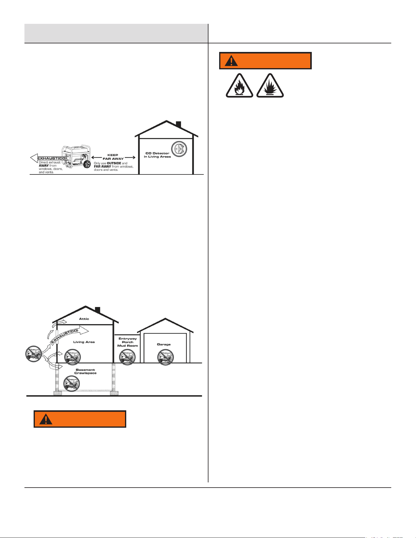
Correct Usage
Example location to reduce risk of carbon monoxide poisoning
• ONLY use outside and downwind, far away from windows,
doors, and vents.
• Direct exhaust away from occupied spaces.
Incorrect Usage
Do not operate in any of the following locations:
• Near any door, window, or vent
• Garage
• Basement
• Crawl Space
• Living Area
• Attic
• Entry Way
• Porch
• Mud Room
When Adding Or Draining Gasoline
Turn the generator engine OFF and let it cool for at least 2 minutes
before removing the fuel cap. Loosen the cap slowly to relieve
pressure in the tank.
• Fill or drain fuel tank outdoors.
• DO NOT overfill the tank. Allow space for fuel expansion.
• If fuel spills, wipe it up and let the area dry before starting the
engine.
• Keep fuel away from sparks, open flames, heat, and other ignition
sources.
• Check fuel lines, tank, cap, and fittings frequently for cracks or
leaks; replace if necessary.
• DO NOT light a cigarette or smoke anything.
When Starting Equipment
• Ensure spark plug, muffler, fuel cap, and air cleaner are in place.
• DO NOT crank engine with spark plug removed.
When Operating Equipment
• DO NOT operate this product inside any building, carport, porch,
mobile enclosure, marine applications, or shed.
• DO NOT tip engine or equipment at an angle that causes fuel
to spill.
• DO NOT stop the engine by moving the choke control the to
“Start" position.
• DO NOT exceed the generator's wattage capacity.
• Start the generator and the let engine stabilize before connecting
electrical loads.
• Connect electrical loads in the OFF position, then turn ON for
operation.
• Turn electrical loads OFF and disconnect from the generator before
stopping the generator.
Fuel and its vapors are extremely flammable and explosive which
could cause burns, fire, or explosion resulting in death or serious
injury and/or property damage.
WARNING
Starter cord kickback (rapid retraction) could pull hand and
arm toward the engine faster than you can let go which
could cause broken bones, fractures, bruises, sprains, or
other serious injuries.
WARNING
5
Safety Instructions
Improper treatment of the generator could damage it and
shorten its life.
• Use generator only for intended applications.
• If you have questions about intended use, ask a dealer or
contact your local Pulsar service center.
• Operate generator only on solid, level surfaces.
• DO NOT expose the generator to excessive moisture, dust,
dirt, or corrosive vapors.
• DO NOT insert any objects through cooling slots.
• If connected devices overheat, turn them off and disconnect
them from the generator.
Shut off the generator if:
• Electrical output is lost.
• Equipment sparks, smokes, or emits flames.
• Unit vibrates excessively.
Parallel Kit Precautions
Carbon Monoxide Safety
Carbon Monoxide
Generators are very convenient, but they can also be very
dangerous. All fuel-burning appliances and equipment release
a poisonous gas called carbon monoxide. Carbon monoxide
(also known as CO) can be dangerous for humans and pets,
even in small amounts, because it blocks oxygen from getting
into your body. Carbon monoxide poisoning can lead to death in
a very short time. It is odorless, tasteless and invisible, so you
may be exposed without knowing it. That is why carbon
monoxide is sometimes called “the silent killer.”
To prevent serious injury, death, and generator and/or
equipment damage from electric shock and fire:
1. Follow Parallel Kit instructions provided with it for
connection and use of a Parallel Kit.
2. Only connect two identical Inverter Generators together
using a Parallel Kit.
3. Connect Parallel Kit only to terminals marked “Parallel”
on the front of the Generator.
4. Do not remove or connect a Parallel Kit while the
Generator is running.
5. Do not use a Parallel Kit that is attached to only one
Generator.
WARNING
NOTE
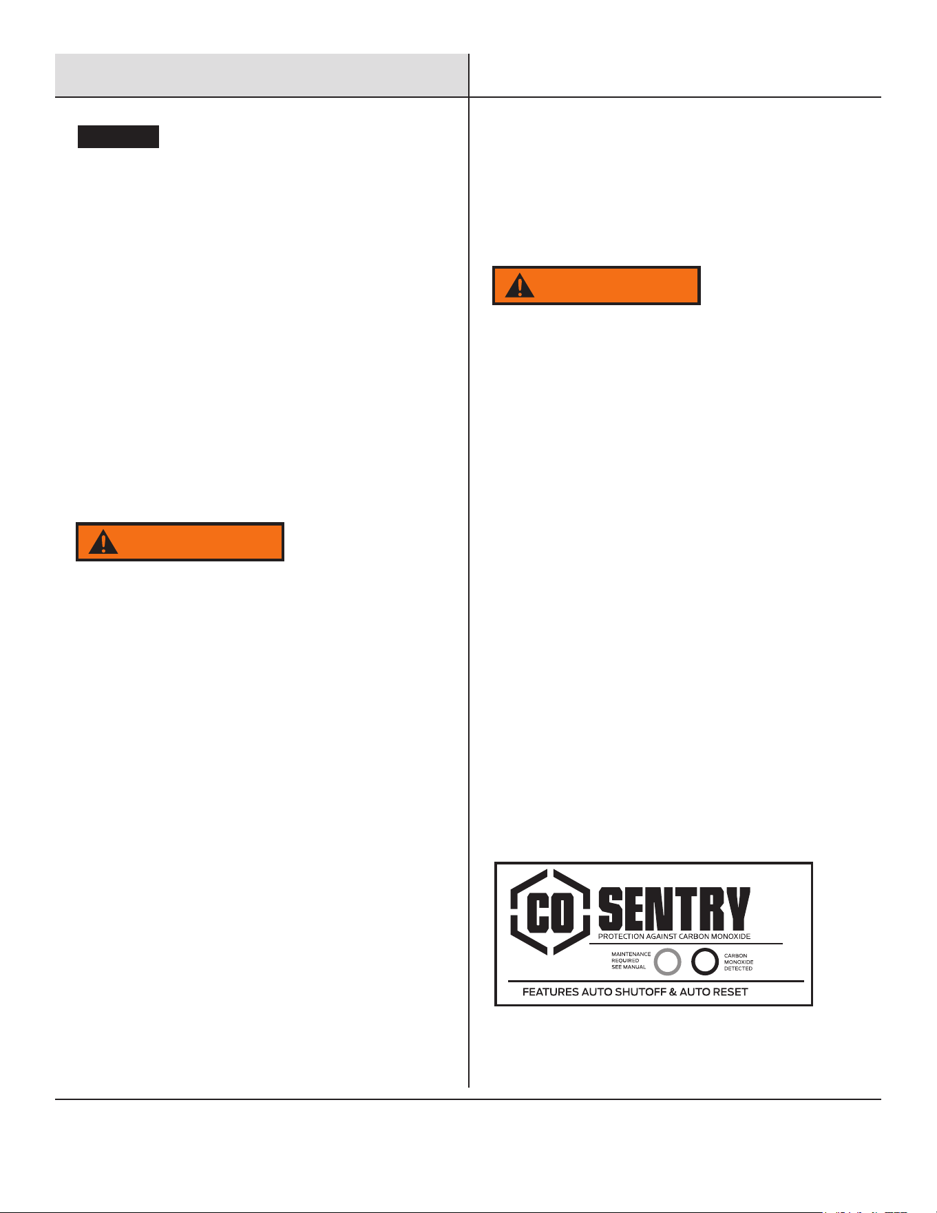
CO Sentry
The CO Sentry system was created to protect from dangerous
carbon monoxide. Just like the detector for your home the CO Sentry
tests the air for dangerous levels of carbon monoxide. If dangerous
levels of carbon monoxide are detected this generator will
automatically shut off.
CO Sentry Indicator Lights
RED
Carbon monoxide has accumulated around the generator. After
shut off, the RED indicator light in the CO Sentry area of the control
panel will flash to provide notification that the generator was shut off
due to an accumulating CO hazard. The RED light will flash for at least
five minutes after a CO shut off. Move the generator to an open,
outdoor area far away from occupied spaces with exhaust pointed
away. Once relocated to a safe area, the generator can be restarted.
Introduce fresh air and ventilate the area where the generator had
shut down.
YELLOW
A CO Sentry system fault occurred. When a system fault occurs, the
generator is automatically shut down and the YELLOW indicator light
in the CO auto shut off area of the control panel will flash to provide
notification that a fault has occurred. The YELLOW light will flash for
at least five minutes after a fault. The generator can be re-started,
but may continue to shut off.
WARNING
Automatic shut off accompanied with a flashing RED light in the
CO Sentry portion of the control panel is an indication that the
generator was improperly located. If you start to feel sick, dizzy,
weak, or carbon monoxide detectors in your home indicate
an alarm, get to fresh air immediately. Call emergency services.
You may have carbon monoxide poisoning.
6
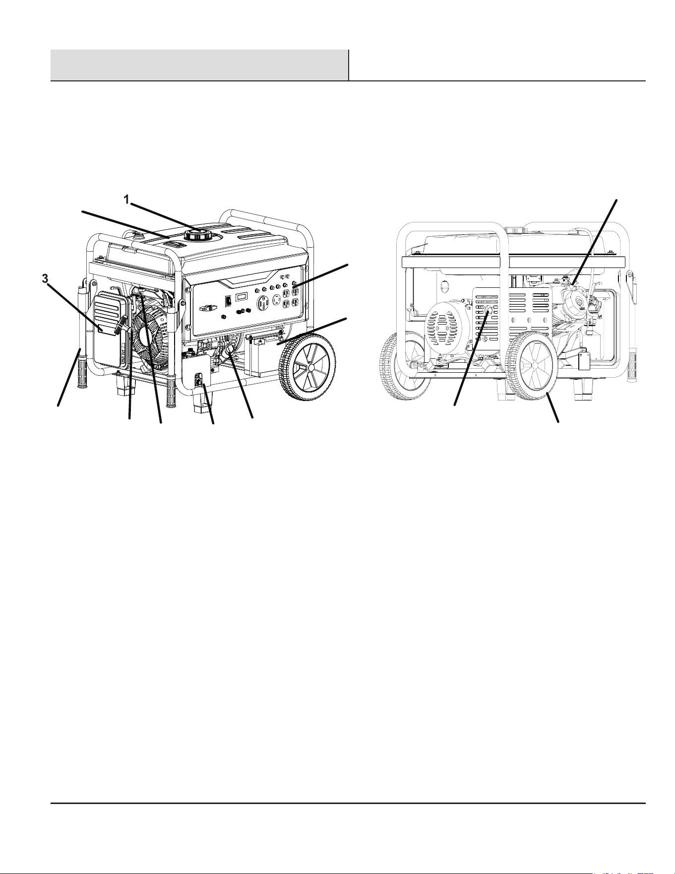
Components
Before operating your generator, you must read and
understand the manual and familiarize yourself with the
safe operation practices.
1. Fuel Cap : Add fuel here.
2. Fuel gauge : Used to observe fuel conditions.
3. Air filter : Clean or replace the air filter.
4. Control Panel : The control panel contains the outlets and operational controls.
5. Battery : Connect before start
6. Oil dipstick : Unscrew the oil dipstick to check oil levels and add oil when needed.
7. LPG Supply Hose and Inlet Connector : Gas connections must be secure, tight and comply with
all local regulations.
8. Recoil Handle : Pull the recoil handle to manually start the engine.
9. Carburetor : If storing the generator for longer than six months, drain the fuel tank to prevent fuel
separation, deterioration, and deposits in the fuel system.
10. Carry Handles : Helps transport the generator.
11. Spark Plug Cover : Spark plug can be maintained after removing this cover.
12. Transport Wheels : Helps transport the generator
13. Muffler and Spark Arrestor : The spark arrestor prevents sparks from exiting the muffler.
11
2
4
5
10
8
9
7
6
13
12
7
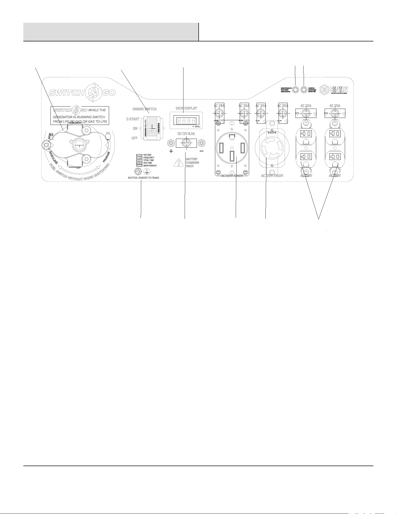
Control Panel
1. Fuel Selector Switch: Used to select Gasoline or Propane.
2. Engine Off/On/start Switch
3. Data Display: Push the mode button to cycle through the data display modes. (Voltage, Frequency (Hz),
Lifetime Hours, Run Time, Maintenance Codes)
4. CO Sentry Indicator Lights: The CO Sentry monitors the accumulation of poisonous carbon monoxide gas. If
increasing levels of CO gas are detected, the CO Sentry automatically shuts down the engine.
5. Ground Terminal: The ground terminal is used to externally ground the generator.
6. DC 12 volt, 8.3 Amp binding posts
7. 120/240 volt, 50 Amp, AC receptacle with Circuit Breaker.
8. 120/240 volt, 30 Amp, AC receptacle with Circuit Breaker.
9. 120 Volt, 20 Amp, AC Duplex Receptacle with Circuit Breaker.
①
②
③
④
⑤
⑥
⑦
⑧
⑨

8
Specifications
Model
Engine Type
Displacement
Rated Power (kW) Gasoline
Peak Power (kW) Gasoline
Rated Power (kW) LPG/Propane
Peak Power (kW) LPG/Propane
Rated Voltage
Rated Frequency
Phase
Starting Type
Fuel Type
Fuel Capacity
Oil Type
Oil Capacity
Maximum Ambient Temperature
PG12000BCO
Single Cylinder, Four Stroke, Air Cooled
Gasoline Engine
457cc
9.5
12
8.55
10.8
120V/240V
60Hz
Single Phase
Recoil, Electric Start
Regular Gasoline
8 Gallons
10w-30
1.1L (37.2oz)
104°F (40° C)
9
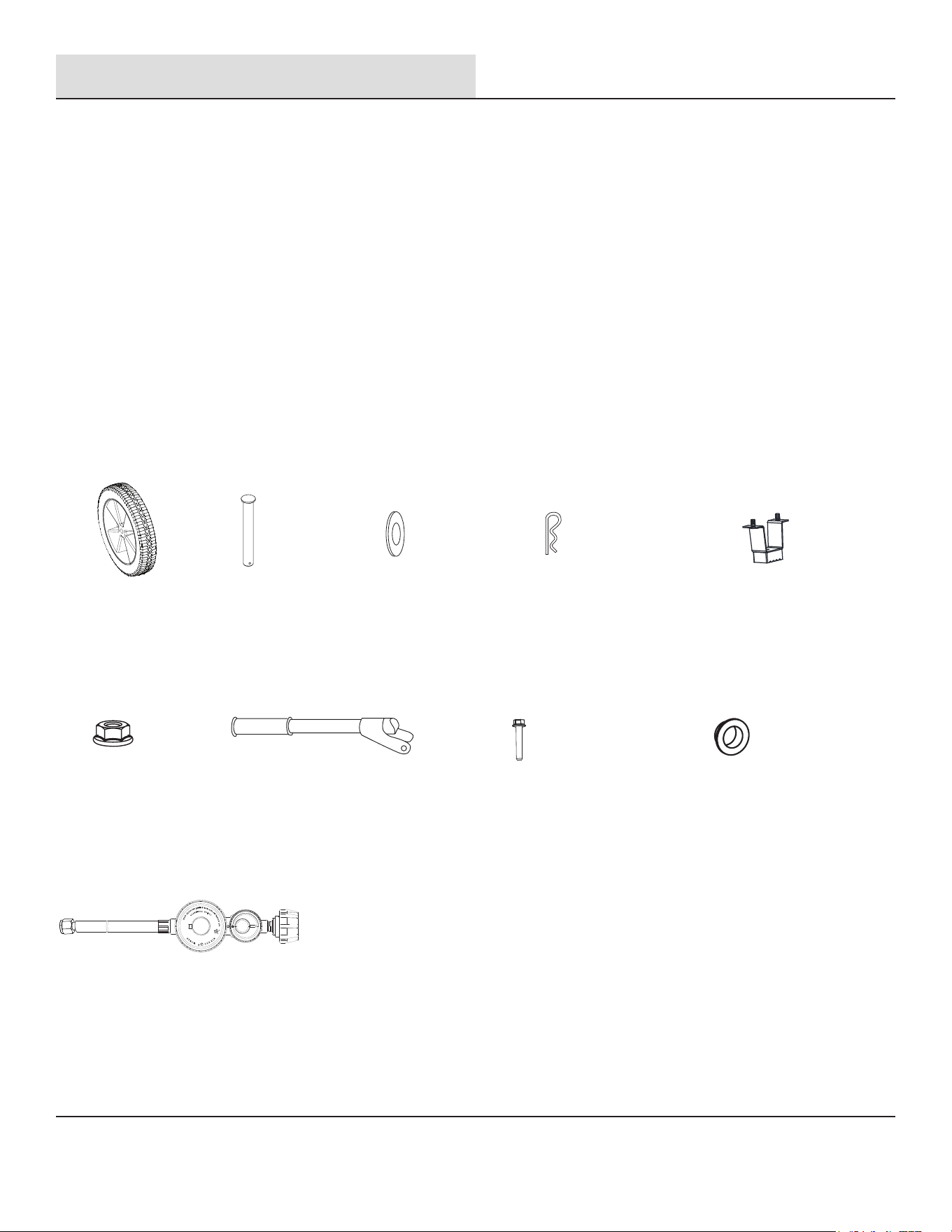
① 2 xWheels
② 2 xAxle
③ 2 xWasher
④ 2 xCotter pins
⑤ 2 xSupporting Feet
⑧ 2 xBolts (M8x50)
⑥ 6 xNuts (M8)
⑦ 2 xCarry Handles
⑨ 4 xBushings (Flanged)
Included Accessories
• Warranty Card
• Operator 's Manual
• Spark Plug Wrench
• Combination Wrench
• Funnel
• Measuring cup
⑩ 1 xPropane connection hose
Preparation
Your generator requires some assembly. This generator ships from our factory without oil; it must be properly filled with oil before
operation.
Unpacking
1. Set the shipping carton on a solid, flat surface.
2. Remove everything from the carton except the generator.
3. First, assemble the wheels and carry handles. It is suggested to cut the panel of the carton to facilitate assembly (minimum
two people cooperation is required). Please refer to page 10 for the wheel and carry handle assembly steps.
4. Using the carrying handles of the unit, carefully remove the generator from the box.
Packing List
Check all loose parts to the following list. Contact your dealer if any loose parts are not included.
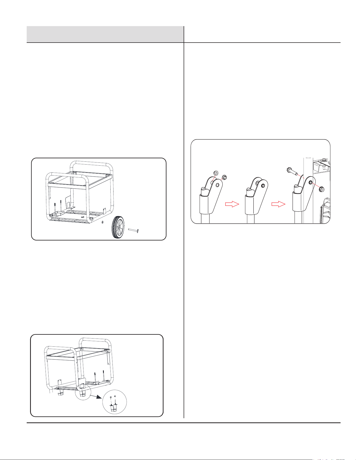
Assembly
10
• Parts needed -① 2×wheels, ②×2 axles,
2×washers, and ④ 2×hair pins.
• Raise or tilt generator so you can slide the
wheel
axle pin into the wheel, the washer, the
wheel
mounting hole located
on the side of the
frame.
• Secure the wheel assembly by inserting a hair
pin
through hole at the end of the wheel axle
and
pressing until it locks into place.
• Repeat this process to install the other wheel.
Wheel assembly (See Fig 1)
Fig 1
①
②
③
④
↗
↗
↗
↗
Support Leg assembly (See Fig 2)
Fig 2
• Parts needed - ⑤ 2×Support Leg, ⑥ 4×Nuts (M8).
• Raise the front end of the generator high enough to
gain access to the bottom of the frame. Securely
position props underneath to support.
• Align the support legs with the holes in the
generator frame and tighten the screws exposed by
the support legs with nuts.
• Repeat this process to install the other support leg.
↗
↗
⑥
⑤
• Parts needed -⑥ 2xNuts(M8), ⑦ 2xCarry handles,
⑧ 2xBolts(M8x50),and ⑨ 4xBushings (Flanged).
• Place 2 bushings on handle and slide handle in place
with the pre-drilled hole on the generator frame.
• Insert bolt through the handle and frame and tighten
with nut.
• Repeat this process to install the other carry handle.
Carry Handles assembly (See Fig 3)
Fig 3
↗
↗
⑨
⑥
⑦
⑧
↗
↗
Assembly
11
Preparation
CAUTION
NOTICE
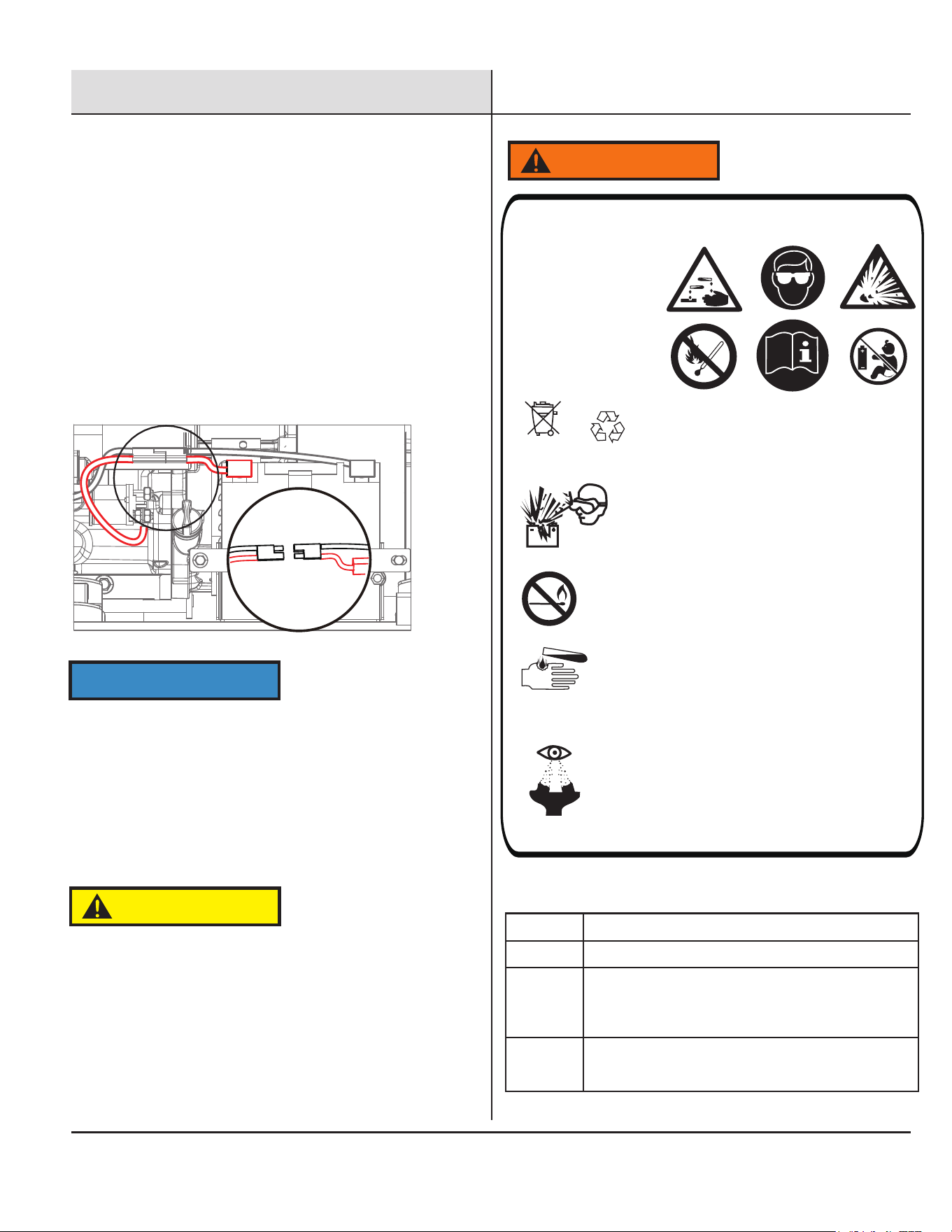
Preparation
The generator battery is shipped disconnected for
safety. You must connect the battery quick-connect
cables before using the generator.
Connecting the battery (See Fig 4)
• A quick connect battery plug is pre-installed on the
battery and the generator, connect both together as
shown.
• Never attempt to connect different colored battery
wires together!
Fig
4
Cover the terminals with the rubber covers When
removing the battery for replacement: Remove the nut
and bolt first from the negative (Black) post, then from
the positive (Red) post, being careful not to short across
the terminals. Always abide by the safety warnings
provided with the battery. Remove the battery and
dispose of it according to your local and state
regulations.
Quick-Connect Plug
NOTE:
• When the engine is running, this generator will add
charge back to the battery, much the same as an
automobile does.
• Also, like an automobile, if the battery sits for several
months, without use, the battery may need an external
charge to start the generator electrically.
NON-SPILLABLE SEALED BATTERY
WARNING
WEAR EYE PROTECTION,EXPLOSIVE GASES CAN
CAUSE BLINDNESS OR INJURY.
DO NOT SMOKE OR SPARK NEAR THE BATTERY
SULFURIC ACID CAN CAUSE BLINDNESS OR
SEVERE BURNS
IF ELECTROLYTE CONTACT THE SKIN WASH THE
AREA IMMEDIATELY WITH CLEAN WATER
IF YOU GET ELECTROLYTE CONTACT WITH YOUR
EYE,RINSE IMMEDIATELY WITH CLEAN WATER
AND SEEK MEDICAL ATTENTION.
3E
Antidotes for battery acid
CONTACT TREATMENT
External Flush with water.
Internal
Drink large quantities of milk or water, followed
by milk of magnesia, vegetable oil or beaten
eggs. Get immediate medical attention.
Eyes
Flush with water. Get immediate medical
attention.
This is a ready
filled, activated
sealed battery.
Never remove
strip.
12
Preparation
Preparation
Your generator requires some assembly. This
generator ships from our factory without oil; it must
be properly filled with oil before operation.
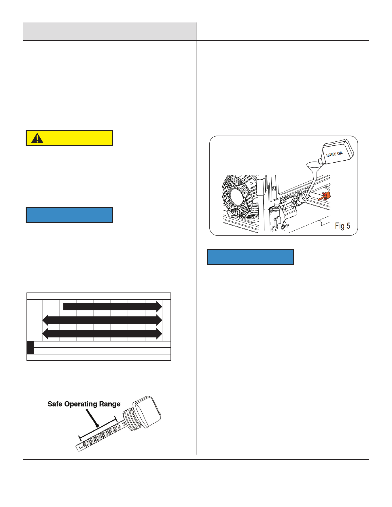
If running the generator in extreme temperatures,
refer to the following chart for recommended oil type.
Add Engine Oil
DO NOT attempt to crank or start the engine before it
has been properly filled with the recommended type
and amount of oil. Damage to the generator from
failing to follow
these instructions will void your warranty.
CAUTION
Failure to follow this instruction may result in the
damage to your generator and other property.
NOTICE
NOTICE
-20 0 20 40 60 80 100 120
-28.9
°F
°C -17.8 -6.7 4.4 15.6 26.7 37.8 48.9
10W-30
5W-30 Synthetic
10W-405W-30
Recommended Engine Oil Type
Ambient temperature
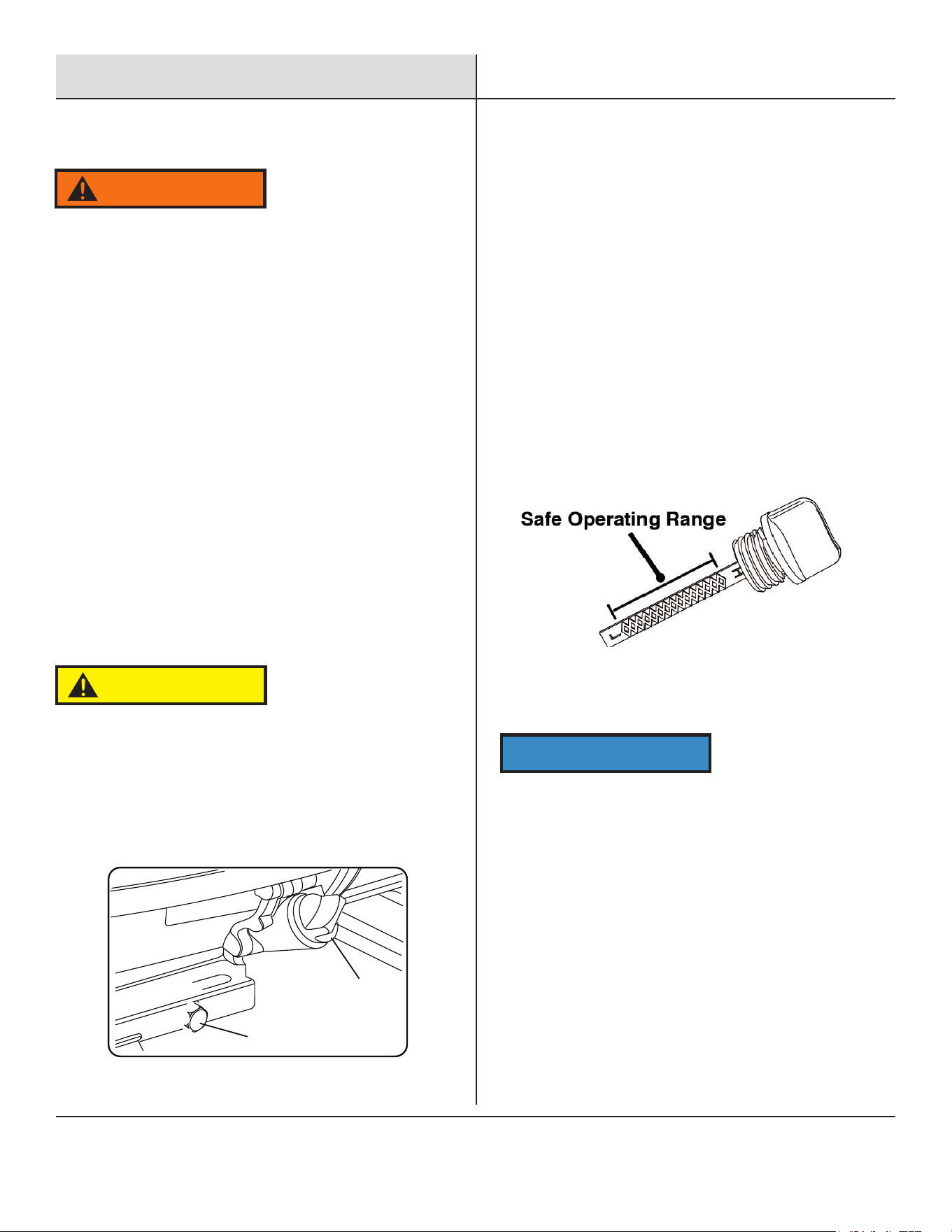
Residual oil from the factory may remain in the
engine, add oil slowly to prevent overfilling of the
engine.
Once the oil has been added, oil level should appear
1-2 threads below the fill hole. DO NOT screw in the
dipstick while checking.
1. Place the generator on a solid, flat, level surface.
2. Remove oil fill cap/dipstick to add oil.
3. Using a funnel, add the appropriate type of oil
until the oil level is at the proper level. SAE
10W-30 oil is recommended for general use. DO
NOT OVERFILL.Replace oil fill cap/dipstick and
secure cover.
NOTE: Check engine oil level before each use,
and add as needed.
13
Preparation
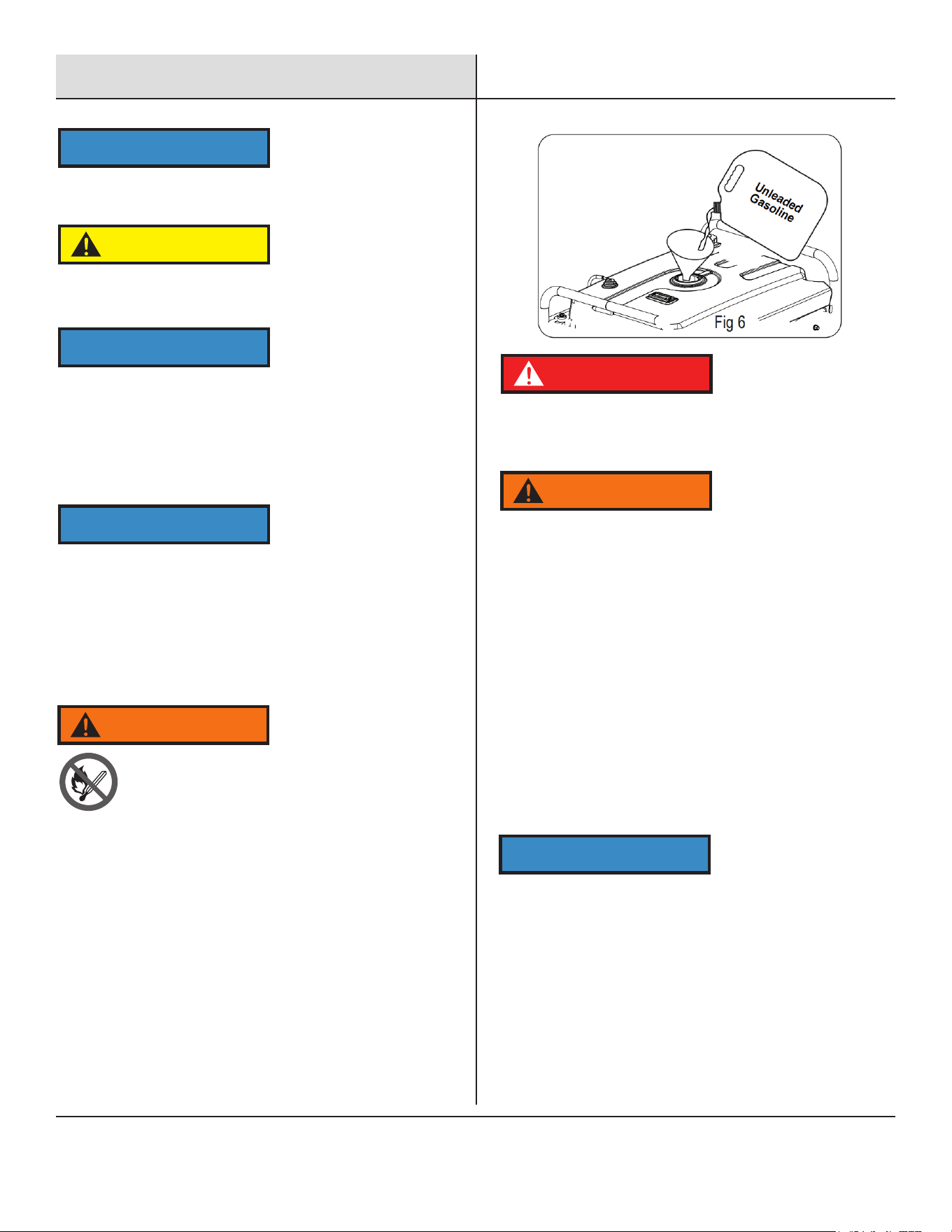
1. Set generator outdoors in a well-ventilated area, away from
structures and people.
2. Slowly remove fuel cap.
3. Insert a funnel into the fuel tank and carefully pour gasoline
into the tank until fuel level reaches 1 ½ inches below the
top of the neck. Be careful not to overfill the tank to allow
space for fuel expansion.
• To ensure that the generator runs smoothly use only FRESH,
FRESH
GASOLINE WITH AN OCTANE RATING OF 87.
• Never use old gasoline.
• Avoid getting dirt or water in the gasoline tank.
• Gasoline WILL age in the tank and make it hard to start the
generator
in the future.
• Never store generator for extended periods of time with
gasoline in
the tank.
This engine is equipped with a low oil shut-off and will stop
when the oil level in the crankcase falls below a critical level.
CAUTION
Check oil level often during the break-in period. Refer to the
Maintenance section for recommended service intervals.
NOTICE
The first 5 hours of run time are the break-in period for the
generator. During the break-in period stay at or below 50% of
the running watt rating and vary the load occasionally to allow
stator windings to heat and cool. Adjusting the load will also
cause the engine speed to vary slightly and help seat the piston
rings. After the 5-hour break-in period, change the oil.
NOTICE
Synthetic oil may be used after the 5-hour initial break-in
period. Using synthetic oil does not increase the recommended
oil change interval. Full synthetic 5w-30 oil will aid in starting in
cold < 41° F (5° C) temperatures.
NOTICE
TO PREVENT SERIOUS INJURY FROM FIRE:
Fill the gasoline tank in a well-ventilated area away from ignition
sources. If the engine is hot from use, shut the engine off and wait
for it to cool before adding gasoline. Do not smoke.
WARNING
Add Gasoline( Fig. 6 )
Do not overfill the gasoline the tank. Overfilling can result in a
fire, explosion, or death.
Gasoline can expand. Do not fill the gasoline tank to the top.
Leave a minimum of 1.5 inches open space. Gasoline fumes
are explosive. Do not fill the tank near an open flame. Always
check for gasoline spills.
DANGER
WAR NI NG
• Propane tanks that use liquid withdrawal system can not be
used on these models.
• Confirm that the re-qualification date on the tank has not
expired.
• DO NOT use included LPG hose for any other appliances.
NOTICE
Connecting a Propane Tank
1
2
3
14
Preparation-
Propane
• All new propane tanks must be purged of air and
moisture prior to filling. Used propane tanks that have
not been plugged or kept closed must also be purged.
The purging process should be done by a propane
tank supplier (propane tanks from an exchange
supplier should have been purged and filled properly).
• ALWAYS position the propane tank so the connection
between the valve and the gas inlet will not cause
sharp bends or kinks in the hose.
NOTICE
WARNING
Explosion hazard. DO NOT start generator if you smell
propane. ALWAYS fully close the LPG tank valve and
disconnect the propane hose from the generator
when not in use.
Nevert invert (turn up side down) a LPG tank while in
use.
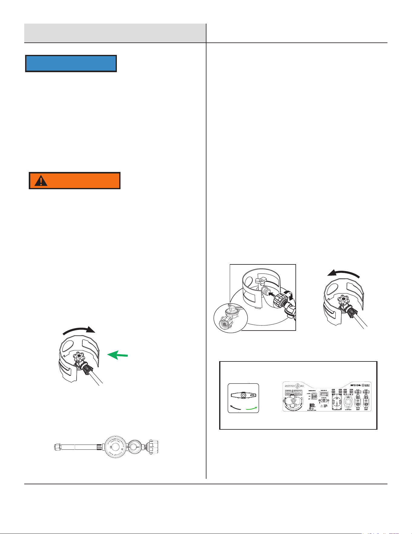
Connecting a Propane Tank
1. Turn the generator OFF and leave on a flat surface
in a well ventilated area.
2. Verify that the propane tank valve is in the fully
closed position.
3. Remove the cover on the generator gas inlet.
4. Install the propane hose securely on the gas inlet
(threaded tight) and check for a secure connection.
5. Remove the safety plug or cap from the propane tank
valve and attach the other end of the hose to the LPG
connector on the tank, hand-tighten. Then turn the fuel
selector switch to "propane".
6. Turn the propane tank valve to the fully open position.
Check all connections for leaks by wetting the fittings
with a solution of soap and water. Bubbles which appear
or bubbles which grow indicate that a leak exists. If a
leak exists at a fitting, turn the propane tank valve to the
fully closed position and tighten the fitting. Open the
propane tank valve and recheck the fitting with the soap
and water solution. If the leak continues or if the leak is
not at a fitting then DO NOT use the generator and
contact an authorized Pulsar service center.
CLOSE
OPEN
IMPORTANT: DO NOT use thread seal tape or any other
type of sealant to seal the propane hose connection.
PROPANE
↗
LPG
GASOLINE
PROPANE
Fuel Selector Switch
15
Preparation
WARNING
Grounding The Generator
A generally acceptable grounding wire is a No. 12 AWG (American
• Connect the other end to a copper or brass grounding rod that’s
Attach grounding wire (if required by code)
driven into the earth.
Wire Gauge) stranded copper wire.
Grounding codes vary by location. Please contact a local
• Ground the generator by connecting
a sutible grounding
cable to the
groundin
g stud on the panel and tighting the nut.
electrician to check the grounding regulations for your area.
Failure to properly ground the generator can result in
electrocution.
Connecting Generator to a Building Electrical
System
If connecting generator to a building electrical system for
standby power, you must use a qualified electrician to
install a transfer switch. The power from the generator
must be isolated from the utility power source. The connection
must comply with all electrical codes and applicable laws.
Never handle the generator, electrical devices, or any cord while
standing in water, while barefoot, or when hands or feet are wet.
Always keep the generator dry. Never store or operate generator
in rain or under wet conditions.
Use a ground fault circuit interrupter (GFCI) in a damp or highly
conductive area, such as metal decking or steel work.
Never plug electrical devices into generator having frayed, worn,
or bare wires. Never touch bare wires or contact receptacles.
Never permit a child or unqualified person to operate generator.
Always keep children a minimum of 10 feet away from the
generator.
If using the generator for backup power, notify the utility
company.
If connecting generator to a building’s electrical system for
standby power, you must use a qualified electrician to install a
transfer switch. Failure to isolate the generator from the power
utility could result in serious injury or death to electric utility
workers.
16
Operation
NEVER operate the generator inside any building, garage,
basement, crawlspace, shed, or enclosure, including the
generator compartment of a recreational vehicle.
NEVER operate or start the generator in the back of an SUV,
camper, trailer, truck bed (regular sides, flat or other
configuration), under staircases, stairwells, next to walls or
buildings, or in any other location that will not allow for
adequate cooling of the generator or for the proper exit of the
exhaust flow.
DO NOT operate or store the generator in wet weather
conditions such as rain or snow. Using a generator in wet
conditions could result in serious injury or death due to
electrocution.
Generators must have a minimum of 5 feet (1.5 m) of clearance
from all combustible material.
Generators must also have a minimum of 5 feet (1.5 m) of
airflow clearance on all sides to allow for adequate cooling,
maintenance, and service.
Always place the generator in a well-ventilated area. NEVER
place the generator near air intake vents or where exhaust
fumes could be drawn into occupied or confined spaces.
Always carefully consider wind and air currents when
positioning the generator.
Always allow generators to cool completely before transport or
for storage purposes.
Failure to follow proper safety precautions may result in
personal injury, damage to the generator, and void the
manufacturer's warranty.
WARNING
WARNING
Generator Location
During operation, the muffler and exhaust fumes will become
hot. If there is inadequate cooling space or if the generator is
blocked or enclosed, temperatures can rise quickly and may
lead to a fire.
Starting The Generator
Place generator on a level surface. All electrical loads MUST be
disconnected from generator.
Check oil and fuel levels. If needed add oil, refill the LP gas cylinder,
add gasoline.
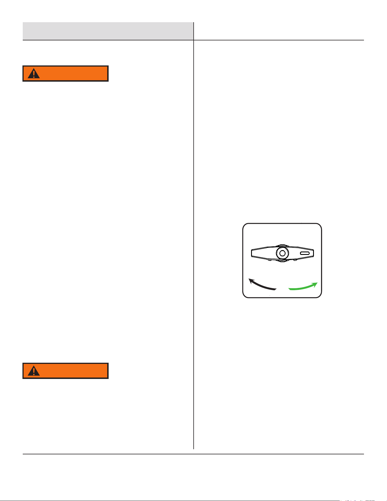
Using the fuel selector switch, select GASOLINE or PROPANE.
Set the Switch & Go to your desired fuel and shut off the alternate
fuel. (petcock for gasoline, tank valve for propane)
For propane, open the cylinder valve on the LP gas cylinder and turn
off the flow of gasoline.
The fuel source can be switched while the engine is off or while it is
running if a propane tank supply line is connected to the generator
BEEFORE operation.
If you switch from gasoline to another fuel source while the engine
is running, it may run rough for a few seconds as it purges gasoline
from the carburetor.
If the engine stops when switching fuel sources, disconnect all
loadsthen restart the unit on the fuel source of choice.
To switch to gasoline:
Turn the fuel valve to the open position to start the flow of gasoline.
Rotate the fuel selector switch to GASOLINE.
Turn off the flow of propane gas.
To switch to propane:
Open the cylinder valve on the LP gas cylinder to start the flow of
propane.
Rotate the fuel selector switch to PROPANE.
Turn off the flow of gasoline.
GASOLINE
PROPANE
Fuel Selector Switch
17
Operation
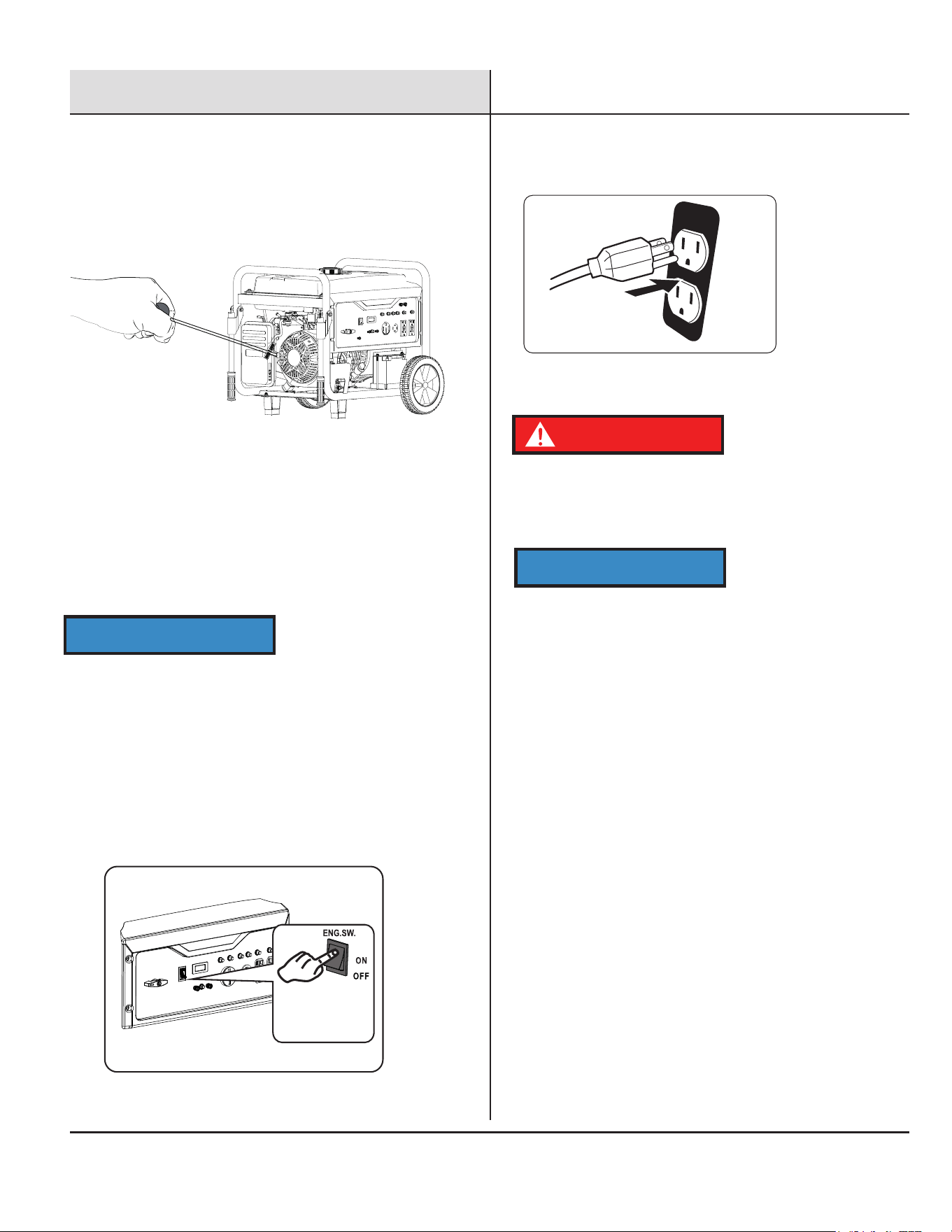
1. For Recoil Start: Firmly grasp and pull the recoil handle slowly
until you feel resistance, let it retract then pull swiftly. If it fails
to start successfully, wait for 3 seconds then repeat this step.
3. Plug in devices
1. The total combined load through the outlets on the generator
shall not exceed the running power of the generator.
2. If a main circuit breaker activates, turn off the connected
device, remove it from the port or outlet, and return the circuit
breaker to on position.
3. Restart the engine and reconnect devices while being careful to
not overload the generator.
Fire and explosion hazard. If the generator does not use propane,
always place the propane tank valve in the full off position or
disconnect the hose connection.
DANGER
NOTICE
When the engine is running, this generator will add charge back to
the battery, much the same as an automobile does. Also, like an
automobile, if the battery sits for several months, without use, the
battery may need an external charge to start the generator
electrically.
Circuit breaker
Low Oil Shut-Off
1. If the engine oil level is too low, the engine will automatically
shut off.
2. The engine cannot be restarted until the proper amount of oil
has been added.
NOTICE
When the battery state of charge is below 10.5v:
• The electric start and the gasoline solenoid may not work.
• Switch to propane and use the recoil to start the engine.
START
2. For electric start: Push and hold the engine switch in the
"START" position.
Do not hold the START/ON/OFF switch in
the “Start” position for more than 15 seconds. Allow 1 minute
between starting attempts.
• When using gasoline turn fuel valve to the "ON" position.
• Move the fuel selector to "GAS" position.
• Slide the choke lever to the "Choke" position. SKIP THIS IF
THE ENGINE IS WARM OR HOT.
• When using LPG move the fuel selector to "LPG" position.
• Slide the choke lever to the "Choke" position. SKIP THIS IF
THE ENGINE IS WARM OR HOT.
18
Operation
Stop The Engine
1. Remove any connected loads from the control panel
receptacles. Allow the generator to run at “ no load” o reduce
and stabiliz e engine and alternator temperatures.
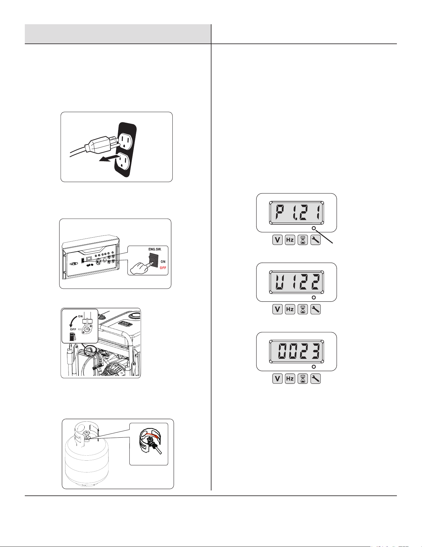
1.Turn the engine START/ON/OFF switch to the “OFF” position.
2.Turn the fuel valve lever back to the OFF position.
2. Move the engine START/ON/OFF switch to the “OFF” position.
3. Stop the flow of fuel.
Data Display
Push the mode button to cycle through the data display modes.
Voltage: Displays current voltage output.
Frequency (Hz): Displays power output frequency in Hertz.
Lifetime Hours: Displays the lifetime run hours.
Run Time: Displays current run time. Resets to zero when shut down.
Maintenance reminder displayed when required.
Maintenance Codes:
P25 - Change engine oil
P50 - Clean air filter, Change engine oil
P100 - Change engine oil, clean air filter, replace fuel filter.
BREAK-IN PERIOD
For proper break-in, do not exceed 50% of the rated running watts
during the first five hours of operation.
Use supplied oil until first recommend oil change. Do not use full
synthetic oil during break in period. Full synthetic oil may prevent
proper break-in and seating of the piston rings.
Vary the load occasionally to allow stator windings to heat and cool
and help seat the piston rings.
Mode button
When using Gasoline
1.Turn the engine START/ON/OFF switch to the “OFF” position.
2.Trun off LPG bottle.
When using LPG
START
CLOSE
4. For gasoline, close the fuel valve.
5. For propane, close the cylinder valve on the LP gas cylinder.
6. Disconnect the propane hose from the LP gas cylinder and the
generator.

19
Operation
Generator Capacity
Make sure the generator can supply enough continuous
(running) and surge (starting) watts for the devices you
will power at the same time.
The total power requirements (Volts x Amps=Watts) of
all devices connected must be considered. Appliance
and power tool manufacturers usually list rating
information near the model or serial number. To
determine power requirements:
1. Select the devices you will power at the same time.
2. Total the continuous (running) watts of these devices.
This is the amount of power the generator must produce
to keep the items running. See the wattage reference
chart on the next page.
3. Estimate how many surge (starting) watts you will
need. Surge wattage is the short burst of power needed
to start electric motor-driven tools or appliances such
as a circular saw or refrigerator. Not all motors start at
the same time, total surge watts can be estimated by
adding only the item(s) with the highest additional surge
watts to the total rated watts from step 2.
Do not overload the generator's capacity. Exceeding
your generator's wattage capacity can damage the
generator and/or electrical devices connected to it.
NOTICE
Example:
Tool or Appliance
Running
Watts*
Starting
Watts*
1100 1800
150 150
180 600
50 50
75 75
RV Air Conditioner (13,000 BTU)
TV (Flat Screen)
RV Refrigerator
Radio
Light (75 Watts)
Coffee Maker
600 600
2155 Total
Running
Watts*
3275
Highest
Starting
Watts*
*Wattages listed are approximate. Verify actual wattage.
High Altitude Operation
At high altitude, the standard carburetor air/fuel
mixture will be too rich. Performance will decrease,
and fuel consumption will increase. A very rich mixture
will also foul the spark plug and cause hard starting.
Operation at an altitude that differs from that at which
this engine was certified, for extended periods of time,
may increase emissions. High altitude performance
can be improved by specific modifications to the
carburetor. If you always operate your generator at
altitudes above 5,000 feet (1,500 meters), have your
qualified technician perform this carburetor
modification. This engine, when operated at high
altitude with the carburetor modifications for high
altitude use, will again meet each emission standard.
Even with carburetor
modification, engine power will decrease about 3.5%
for each 1,000-foot (300-meter) increase in altitude.
20
Maintenance
Turn the generator “OFF”, wait for the engine to cool, and disconnect the spark plug cable before performing any inspection, maintenance,
or cleaning procedures.
EQUIPMENT FAILURE: Do not use damaged equipment. If abnormal noise, vibration, or excess smoking occurs, have the problem corrected
before further use.
Many maintenance procedures, including any not detailed in this manual, will need to be performed by a qualified technician for safety. If
you have any doubts about your ability to safely service the equipment or engine, have a qualified technician service the equipment
instead.
Power
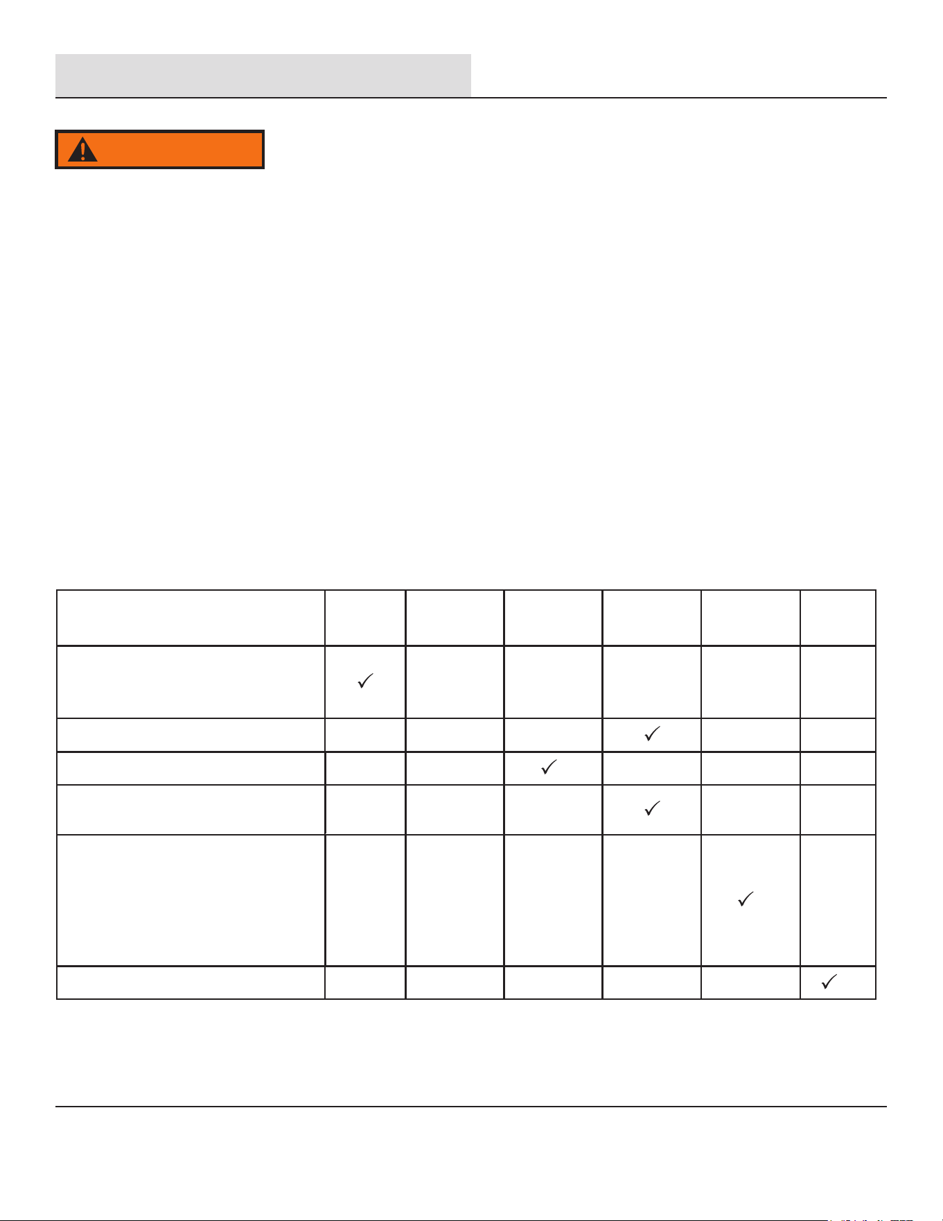
Cleaning, Maintenance, and Lubrication Schedule
Note: This maintenance schedule is intended as a general guide. If performance decreases or if equipment operates unusually, have the
generator inspected at once. The maintenance needs of generator will differ depending on factors such as duty-cycle, temperature, air
quality, fuel quality.
Note: The following procedures are in addition to the regular checks and maintenance explained as part of the regular generator.
WARNING
Procedure
Monthly or
every 8 hr.
of use
Replace fuel line if necessary
Before
Each Use
Every 3 mo.
or 50 hr.
of use
Every 6 mo.
or 100 hr.
of use
Every
2 Years
Yearly or
every 300 hr.
of use
1. Brush off outside of engine
2. Check engine oil level
3. Check air filter
Change engine oil
Clean/replace air cleaner
1. Check and clean spark plug
2. Check and clean spark arrestor
1. Check/adjust idle speed
2. Check/adjust valve clearance
3. Clean fuel tank, strainer
and carburetor
4. Clean carbon build-up from
combustion chamber
21
Maintenance
Checking and Filling Fuel
4. Add fuel, if needed.
5. Replace the Fuel Cap.
6. Wipe up any spilled fuel and allow excess to evaporate before
starting the engine. To prevent FIRE, do not start the engine
while the smell of fuel hangs in the air.
Engine Oil Change
1. Turn the generator off and allow the engine to cool for 30
minutes.
2. Place the generator on a level surface in a well-ventilated
area.
3. Place an oil drain pan under the generator and center it under
the oil drain opening.
4. Remove the oil drain plug from the generator, tilt the generator
slightly to facilitate drainage, and wait for the oil to drain
completely. Recycle used oil.
5. Clean the top of the oil fill and the area around it.
6. Add the appropriate type of oil until the oil level is at the proper
level. SAE 10
w-30 oil is recommended for general use.
Note: Make sure the generator is level when adding oil to prevent
overfilling which could cause engine damage.
7. Check engine oil level daily and add as needed. Remove and
clean the dipstick. Reinsert the dipstick but do not screw it back
in. Remove the dipstick and verify the oil is at the correct level.
8. When the engine oil is at the correct level, reinstall the dipstick
and screw it down until it is sealed. then, reinstall the right-side
panel.
TO PREVENT SERIOUS INJURY FROM FIRE: You must shut off
the engine and allow it to cool before refueling.
1. Clean the Fuel Cap and the area around it.
2. Unscrew and remove the Fuel Cap.
3. Remove the strainer and discard any dirt and debris, then
replace the strainer.
Note: Do not use gasoline that has been stored in a metal fuel
container or a dirty fuel container. It can cause particles to enter
the carburetor, affecting engine performance and/or causing
damage.
WARNING
Oil is very hot during operation and can cause burns. Wait for
the engine to cool before changing the oil.
CAUTION
• Do not attempt to run the generator with too little oil. The
engine will not start with low or no engine oil.
• Change the oil while the engine is warm but not hot. Warm
engine oil drains more quickly and thoroughly than cool oil.
Contact with hot oil will cause serious burns
NOTICE
Oil Fill & Dipstick
Oil drainage plug
Note: Do not use gasoline containing more than 10% ethanol
(E10). Do not use E85 ethanol. Add a fuel stabilizer ( such as
Sta-Bi or Pri-G ) to the gasline or the Warranty is VOID.
22
Maintenance
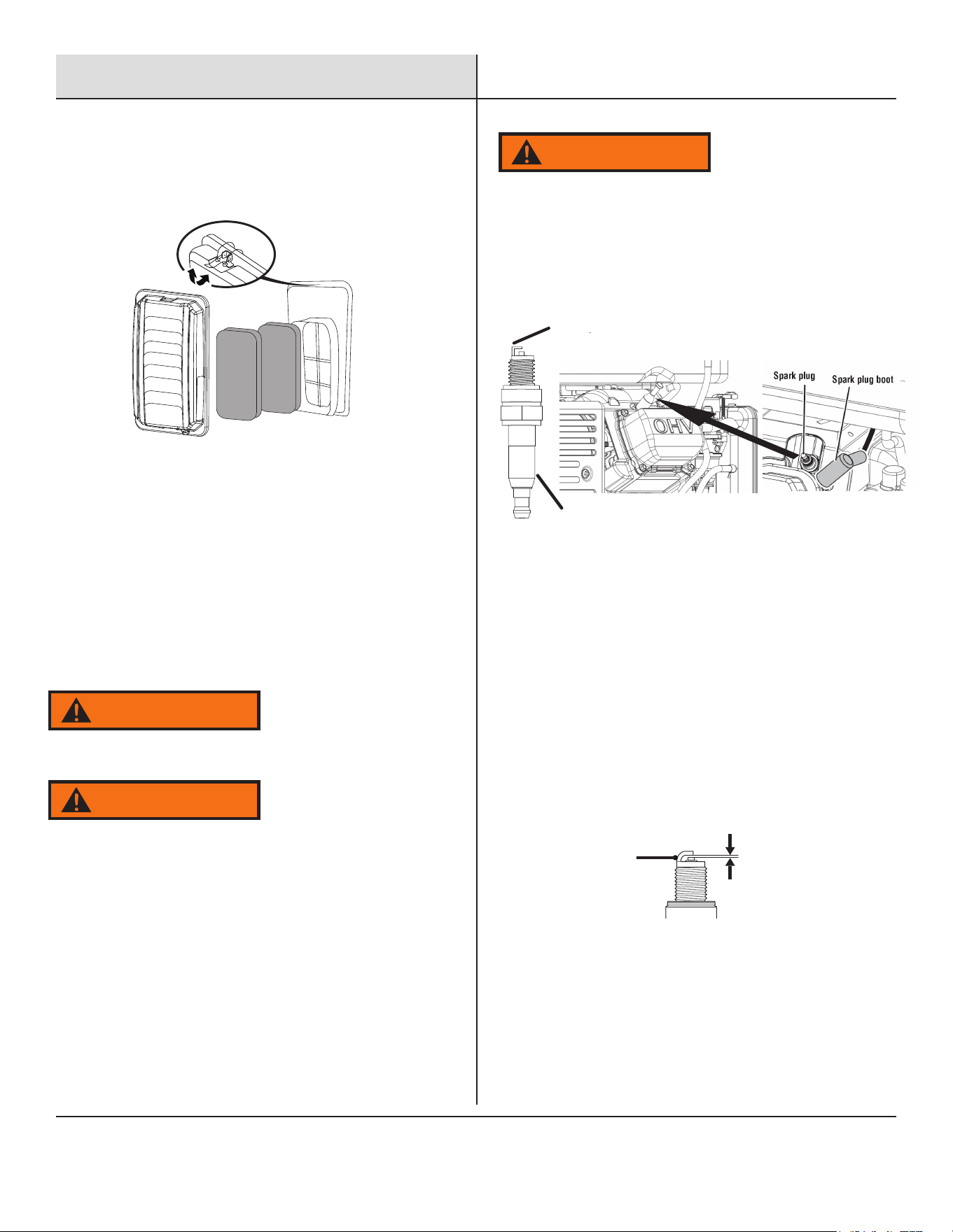
2. Remove tthe air filter element.
3. Wash the foam air filter element in hot, soapy water,
squeezing the solution though the foam until it is clean, rinse
the air filter element with clear water and dry it thoroughly
before reinstallation.
Spark Arrestor Maintenance
1. Inspect the spark arrestor for breaks or holes. Replace if
necessary. To purchase a replacement spark arrestor contact
PULSAR customer service.
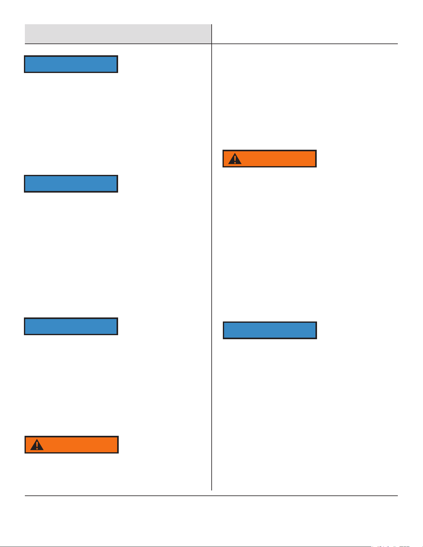
TO PREVENT SERIOUS INJURY AND FIRE:
2. Use an air compresseor (or vacuum cleaner), blow out any
debris from around the spark plug, then carefully remove the
spark plug boot from the plug.
3. Using the Spark Plug Wrench, unscrew and remove remove the
Spark Plug.
4. Inspect the Spark Plug: If the electrode is oily, clean it using a
clean, dry rag. If the electrode has deposits on it, clean it with a
brass wire brush. If the white insulator is cracked or chipped,
replace the spark plug.
5. Inspect and adjust the spark plug gap. (see below, Nte special
tools are required.)
6. If spark plug is worn replace only with an equivalent
replacement part. Spark plug should be replaced annually.
Operate only with proper spark arrestor installed
WARNING
The operation of this protective clothing and gloves may create
sparks that can start fires around dry vegetation. A spark
arrestor may be required. The operator should contact local
fire agencies for laws or regulations relating to fire prevention
requirements.
WARNING
TO PREVENT ACCIDENTAL BRUSH FIRE,secure spark arrestor
back in place immediately after cleaning and before further
operation.
Spark Plug Maintenance
1. Disconnect the spark plug wire from the spark plug.
WARNING
Air Filter Maintenance
1. To clean, Remove Air Filter Cover- see figure below.
2.Use a brush to remove carbon deposits from the spark
arrestor screen as needed.
3.To remove the spark arrestor: While the muffler is cool,
loosen the locking clamp and slide the spark arrestor out of the
muffler. Reverse this process to install it.
Insulator
Electrode
Spark plug gap: 0.024 – 0.032 in. (0.60 – 0.80 mm)
0.024 - 0.032 in.
(0.60 - 0.80 mm)
Side
Electrode
NOTE: Avoid contact with engine oil. Wear protective clothing
and safety glasses. Wash all exposed skin with soap and water.
Maintenance
• Hand-tighten until the gasket contacts the cylinder head, then
6 . When installing a new spark plug, adjust the electrode gap to
the specification on the Specifications Chart. Do not pry against
the center electrode, the spark plug can be damaged.
7 . Apply anti-seize material to Spark Plug threads. Install the
new spark plug or the cleaned spark plug into the engine.
tighten about 3/4 turn more.
7. Re-install the Spark Plug Access Cover.
Storage
When the generator is to remain idle for longer than 20 days,
prepare the engine for storage as follows:
1. CLEANING:
Wait for the engine to cool, open both side acess panels and blow
(or vacuum) any dirt or debris.
2. FUEL:
Gasoline Treatment/Draining the Fuel Tank
To protect the fuel tank during storage, fill the tank with fresh
gasoline that has been treated with a fuel stabilizer additive
(such as Sta-Bil, or Pri-G).
Follow fuel stabilizer manufacturer's recommendations for use.
Draining the Carburetor
Shut off gasoline flow by moving the fuel petcock under the tank,
place an appropriate container under the carburetor and carefully
remove the drain bolt from the bottom of the carburetor bowl,
allowing the fuel to drain completely. Replace the drain bolt after
draining.
Aged gasoline that has not been treated with stabilizer ahead of time
must be safely drained and disposed of, never run old gasoline
through the engine.
3. Extended storage:
a. Change engine oil.
b. Clean out the area around the spark plug. Remove the spark
plug and pour one tablespoon of engine oil into the cylinder
through the spark plug hole.
c. Replace spark plug, but leave spark plug boot.
d. Pull Recoil to distribute oil in the cylinder. Stop after one or
two revolutions when you feel the piston start the
compression stroke (when you start to feel resistance).
4. STORAGE AREA:
Cover and store in a dry, level, well-ventilated area out of reach
of children. The storage area should also be away from ignition
sources, such as water heaters, clothes dryers, and furnaces.
5. AFTER STORAGE:
Untreated gasoline will deteriorate quickly. Drain the fuel tank and
change to fresh fuel if untreated gasoline has been sitting for a
month, if treated gasoline has been stored beyond the fuel
stabilizer's recommended time, or if the engine does not start.
To prevent serious injury and fire, move the fuel petcock under the
tank to shut off gasoline supply before draining the carburetor.
WARNING
Fill the fuel tank in a well-ventilated area away from ignition
sources. If the engine is hot from use and wait for it to cool
before adding fuel. Do not smoke or vape anything.
WARNING
Use only BPR6ES (NGK) type spark plug or equivalent. Using
an incorrect spark plug may damage the engine.
NOTICE
Tighten the Spark Plug properly. If loose, the Spark Plug will
cause the engine to overheat. If overtightened, the threads in
the engine block will get damaged.
NOTICE
During extended storage periods, the engine should be started every
3 months and allowed to run for 15-20 minutes.
NOTICE
Do not clean using water. The water will gradually enter the
engine and cause damage.
NOTICE
23

Troubleshooting
24
Problem Cause Solution
Engine is running, but AC output is not
available
1. Op
en circuit breaker
2. Poor connection
3. Defective cord set
4. Connected device is faulty
5. Fault in generator
1. Reset circuit breaker
2. Check and repair
3. Check and repair
4. Connect a device that is working
properly
5. Contact service department
Engine runs well without load but bogs
down when
loads are connected
1. Short circuit in connected device
2. Generator is overloaded
3. Clogged fuel filter
4. Engine speed is too slow
5. Short circuit in generator
1. Disconnect device
2. See pg 17 “Don’t overload
generator”
3. Clean or replace fuel filter
4. Contact service department
5. Contact service department
Engine will not start, shuts down during
operation, or starts and runs rough.
1.
RUN/STOP switch set to “STOP”
2.
Dirty Air filter
3.
Clogged fuel filter
4.
Stale fuel
5.
Spark plug wire disconnected from
spark plug
6.
Bad spark plug
7.
Water in fuel
8.
Fuel valve is in “OFF” position
9.
Over choking
10.
Low oil level
11.
Rich fuel mixture
12.
Intake valve stuck open or closed
13.
Loss of engine compression
14.
Engine has flooded
15.
CO Sensor indicator light turn red
16.
CO Sensor indicator light turn
yellow
1.
Turn switch to “RUN”
2.
Replace Air filter
3.
Clean or replace fuel filter
4.
Replace fuel
5.
Reconnect spark plug wire
6.
Replace spark plug
7.
Drain fuel tank and replace fuel
8.
Turn fuel valve to “ON” position
9.
Turn off choke
10.
Fill crankcase to proper oil level &
place generator on a level surface
11.
Contact service department
12.
Contact service department
13.
Contact service department
14.
Wait 5 minutes and crank engine
15.
Move the generator to an open,
outdoor area
16.
Contact service department
Engine lacks power 1. Generator is overloaded
2. Clogged fuel filter
3. Dirty Air filter
4. Engine needs servicing
1.
See pg. 17 “Don’t overload
generator”
2.
Clean or replace fuel filter
3.
Replace Air filter
4.
Contact service department
Engine “hunts” or falters
1.
Choke was opened too soon
2.
Clogged fuel filter
3.
Carburetor is running too rich or too
lean
1.
Move choke to middle position until
engine runs smoothly
2.
Clean or replace fuel filter
3.
Contact service department