OPERATOR’S MANUAL
Warning: The Engine Exhaust from this product contains chemicals known to the
State of California to cause cancer, birth defects or other reproductive harm.
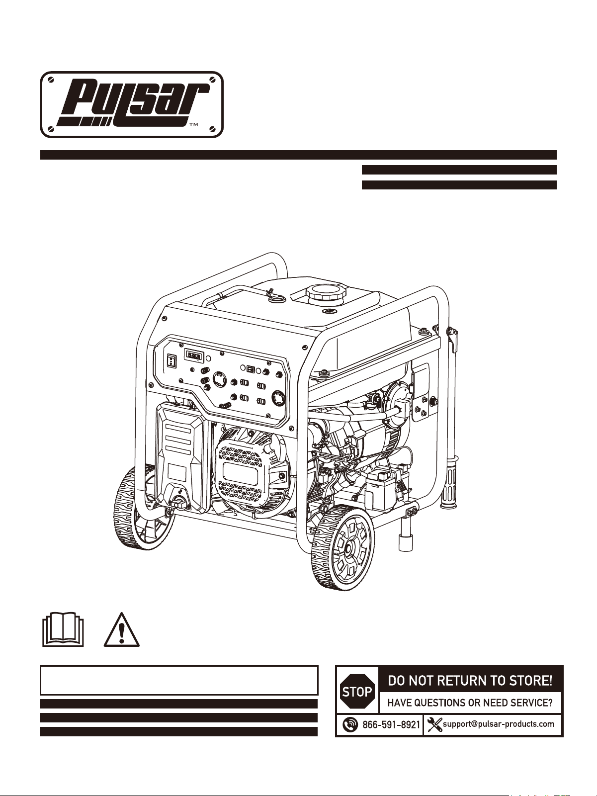
9000 WATT GENERATOR
Model NO. PGL9000BCO

1
Table of Contents
Table of Contents ………………….………………...….1
I n s t r u c t i o n s … … … … … … … . … … . … … … … … … … . 1
Safety Warnings and Notices ………….……………...….1
Safety Instructions………………….……………….……2
Connecting Propane … … … … … … … … ……… … … … .12
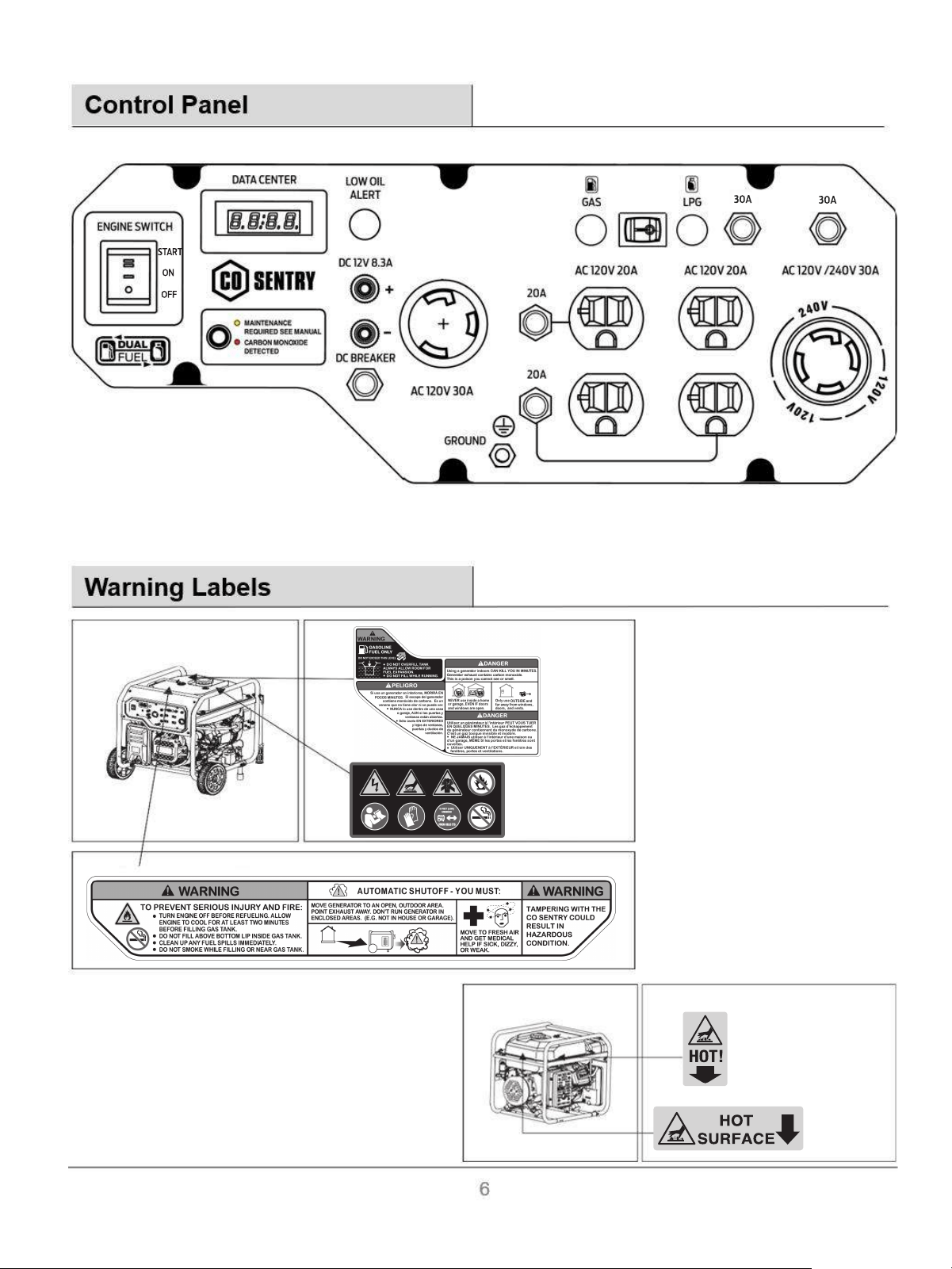
Co n tr o l P a n el ……… … … … … … …… … .… …… …… … 6
Warning La b e l s
…… …… … … … … …… …. …… …… … … 6
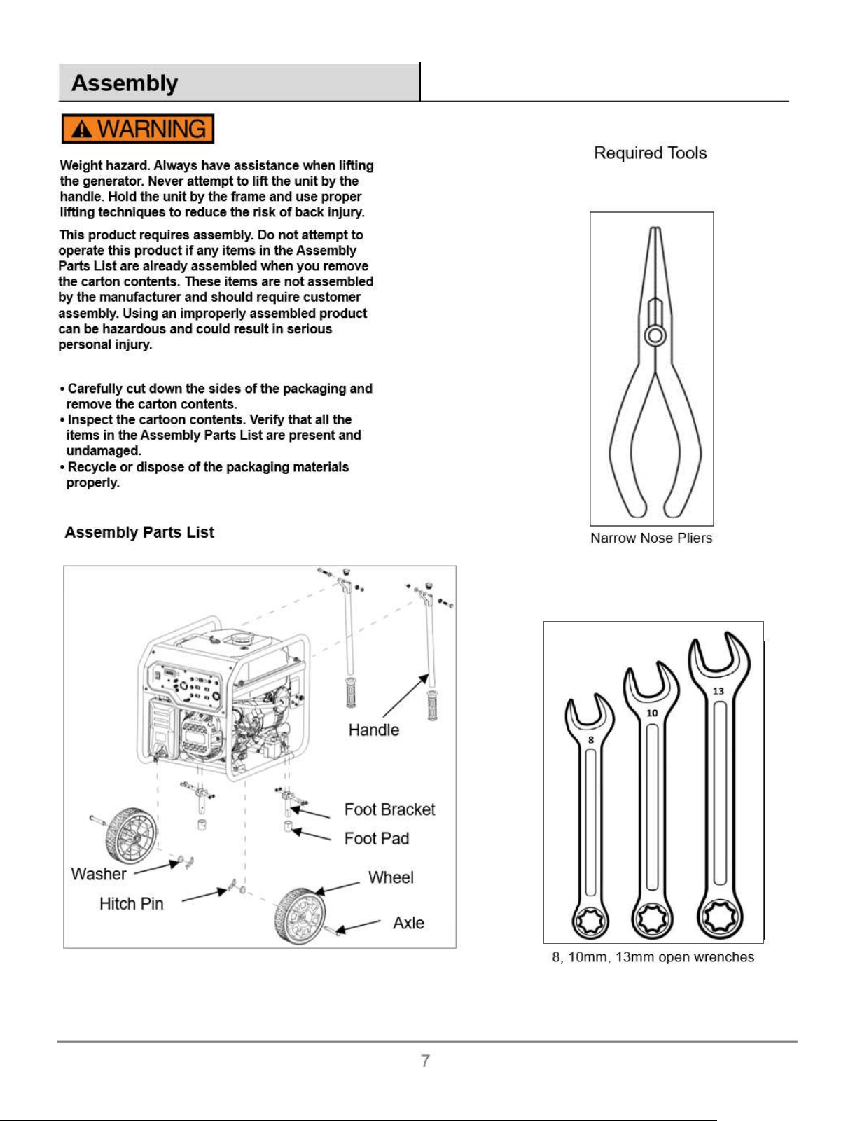
Ass em bl y…………………………………………………… .7
Safety Mandates……………………………………………
10
General Safety - Best Practices ………………………
11
Fuel Selection ………………........………………................13
Engine Start - Electric ………….......................................14
Add Gasoline ……………………………….………….….....12
Engine Start - Recoil(Pull) …………
……….……….…....15
Using Electrical Power …………………...........................16
Generator Shutdown ….................................................17
Long Term Storage …………………………….............18
Specifications ………………………….........................19
Component Locator –PGL9000BCO …………………………20
Electrical Schematic…………………….…………….….21
Introduction
Thank you for choosing Pulsar Products!
This manual provides instruction on how to operate
and use your generator safely and correctly; be sure to
read and understand this manual before using your
generator. If you have ANY questions, please phone
866.591.8921 M-F or support@pulsar-products.com
BEFORE using your generator.
All details and images in this User's Manual are
believed to be accurate at the time of publication.
Pulsar Products reserves the right to make updates to
this manual at any
time.
Please contact Pulsar Support at 8
66.591.8921 or
s
upport@pulsar-products.com for the latest
updates.
This manual is a permanent part of the generator set. If
the generator is resold, kindly include this manual with
the generator.
Safety Warnings and Notices
WARNING: Save This Manual For
Future Reference
This manual contains important information regarding
the safety, operation, maintenance, and storage of this
product. Before use, read carefully and understand all
cautions, warnings, instructions, and product labels.
Failure to do so could result in serious personal injury
and/or property damage.
2
Burn Hazard. DO NOT touch
hot surfaces
Read Manufacturer’s
Instructions
Ground. Consult with
electrician to determine
grounding requirements
before use
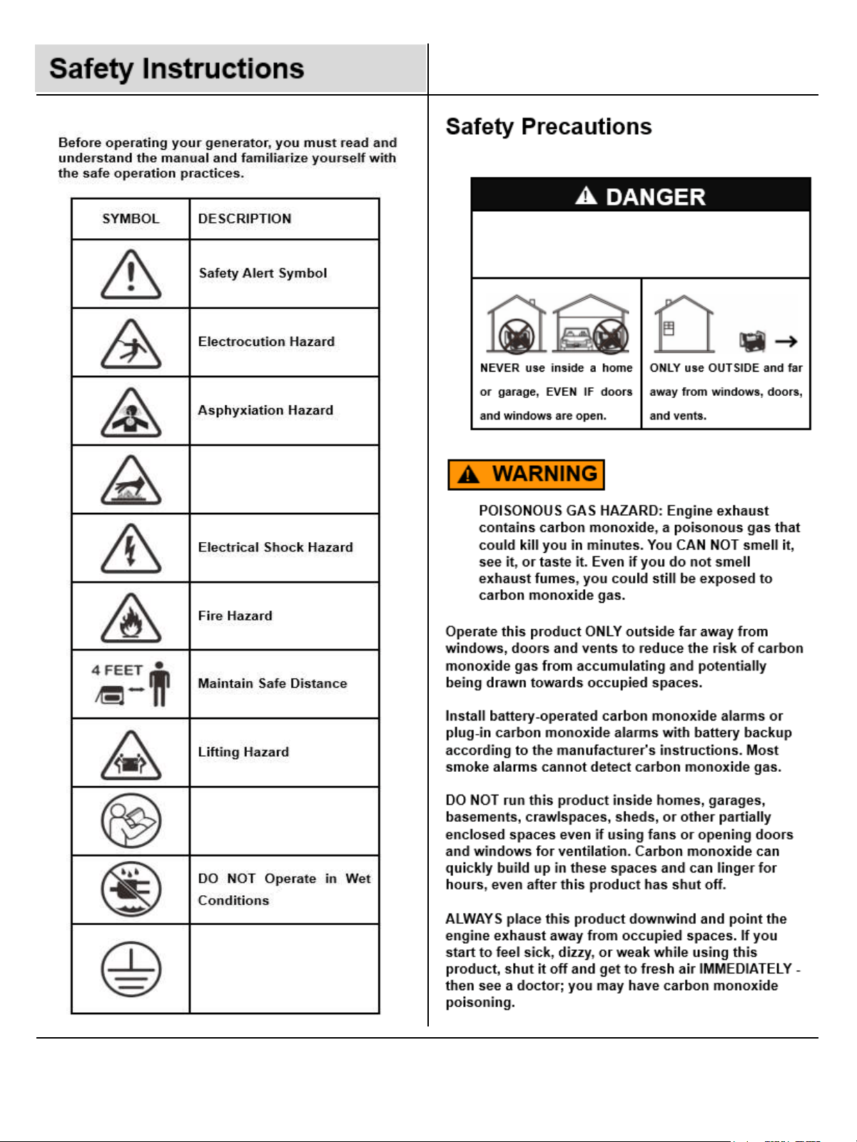
Using an engine indoors CAN KILL YOU IN MINUTES.
Generator exhaust contains carbon monoxide.This is a
poison you cannot see or smell.

3
can


5
Safety Instructions
1. Remove and immediately recycle or dispose of used batteries according to local regulations and keep
away from children. Do NOT dispose of batteries in household trash or incinerate.
2. Even used batteries may cause severe injury or death.
3. Call a local poison control center for treatment information.
4. The voltage of battery CR2032 is usually 3V or 3.1V, for more information, please check the generator
manual or dealer.
5. Non-rechargeable batteries are not to be recharged.
6. Do not force discharge, recharge, disassemble, heat above 60℃(140℉) or incinerate. Doing so may
result in injury due to venting, leakage or explosion resulting in chemical burns.
NOTE: THIS PRODUCT CONTAINS NON-REPLACEABLE BATTERIES

8
Do not alter or modify this product unless instructed to
so in this manual or by the manufacturer. Do not use
attachments or accessories that are not recommended
for use with this product. Making unauthorized
modifications and using incompatible accessories can
damage the unit and void your warranty.
Pinch point hazard. Do not place your hand or fingers
between the handle and the generator's frame.
M6 Nut ×4
Used for Support
Leg
• Parts needed-Handle & M8 screw (2) and 2 nuts
9
• Position the handle and bolts.
• Align the holes on the handle with the holes on the
downtube.
• Thread the bolt through the hole on the handle and
the hole on the downtube.
• Tighten nuts securely. Do not over tighten.
• Repeat these steps to install second handle.
Installing the Handle (cont.)
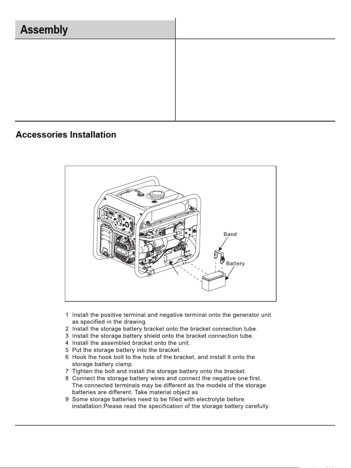
Some models feature an Electric Start option, which require assembly of a battery bracket and band.
Battery Bracket
10
Safety Mandates
11
Operator should wear personal protection suitable for
the environment and task. Example: Heat resistant
gloves, hearing protection and safety glasses when
operating or maintaining the generator.
Do not attempt major repairs or internal work on the
generator. Leave this job to a qualified repair shop or
a Pulsar authorized service center.
Never operate any generator underground or in any
kind of enclosed, explosive or IDLH (Immediately
Dangerous to Life and Health) environment.
This generator makes enough electrical power to
cause serious shock or electrocution if misused.
Never touch any exposed wires or operate any
generator with wet hands.
Always keep children and pets away from any
generator whether it is running or not.
Always use an inline GFCI (Ground Fault Circuit
Interrupter) when connected loads operate in a damp
location.
Always shut down the generator and allow it to cool
completely before attempting any adjustments,
maintenance or repair.
Never add fuel while the generator is running!
Immediately wipe up any spilled gasoline with a cloth
rag or paper towel, but do NOT place it in a trash can
until it is completely dry.
Never connect in series (Daisy Chain) electrical extension cords! You must consult
a Wire Gauge Calculator to determine the appropriately sized cable cross-section
for your specific use case, load profile, and run distance.
Do NOT attempt to connect in parallel any different model of generator. Use only
Pulsar approved parallel kits with generators that are certified to work together.
You MUST maintain a minimum distance of 6 feet (2
meters) between the generator and any structure or
other flammable materials
Only dispose of oil or gasoline in accordance with
your municipal recycling or waste management
program, NEVER place it in the trash for collection!
Never place any heavy items on top of the generator.
Only dispose of oil or gasoline in accordance with
your municipal recycling or waste management
program, NEVER place it in the trash for collection!
During operation this generator has many fast moving and rotating parts. Always
contain long hair, loose jewelry and clothing before approaching a generator
For maximum service life, do not run the generator in excess of it’s rated output and
always maintain the equipment per manufacturers recommendations.
The wheels and handles provided with the unit are for convenience of placement,
never attempt to tow the generator or cover long distances with this equipment.
ALWAYS remain aware of wind direction and take great care to point the generator
exhaust flow AWAY from any structure or occupied space. Keeping a minimum
distance of 6 feet from any flammable object is recommended
12
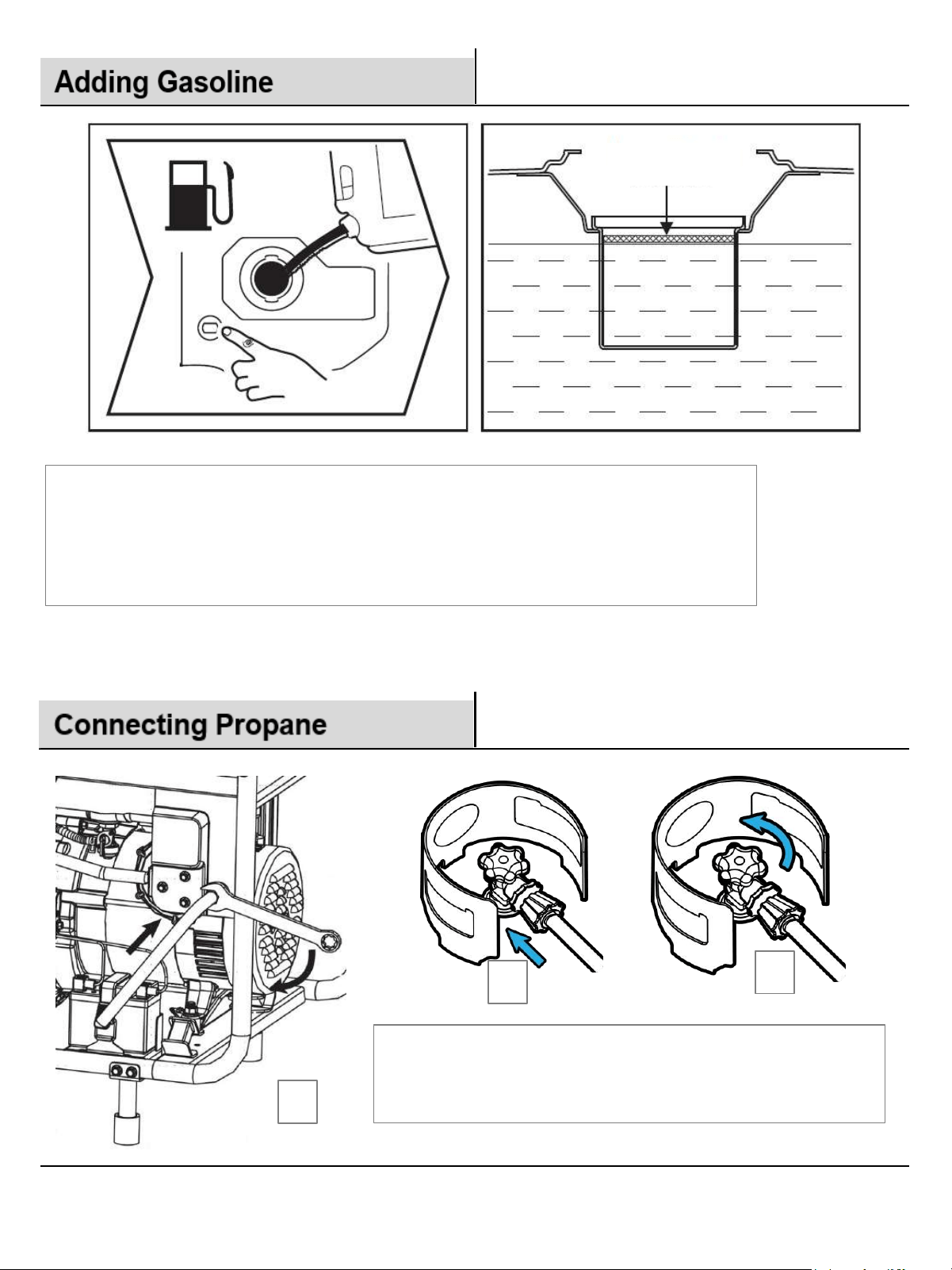
1. Never unscrew a fuel cap or attempt to refuel a running generator!
2. Unscrew and remove the fuel tank cap and set it aside.
3. Keep away all ignition sources and never smoke anything while fueling a generator!
4. Add FRESH GASOLINE ONLY to the fuel tank until it is filled to the desired level.
5. Do NOT fill gasoline beyond the Full Mark in the illustration above
6. Note there is a float-type fuel gauge, for your convenience per illustration above
Full Mark
3
2
1. Thread propane supply hose onto the generator male
fitting and snug it with a wrench. Do not overtighten!
2. Attach regulator hose to propane supply tighten by hand.
3. Open propane supply valve and check for leaks.
1
, left.
,right.
13
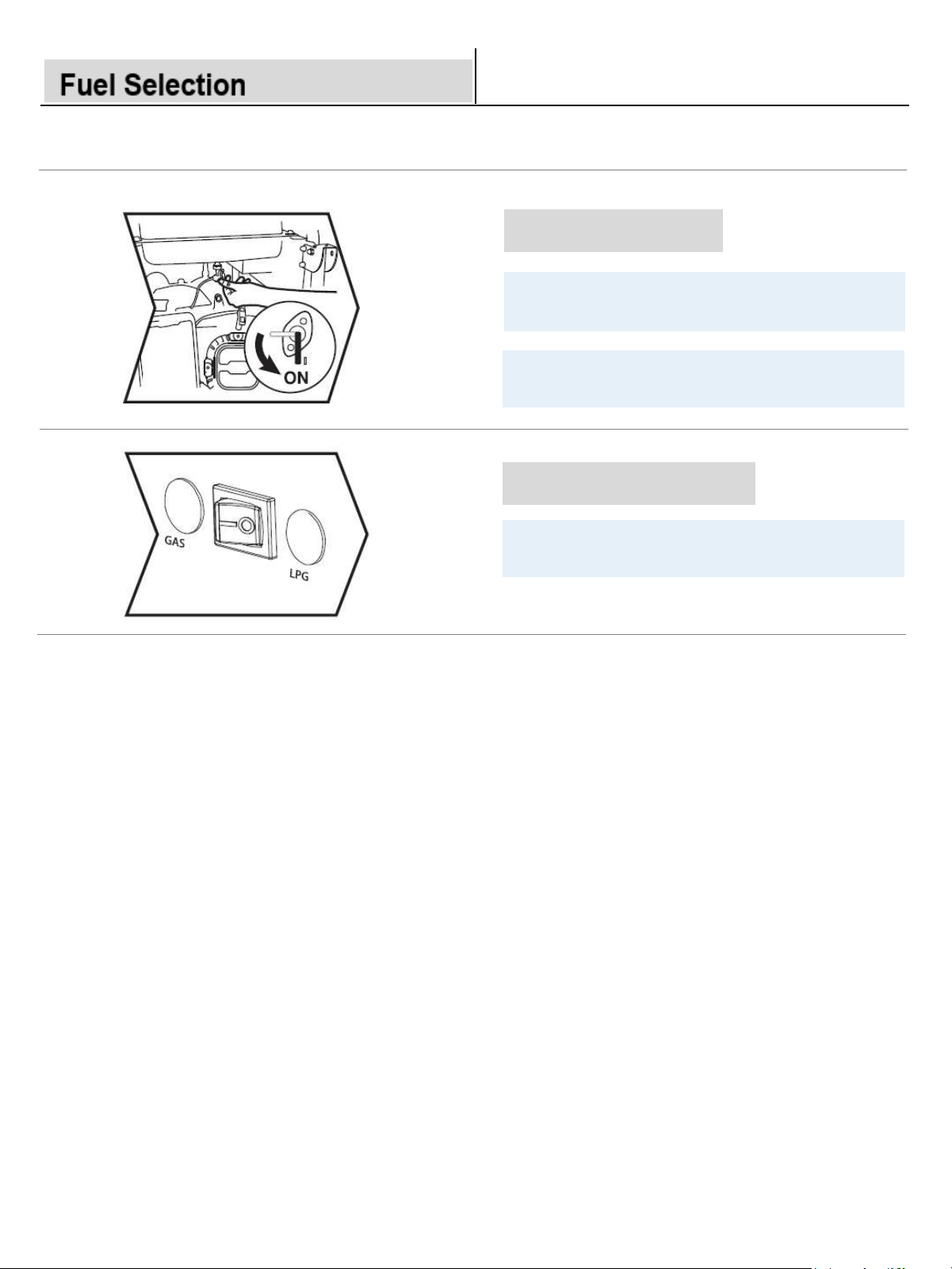
Gasoline Petcock
Move to ‘ON’ if you intend to run the
generator on gasoline.
Keep the petcock closed if you intend to run
the generator on propane.
Fuel Selector Switch
Move this switch to your desired fuel source
GAS = Gasoline LPG - Propane.
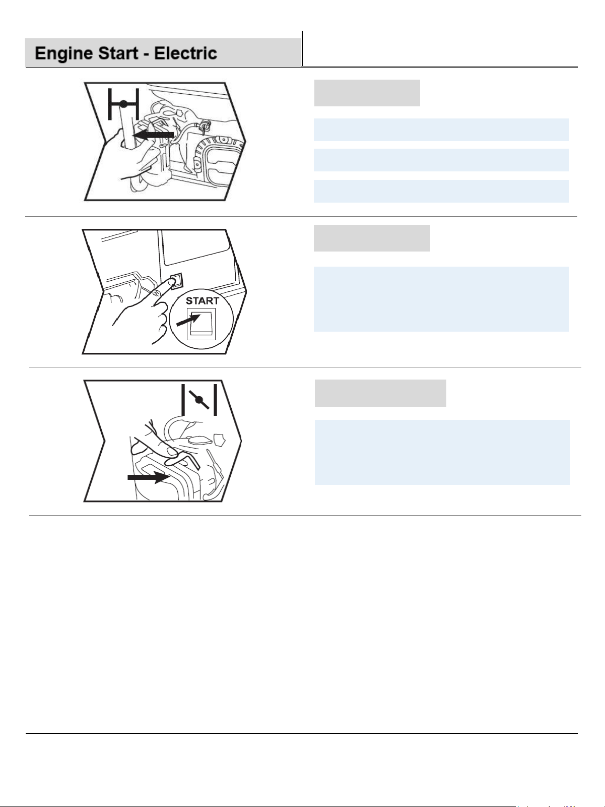
Choke Lever
Cold Engine – Move the lever left for starting.
Warm Engine – Partial choke for starting.
Running Engine – Move the lever full right.
Engine Switch
Press and hold the engine switch in the
START position to crank the engine for a few
seconds, or until the engine starts, then
release the switch.
Open the Choke
After a successful engine start, gradually
open the choke by moving the choke lever to
the right until it is fully open. You may need to
do this slowly in very cold weather.
14
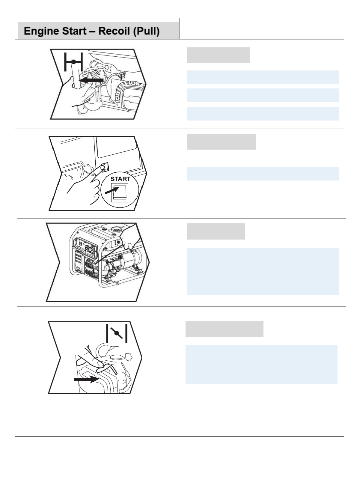
Choke Lever
Cold Engine – Move the lever left for starting.
Warm Engine – Partial choke for starting.
Running Engine – Move the lever full right.
Engine Switch
Move the engine switch to the ‘ON’ position.
With a firm, stable footing, grasp the recoil
handle and pull it out until resistance is felt.
Let the rope retract, then pull it swiftly and
fully. Repeat this step as necessary until the
engine starts.
Recoil Start
Open the Choke
After a successful engine start, gradually
open the choke by moving the choke lever to
the right until it is fully open. You may need to
do this slowly in very cold weather.
15
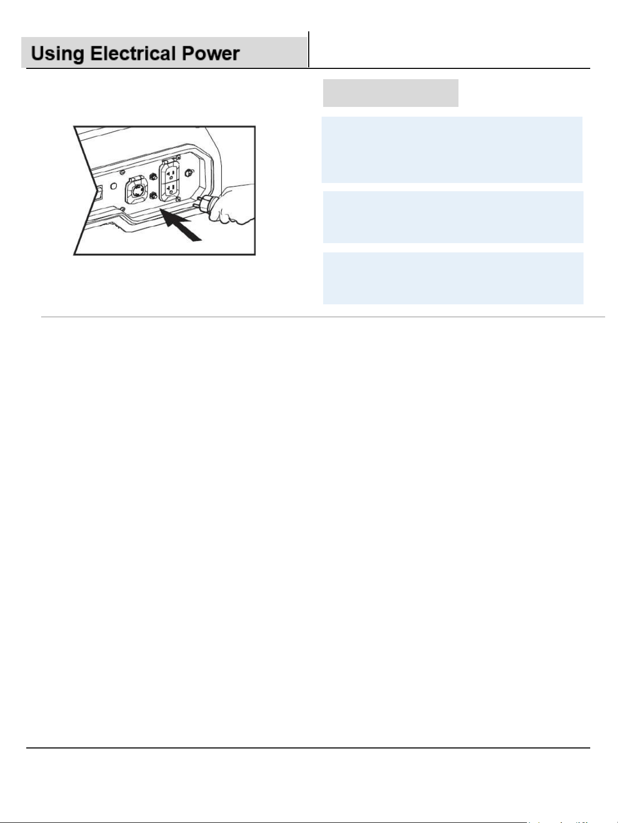
Connect Load(s)
Allow the engine to warm up for at least 30
seconds, then attach your loads from
smallest to largest, allowing the generator to
stabilize between each load applied.
Take care not to exceed the load limits of the
generator, especially with inductive loads
such as motors.
Power output is based upon sea level, +15C,
and 30% RH. Changes in elevation and
weather can reduce the generator capacity.
16
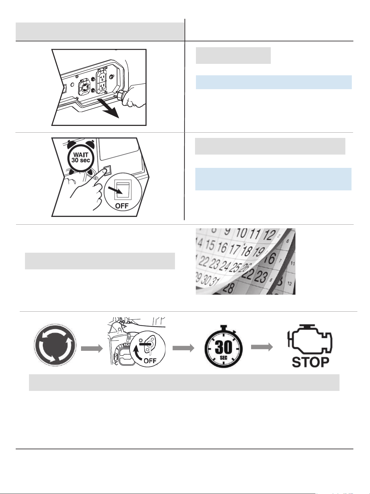
Remove Loads
Switch off then unplug all connected devices.
Remove all loads, wait 30 seconds, then
move the Engine Switch to ‘OFF .’
To Store the Generator <30 days
To Store the Generator >30 days
Engine running Close the petcock Fuel is consumed Engine stop
17
Generator Shutdown
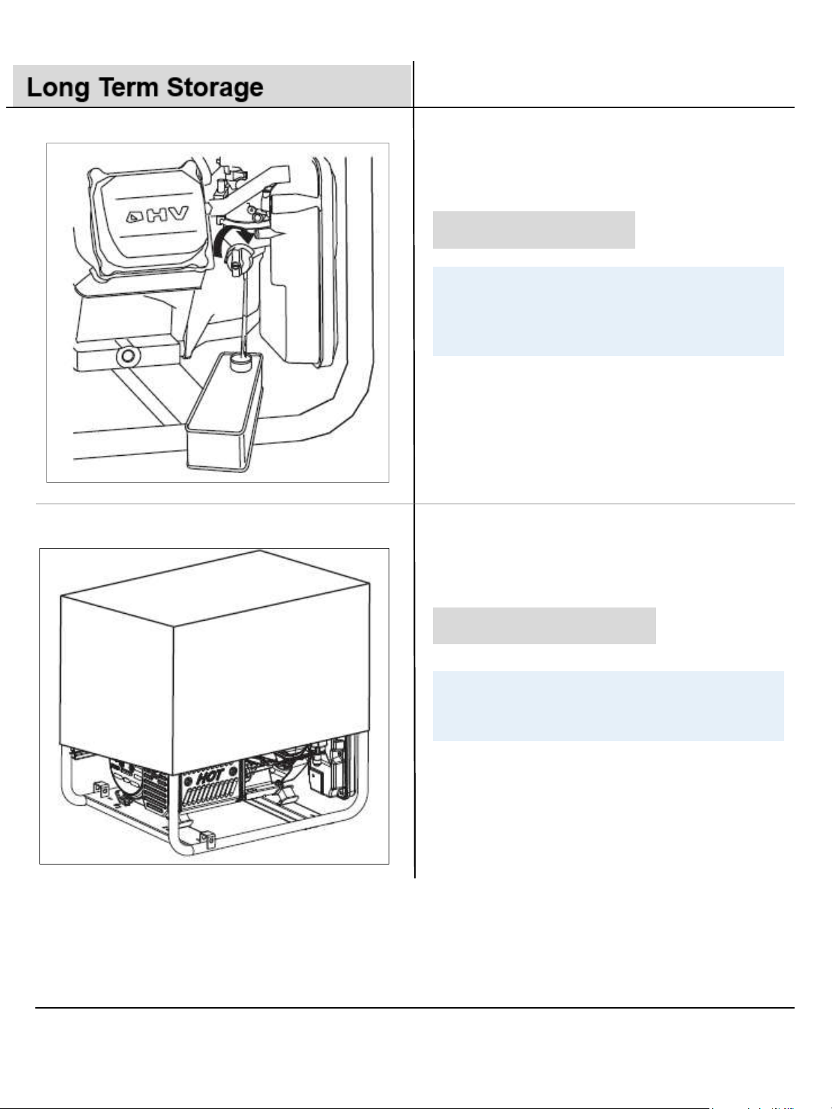
Drain the Gasoline
With the gasoline petcock OFF you may
place a suitable container under the
carburetor, remove the drain plug and collect
remaining gasoline from the float bowl.
Elemental Protection
For long term storage a suitable weather
protective cover should be used to protect
your generator from rain, dirt, and debris.
18

Specifications
Igniting Mode
T.C.I.
Model
Starting mode
Capacity of
fuel tank
AC o utput
Frequency
Voltage
60Hz
Type
RPM
Fuel
Engine oil capacity
Spark plug type
Spark Plug Gap
E ngine
Single cylinder forced air cooling 4 strokes
Gasoline / LPG
F7TC F7RTC N9YC RN9YC
Valve clearance
(Intake/Exhaust)
Displacement
Weight (only for reference)
Overall dimens ions ( excluding packing box)
7 gallons
24.5x19.5x22 inches
Recoil start / Electric start
3600 r/min
PGL9000B C O
120V/240V
340cc
134 lbs. 143 lbs. ( ) ( )Recoil start Electric start
0.9 L
0
7-0.8 mm
L x W x H (mm)
Net weight( )kg
0
05-0 10 mm / 0.10-0.15mm
Rated Power
(GAS/LPG)
Peak Power
(GAS/LPG)
7.2/6.5 kW
9.0/8.1 kW
19
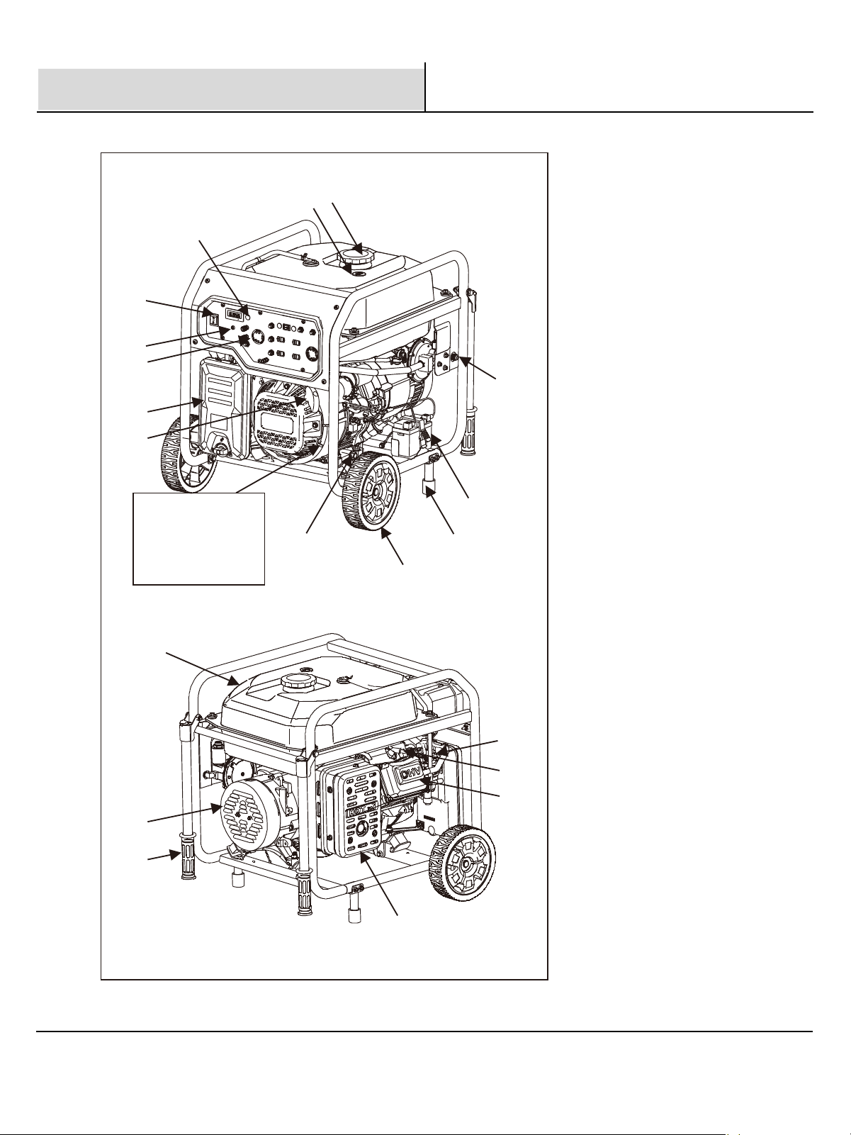
Component Locator –PGL9000BCO
5
4
3
6
7
8
9
Serial number
T*****YYMM*******
The YYMM is year
and month of
manufactured.
10
11
12
2
1
15
16
18
19
20
13
14
1
2
3 Low oil alert
4 Engine switch
5 CO protect
6 AC output
7 Air filter
8 Recoil starter
9 Oil drain
10 Wheel
11 Foot
12 Battery (optional)
13 LPG hose connector
14 Fuel tank
15 Cover, Generator End
16 Handle
17 Muffler
18 Cylinder head
19 Spark plug
20 Carburetor
Fuel tank cap
Fuel gauge
17
20
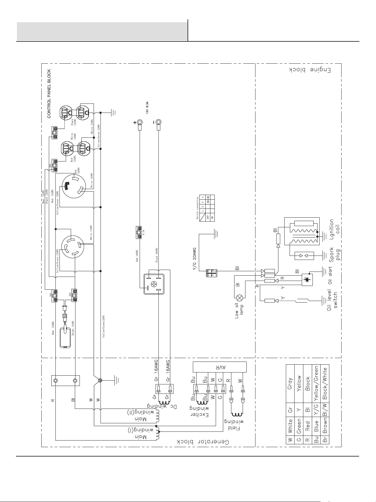
Electrical schematic
Recoil start
21
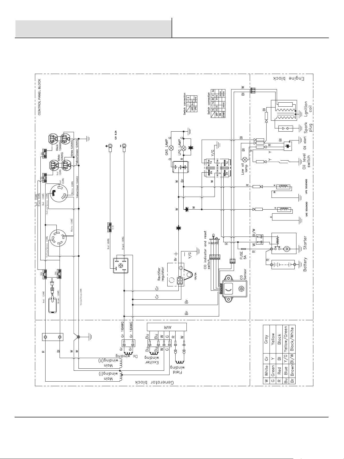
Electrical schematic
Electric start
22