Home
Bookmarks
Home
FLUKE
FLUKE 190-504/UN/S User Manual
Page 2
FLUKE 190-504/UN/S ScopeMeter Test Tool, 500MHz, SCC
User Manual for the Fluke 190-504/UN/S ScopeMeter Test Tool, 500MHz, SCC - Page 2
For 190-504/UN/S.
PDF File Manual
,
146 pages
,
Read Online
|
Download pdf file
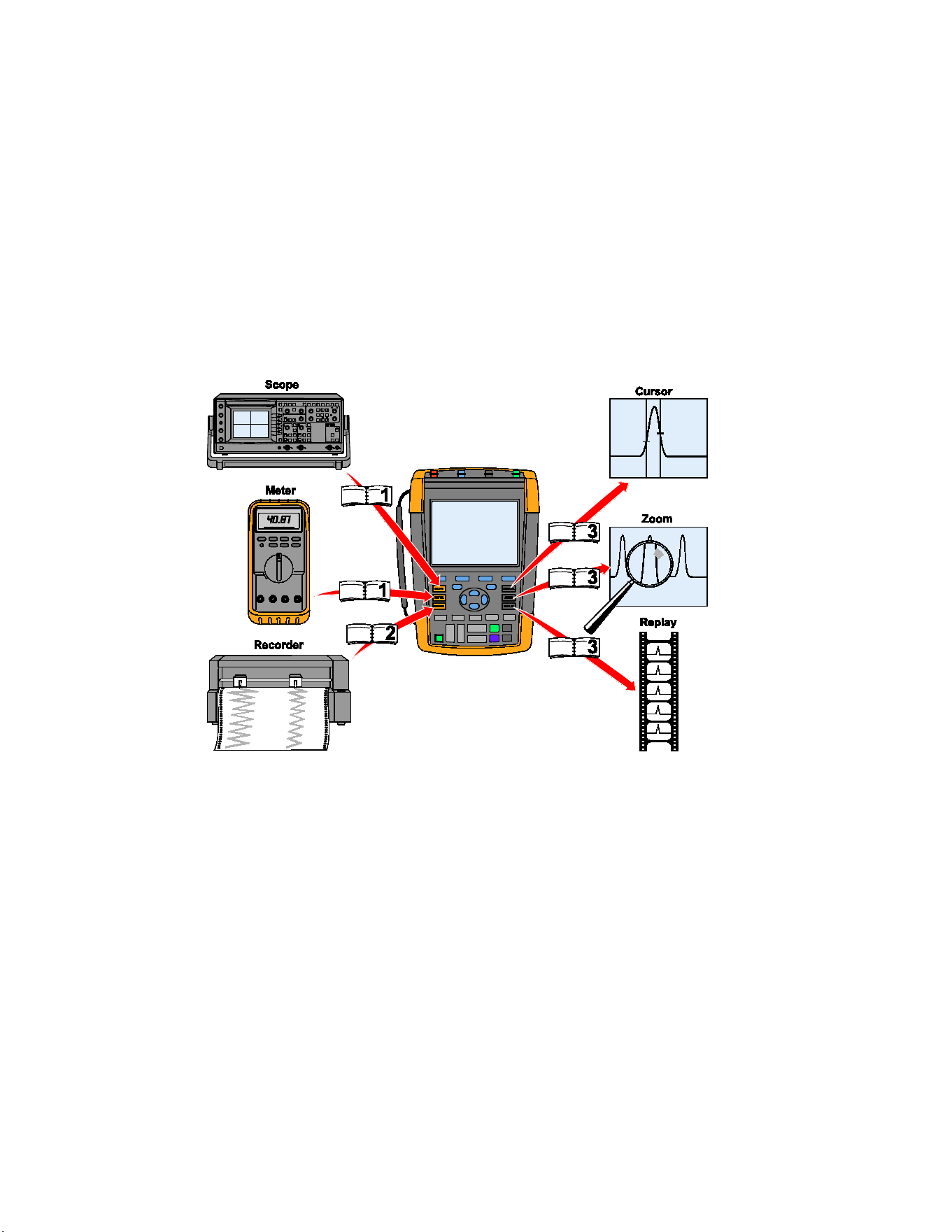
ScopeMeter® Test Tool 190 Series II Users Manual
LIMITED WARRANTY & LIMITATION OF LIABILITY
Table of Contents
Safety
Introduction
Unpacking the Test Tool Kit
Safety Information: Read First
Safe Use of Li-ion battery pack
1. Using the Scope and Meter
Chapter 1
Powering the Test Tool
Resetting the Test Tool
Navigating a Menu
Hiding Key Labels and Menus
Key Illumination
Input Connections
Making Input Connections
Adjusting the Probe Type Settings
Selecting an Input Channel
Displaying an Unknown Signal with Connect-and-View™
Making Automatic Scope Measurements
Freezing the Screen
Using Average, Persistence and Glitch Capture
Using Average for Smoothing Waveforms
Smart average
Using Persistence, Envelope and Dot-Join to Display Waveforms
Displaying Glitches
Suppressing High Frequency Noise
Acquiring Waveforms
Setting the Acquisition Speed and Waveform Memory Depth
Selecting AC-Coupling
Reversing the Polarity of the Displayed Waveform
Variable Input Sensitivity
Working with Noisy Waveforms
Using Mathematics Functions +, -, x, XY-mode
Using Mathematics Function Spectrum (FFT)
Comparing Waveforms
Pass - Fail Testing
Analyzing Waveforms
Making Automatic Meter Measurements (for models 190-xx4)
Selecting a Meter Measurement
Making Relative Meter Measurements
Making Multimeter Measurements (for models 190-xx2)
Making Meter Connections
Measuring Resistance Values
Making a Current Measurement
Selecting Auto/Manual Ranges
Making Relative Meter Measurements
2. Using The Recorder Functions
Opening the Recorder Main Menu
Plotting Measurements Over Time (TrendPlot™)
Starting a TrendPlot Function
Displaying Recorded Data
Changing the Recorder Options
Turning Off the TrendPlot Display
Recording Scope Waveforms In Deep Memory (Scope Record)
Starting a Scope Record Function
Displaying Recorded Data
Using Scope Record in Single Sweep Mode
Using Triggering to Start or Stop Scope Record
Analyzing a TrendPlot or Scope Record
3. Using Replay, Zoom and Cursors
Replaying the 100 Most Recent Scope Screens
Replaying Step-by-Step
Replaying Continuously
Turning Off the Replay Function
Capturing 100 Intermittents Automatically
Zooming in on a Waveform
Turning Off the Zoom Function
Making Cursor Measurements
Using Horizontal Cursors on a Waveform
Using Vertical Cursors on a Waveform
Using Cursors on a Mathematical Result (+ - x) Waveform
Using Cursors on Spectrum Measurements
Making Rise Time Measurements
4. Triggering on Waveforms
Setting Trigger Level and Slope
Using Trigger Delay or Pre-trigger
Automatic Trigger Options
Triggering on Edges
Triggering on Noisy Waveforms
Making a Single Acquisition
N-Cycle Triggering
Triggering on External Waveforms (models 190-xx2)
Triggering on Video Signals
Triggering on Video Frames
Triggering on Video Lines
Triggering on Pulses
Detecting Narrow Pulses
Finding Missing Pulses
5. Using Memory and PC
About this Chapter
Using the USB Ports
Saving and Recalling
Saving Screens with Associated Setups
Saving Screens in .bmp Format (Print Screen)
Deleting Screens with Associated Setups
Recalling Screens with Associated Setups
Recalling a Setup Configuration
Viewing Stored Screens
Renaming Stored Screens and Setup Files
Copying-Moving Stored Screens and Setup Files
Using FlukeView®
Connecting to a Computer
6. Tips
About this Chapter
Using the Standard Accessories
Using the Independently Floating Isolated Inputs
Measuring Using Independently Floating Isolated Inputs
Using the Tilt Stand
Kensington®-lock
Fixing the Hangstrap
Resetting the Test Tool
Suppressing Key Labels and Menu’s
Changing the Information Language
Adjusting the Contrast and Brightness
Changing Date and Time
Saving Battery Life
Setting the Power Down Timer
Setting the Display AUTO-off Timer
Changing the Auto Set Options
7. Maintaining the Test Tool
Cleaning the Test Tool
Storing the Test Tool
Charging the Batteries
Replacing the Battery Pack
Calibrating the Voltage Probes
Displaying Version and Calibration Information
Displaying Battery Information
Parts and Accessories
Replacement Parts
Optional Accessories
Troubleshooting
The Test Tool Shuts Down After a Short Time
The Screen Remains Black
The Test Tool Cannot Be Turned Off
FlukeView® Does Not Recognize The Test Tool
Battery Operated Fluke Accessories Do Not Function
8. Specifications
Introduction
Oscilloscope
Isolated Inputs A,B, C and D (Vertical)
Horizontal
Trigger and Delay
Automatic Connect-and-View Trigger
Edge Trigger
Isolated External Trigger (190-xx2)
Video Trigger
Pulse Width Trigger
Continuous Auto Set
Automatic Capturing Scope Screens
Automatic Scope Measurements
General
DC Voltage (VDC)
AC Voltage (VAC)
AC+DC Voltage (True RMS)
Amperes (AMP)
Peak
Frequency (Hz)
Duty Cycle (DUTY)
Pulse Width (PULSE)
Vpwm
V/Hz
Power (A and B, C and D)
Phase (A and B, C and D)
Temperature (TEMP)
Decibel (dB)
Meter Measurements for Fluke 190-xx4
Meter Measurements for Fluke 190-xx2
Meter Input (Banana Jacks)
Meter Functions
General
Ohms (()
Continuity (CONT)
Diode
Temperature (TEMP)
DC Voltage (VDC)
AC Voltage (VAC)
AC+DC Voltage (True RMS)
Amperes (AMP)
Recorder
TrendPlot (Meter or Scope)
Scope Record
Zoom, Replay and Cursors
Zoom
Replay
Cursor Measurements
Miscellaneous
Display
Power
Probe Calibration
Internal Memory
External Memory
Mechanical
Interface Ports
Environmental
Standards
Safety
10:1 Probe VPS410
Accuracy
Electromagnetic Immunity
Appendices
A. Installing USB Drivers
Introduction
Installing the USB Drivers
B. Battery Pack MSDS
Li-ion Battery Pack
Page 2/146
Page 1
Page 2
Page 3
Page 4
Page 5
Page 6
Page 7
Page 8
Page 9
Page 10
Page 11
Page 12
Page 13
Page 14
Page 15
Page 16
Page 17
Page 18
Page 19
Page 20
Page 21
Page 22
Page 23
Page 24
Page 25
Page 26
Page 27
Page 28
Page 29
Page 30
Page 31
Page 32
Page 33
Page 34
Page 35
Page 36
Page 37
Page 38
Page 39
Page 40
Page 41
Page 42
Page 43
Page 44
Page 45
Page 46
Page 47
Page 48
Page 49
Page 50
Page 51
Page 52
Page 53
Page 54
Page 55
Page 56
Page 57
Page 58
Page 59
Page 60
Page 61
Page 62
Page 63
Page 64
Page 65
Page 66
Page 67
Page 68
Page 69
Page 70
Page 71
Page 72
Page 73
Page 74
Page 75
Page 76
Page 77
Page 78
Page 79
Page 80
Page 81
Page 82
Page 83
Page 84
Page 85
Page 86
Page 87
Page 88
Page 89
Page 90
Page 91
Page 92
Page 93
Page 94
Page 95
Page 96
Page 97
Page 98
Page 99
Page 100
Page 101
Page 102
Page 103
Page 104
Page 105
Page 106
Page 107
Page 108
Page 109
Page 110
Page 111
Page 112
Page 113
Page 114
Page 115
Page 116
Page 117
Page 118
Page 119
Page 120
Page 121
Page 122
Page 123
Page 124
Page 125
Page 126
Page 127
Page 128
Page 129
Page 130
Page 131
Page 132
Page 133
Page 134
Page 135
Page 136
Page 137
Page 138
Page 139
Page 140
Page 141
Page 142
Page 143
Page 144
Page 145
Page 146
Contents
Table of Contents
Search
Previous
Next
Troubleshooting
Bookmarks
Loading ...
hpp00.eps
1.888.610.7664
sales@GlobalT
estSupply
.com
Fluk
e
-
D
ir
ect
.com
Loading ...
Loading ...
Loading ...
File type: PDF
File name: 87280116_190-504-un-s.pdf
File size: 4.04 MB
File Language: English
Pages: 146
Author: FLUKE
Published: 2024-02-09
Updated: 2024-02-09
Download File
Table of Contents
×
ScopeMeter® Test Tool 190 Series II Users Manual
1
LIMITED WARRANTY & LIMITATION OF LIABILITY
3
Table of Contents
4
Safety
12
Introduction
12
Unpacking the Test Tool Kit
13
Safety Information: Read First
15
Safe Use of Li-ion battery pack
19
1. Using the Scope and Meter
22
Chapter 1
22
Powering the Test Tool
22
Resetting the Test Tool
23
Navigating a Menu
24
Hiding Key Labels and Menus
25
Key Illumination
25
Input Connections
26
Making Input Connections
26
Adjusting the Probe Type Settings
27
Selecting an Input Channel
28
Displaying an Unknown Signal with Connect-and-View™
29
Making Automatic Scope Measurements
30
Freezing the Screen
31
Using Average, Persistence and Glitch Capture
32
Using Average for Smoothing Waveforms
32
Smart average
32
Using Persistence, Envelope and Dot-Join to Display Waveforms
33
Displaying Glitches
34
Suppressing High Frequency Noise
35
Acquiring Waveforms
35
Setting the Acquisition Speed and Waveform Memory Depth
35
Selecting AC-Coupling
36
Reversing the Polarity of the Displayed Waveform
36
Variable Input Sensitivity
37
Working with Noisy Waveforms
38
Using Mathematics Functions +, -, x, XY-mode
38
Using Mathematics Function Spectrum (FFT)
39
Comparing Waveforms
41
Pass - Fail Testing
43
Analyzing Waveforms
43
Making Automatic Meter Measurements (for models 190-xx4)
44
Selecting a Meter Measurement
44
Making Relative Meter Measurements
45
Making Multimeter Measurements (for models 190-xx2)
46
Making Meter Connections
46
Measuring Resistance Values
47
Making a Current Measurement
48
Selecting Auto/Manual Ranges
49
Making Relative Meter Measurements
50
2. Using The Recorder Functions
52
Opening the Recorder Main Menu
52
Plotting Measurements Over Time (TrendPlot™)
53
Starting a TrendPlot Function
53
Displaying Recorded Data
55
Changing the Recorder Options
55
Turning Off the TrendPlot Display
55
Recording Scope Waveforms In Deep Memory (Scope Record)
56
Starting a Scope Record Function
56
Displaying Recorded Data
57
Using Scope Record in Single Sweep Mode
57
Using Triggering to Start or Stop Scope Record
58
Analyzing a TrendPlot or Scope Record
59
3. Using Replay, Zoom and Cursors
60
Replaying the 100 Most Recent Scope Screens
60
Replaying Step-by-Step
61
Replaying Continuously
62
Turning Off the Replay Function
62
Capturing 100 Intermittents Automatically
62
Zooming in on a Waveform
63
Turning Off the Zoom Function
63
Making Cursor Measurements
64
Using Horizontal Cursors on a Waveform
64
Using Vertical Cursors on a Waveform
65
Using Cursors on a Mathematical Result (+ - x) Waveform
66
Using Cursors on Spectrum Measurements
66
Making Rise Time Measurements
67
4. Triggering on Waveforms
68
Setting Trigger Level and Slope
69
Using Trigger Delay or Pre-trigger
70
Automatic Trigger Options
71
Triggering on Edges
72
Triggering on Noisy Waveforms
73
Making a Single Acquisition
73
N-Cycle Triggering
74
Triggering on External Waveforms (models 190-xx2)
75
Triggering on Video Signals
76
Triggering on Video Frames
77
Triggering on Video Lines
77
Triggering on Pulses
78
Detecting Narrow Pulses
78
Finding Missing Pulses
79
5. Using Memory and PC
81
About this Chapter
81
Using the USB Ports
81
Saving and Recalling
81
Saving Screens with Associated Setups
83
Saving Screens in .bmp Format (Print Screen)
86
Deleting Screens with Associated Setups
86
Recalling Screens with Associated Setups
87
Recalling a Setup Configuration
87
Viewing Stored Screens
88
Renaming Stored Screens and Setup Files
88
Copying-Moving Stored Screens and Setup Files
89
Using FlukeView®
89
Connecting to a Computer
90
6. Tips
91
About this Chapter
92
Using the Standard Accessories
91
Using the Independently Floating Isolated Inputs
93
Measuring Using Independently Floating Isolated Inputs
93
Using the Tilt Stand
96
Kensington®-lock
97
Fixing the Hangstrap
97
Resetting the Test Tool
98
Suppressing Key Labels and Menu’s
98
Changing the Information Language
99
Adjusting the Contrast and Brightness
99
Changing Date and Time
100
Saving Battery Life
101
Setting the Power Down Timer
101
Setting the Display AUTO-off Timer
102
Changing the Auto Set Options
103
7. Maintaining the Test Tool
104
Cleaning the Test Tool
104
Storing the Test Tool
104
Charging the Batteries
105
Replacing the Battery Pack
106
Calibrating the Voltage Probes
108
Displaying Version and Calibration Information
110
Displaying Battery Information
110
Parts and Accessories
111
Replacement Parts
111
Optional Accessories
114
Troubleshooting
117
The Test Tool Shuts Down After a Short Time
117
The Screen Remains Black
117
The Test Tool Cannot Be Turned Off
117
FlukeView® Does Not Recognize The Test Tool
117
Battery Operated Fluke Accessories Do Not Function
118
8. Specifications
119
Introduction
119
Oscilloscope
120
Isolated Inputs A,B, C and D (Vertical)
120
Horizontal
120
Trigger and Delay
122
Automatic Connect-and-View Trigger
122
Edge Trigger
122
Isolated External Trigger (190-xx2)
122
Video Trigger
123
Pulse Width Trigger
123
Continuous Auto Set
123
Automatic Capturing Scope Screens
123
Automatic Scope Measurements
124
General
124
DC Voltage (VDC)
124
AC Voltage (VAC)
124
AC+DC Voltage (True RMS)
125
Amperes (AMP)
126
Peak
126
Frequency (Hz)
126
Duty Cycle (DUTY)
126
Pulse Width (PULSE)
126
Vpwm
126
V/Hz
127
Power (A and B, C and D)
127
Phase (A and B, C and D)
127
Temperature (TEMP)
127
Decibel (dB)
127
Meter Measurements for Fluke 190-xx4
128
Meter Measurements for Fluke 190-xx2
128
Meter Input (Banana Jacks)
128
Meter Functions
128
General
128
Ohms (()
129
Continuity (CONT)
129
Diode
129
Temperature (TEMP)
129
DC Voltage (VDC)
129
AC Voltage (VAC)
129
AC+DC Voltage (True RMS)
130
Amperes (AMP)
130
Recorder
130
TrendPlot (Meter or Scope)
130
Scope Record
130
Zoom, Replay and Cursors
131
Zoom
131
Replay
131
Cursor Measurements
131
Miscellaneous
132
Display
132
Power
132
Probe Calibration
132
Internal Memory
133
External Memory
133
Mechanical
133
Interface Ports
133
Environmental
134
Standards
134
Safety
135
10:1 Probe VPS410
137
Accuracy
137
Electromagnetic Immunity
138
Appendices
139
A. Installing USB Drivers
140
Introduction
140
Installing the USB Drivers
141
B. Battery Pack MSDS
146
Li-ion Battery Pack
146
Search:
×
Search