
1
IMPORTANT SAFETY INFORMATION
We thank you for choosing our product. To ensure your safety and health, please use this
equipment correctly. It is important to read this entire manual before assembling and using the
equipment. Safe and effective use can only be achieved if the equipment is assembled,
maintained, and used properly. It is your responsibility to ensure that all users of the equipment are
informed of all warnings and precautions.
1. Before starting any exercise program you should consult your physician to determine if you
have any medical or physical conditions that could put your health and safety at risk, or prevent
you from using the equipment properly. Your physician’s advice is essential if you are taking
medication that affects your heart rate, blood pressure or cholesterol level.
2. Be aware of your body’s signals. Incorrect or excessive exercise can damage your health. Stop
exercising if you experience any of the following symptoms: pain, tightness in your chest,
irregular heartbeat, shortness of breath, lightheadedness, dizziness, or feelings of nausea. If
you do experience any of these conditions, you should consult your physician before continuing
with your exercise program.
3. Keep children and pets away from the equipment. The equipment is designed for adult use
only.
4. Use the equipment on a solid, flat level surface with a protective cover for your floor or carpet.
To ensure safety, the equipment should have at least 4 feet (1.2 M) of free space all around it.
5. Ensure that all nuts and bolts are securely tightened before using the equipment. The safety of
the equipment can only be maintained if it is regularly examined for damage and/or wear and
tear.
6. Always use the equipment as indicated. If you find any defective components while assembling
or checking the equipment, or if you hear any unusual noises coming from the equipment
during exercise, discontinue use of the equipment immediately and do not use until the
problem has been rectified.
7. Wear suitable clothing while using the equipment. Avoid wearing loose clothing that may
become entangled in the equipment.
8. Do not place fingers or objects into the moving parts of the equipment.
9. The maximum weight capacity of this unit is 220 lbs (100 kgs).
10. The equipment is not suitable for therapeutic use.
11. Use caution when lifting and moving the equipment. Always use proper lifting technique and
seek assistance if necessary.
12. Your product is intended for use in cool, dry conditions. You should avoid storage in extreme
cold, hot, or damp areas as this may lead to corrosion and other related problems.
13. This equipment is designed for indoor and home use only! It is not intended for commercial
use!
2
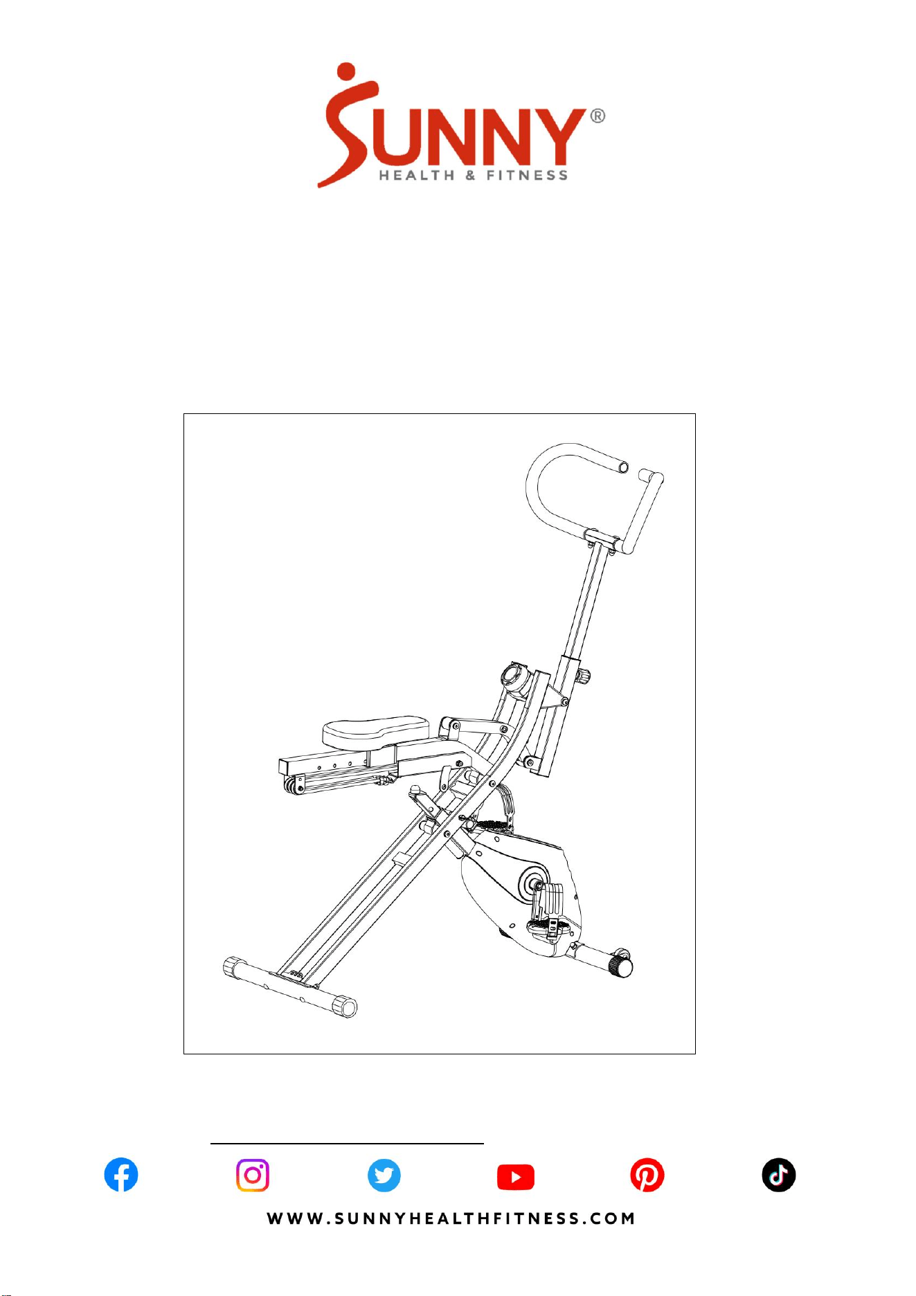
PRE-ASSEMBLY CHECK LIST
Before you start to assemble, please make sure all parts are included.
No.
Description
Spec.
Qty.
No.
Description
Spec.
Qty.
1
Front Support
1
63L/R
Pedal
YH-30X
1 pr.
6
Adjusting Tube
1
81
Seat
T45X180X300
1
7
Handlebar Adjusting
Tube
1
A
Manual
1
8
Handlebar
1
B
Thank You Card
1
11
Front Stabilizer
1
C
Hardware Package
1
12
Rear Stabilizer
1
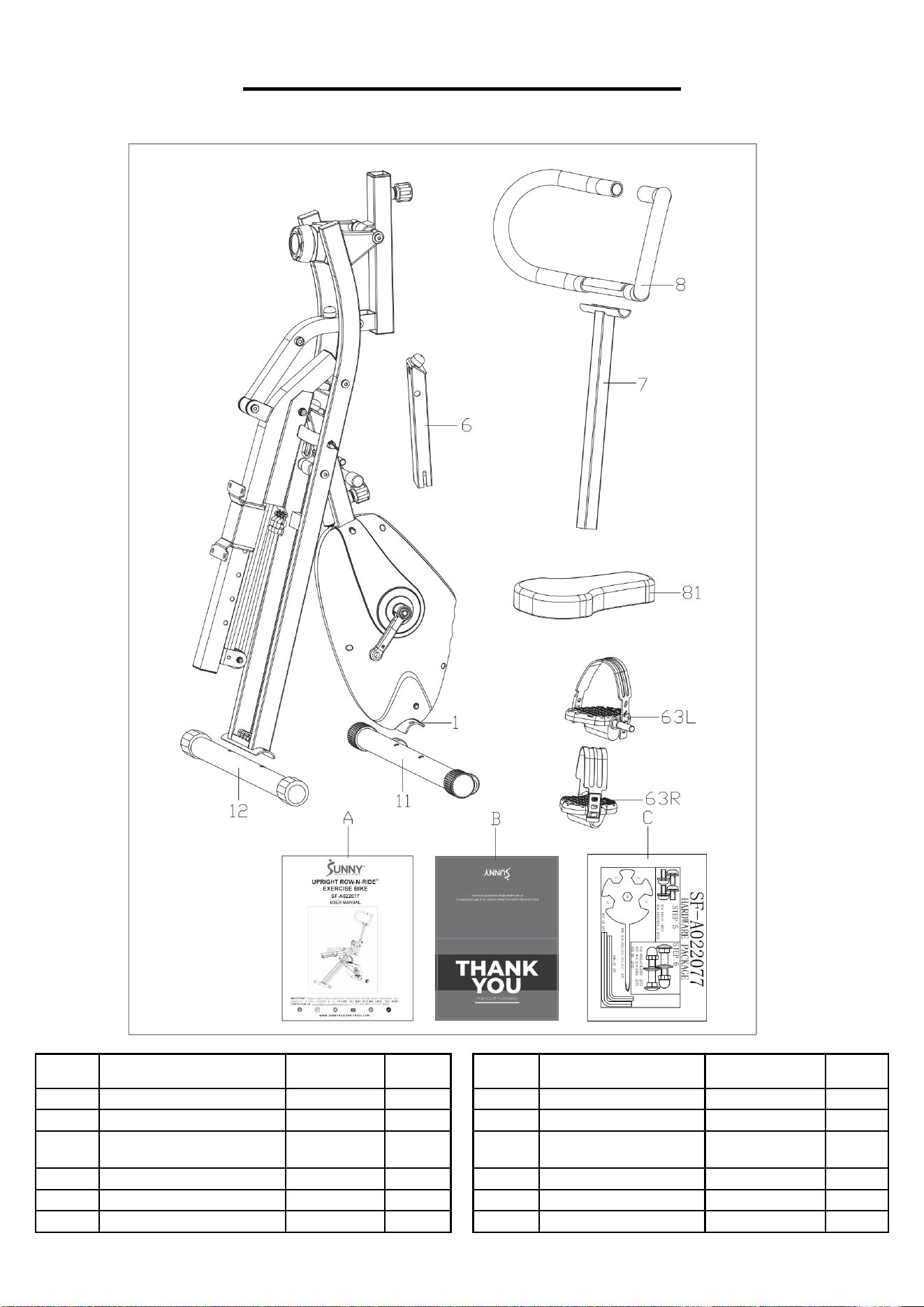
3
HARDWARE PACKAGE
Ordering Replacement Parts (U.S. and Canadian Customers only)
Please provide the following information in order for us to accurately identify the part(s) needed:
✓ The model number (found on cover of manual)
✓ The product name (found on cover of manual)
✓ The part number found on the “EXPLODED DIAGRAM” (page 13) and “PARTS LIST” (pages
14-15)
Please contact us at [email protected] or 1-877-90SUNNY (877-907-8669).
4
ASSEMBLY INSTRUCTIONS
We value your experience using Sunny Health and Fitness products. For assistance with parts or
troubleshooting, please contact us at support@sunnyhealthfitness.com or 1-877-90SUNNY
(877-907-8669).
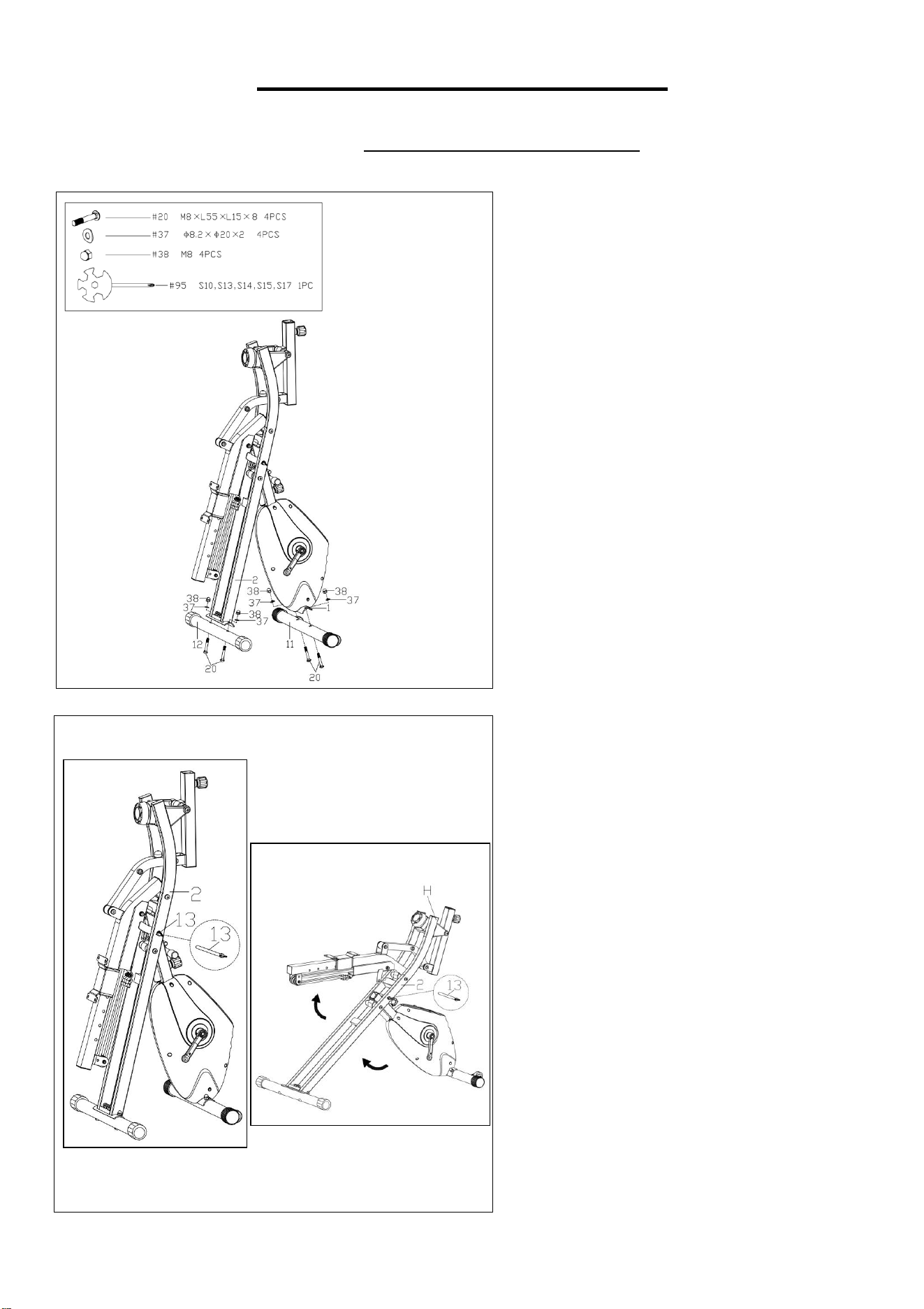
STEP 1
Remove the 2 Carriage Bolts (No. 20), 2
Arc Washers (No. 37) and 2 Cap Nuts
(No. 38) from the Front Stabilizer (No.
11) using Spanner (No. 95).
Attach the Front Stabilizer (No. 11) to
the Front Support (No. 1) with 2
Carriage Bolts (No. 20), 2 Arc Washers
(No. 37) and 2 Cap Nuts (No. 38) that
were just removed using Spanner (No.
95).
Remove the 2 Carriage Bolts (No. 20), 2
Arc Washers (No. 37) and 2 Cap Nuts
(No. 38) from the Rear Stabilizer (No.
12) using Spanner (No. 95).
Attach the Rear Stabilizer (No. 12) to the
Supporting Tube (No. 2) with 2 Carriage
Bolts (No. 20), 2 Arc Washers (No. 37)
and 2 Cap Nuts (No. 38) that were just
removed using Spanner (No. 95).
STEP 2
Pull out the Pull Pin (No. 13) from the
Supporting Tube (No. 2) as shown in
Fig. A.
Put you hand on the H position and unfold
as shown in Fig. B, insert the Pull Pin
(No. 13) back into the Supporting Tube
(No. 2).
Fig. B
Fig. A
5
We value your experience using Sunny Health and Fitness products. For assistance with parts or
troubleshooting, please contact us at [email protected] or 1-877-90SUNNY
(877-907-8669).
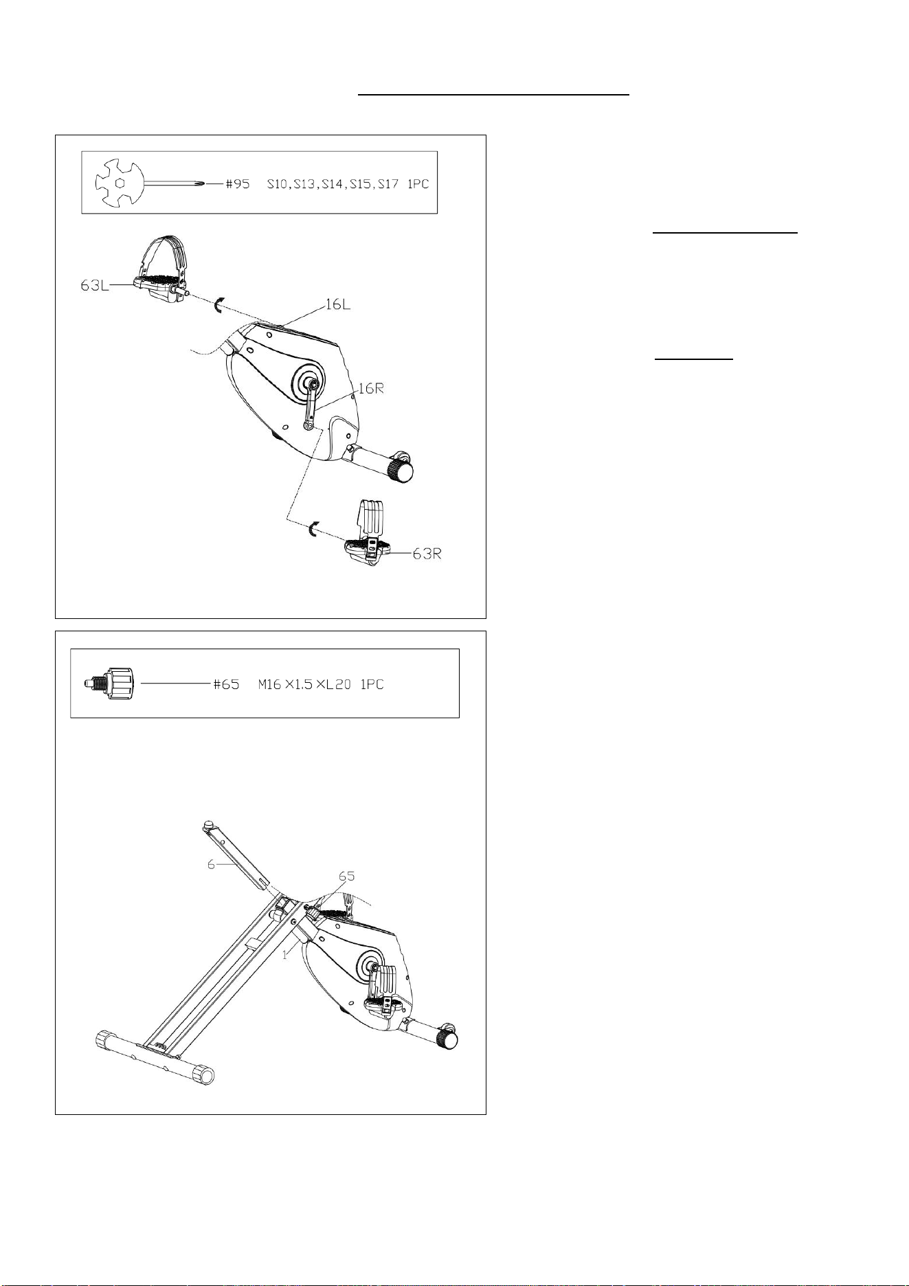
STEP 3
Attach the Left Pedal (No. 63L) to the
Left Crank (No. 16L). Turn the Left
Pedal (No. 63L) counter-clockwise as
tightly as you can with your hand. Then
secure using Spanner (No. 95).
Attach the Right Pedal (No. 63R) to the
Right Crank (No. 16R). Turn the Right
Pedal (No. 63R) clockwise as tightly as
you can with your hand. Then secure
using Spanner (No. 95).
STEP 4
Loosen and pull the Spring Knob (No.
65) outward, insert the Adjusting Tube
(No. 6) to the Front Support (No. 1),
adjust to the desire position, then re-insert
and tighten the Spring Knob (No. 65) to
secure the Adjusting Tube (No. 6) in
place.
6
We value your experience using Sunny Health and Fitness products. For assistance with parts or
troubleshooting, please contact us at [email protected] or 1-877-90SUNNY
(877-907-8669).
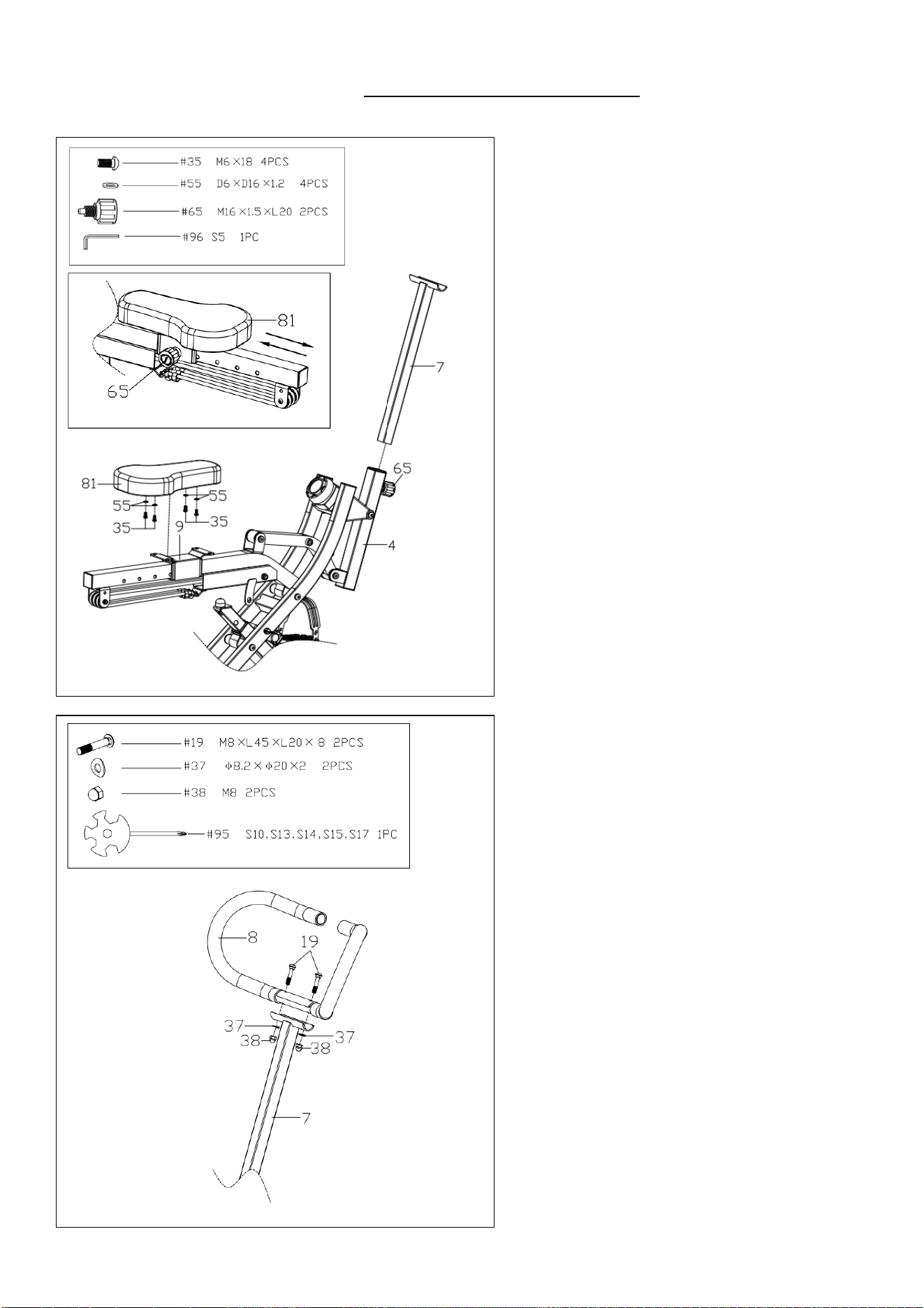
STEP 5
Loosen and pull the Spring Knob (No.
65) outward, insert the Handlebar
Adjusting Tube (No. 7) to the Handlebar
Adjusting Casing Tube (No. 4), adjust to
the desire position, then re-insert and
tighten the Spring Knob (No. 65) to
secure the Handlebar Adjusting Tube
(No. 7) in place.
Tighten the Seat (No. 81) to the Seat
Supporting Plate (No. 9) with 4 Screws
(No. 35) and 4 Flat Washers (No. 55)
using Allen Wrench (No. 96).
NOTE: Loosen and pull the Spring Knob
(No. 65) outward, you can adjust the Seat
(No. 81) in front and rear position. Once
adjusted, re-insert and tighten the Spring
Knob (No. 65) to secure the Seat (No.
81) in place, as Fig. C showed.
STEP 6
Fix the Handlebar (No. 8) to the
Handlebar Adjusting Tube (No. 7) with 2
Carriage Bolts (No. 19), 2 Arc Washers
(No. 37) and 2 Cap Nuts (No. 38) with
Spanner (No. 95).
THE ASSEMBLY IS COMPLETE!
Fig. C
7
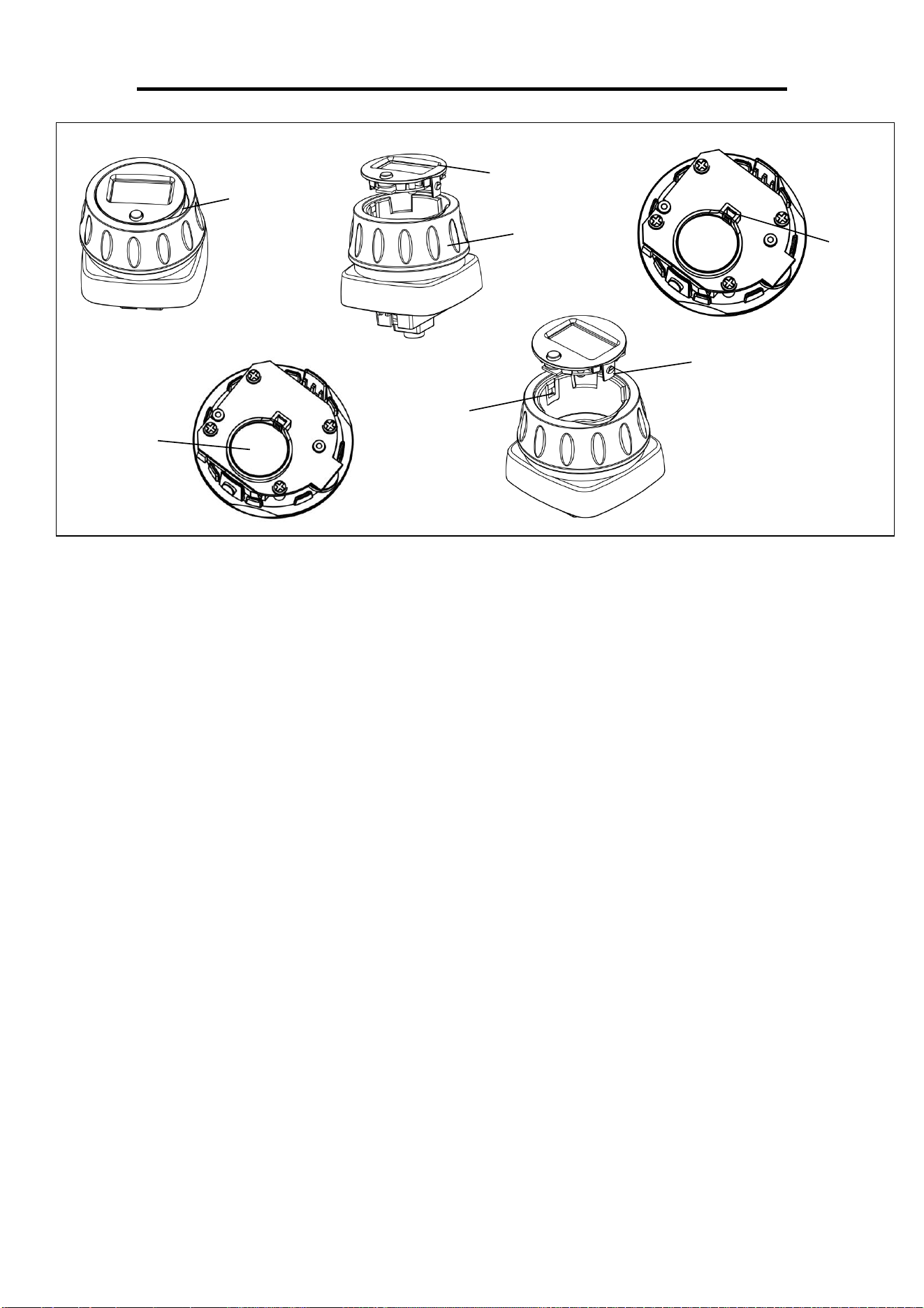
BATTERY INSTALLATION & REPLACEMENT
BATTERY INSTALLATION
1. Take out 1 CR2032 battery from the PE bag for manual.
2. Put one finger in the gap and pull up the meter upper cover (see Fig. 1).
3. Remove the meter upper cover from the meter bottom cover (see Fig. 2).
4. Put the battery into the battery seat, press down until you hear a click, then the battery is in
place (see Fig. 4). NOTE: The lettered side of the battery is facing up.
5. Point 2 button points on meter upper cover to 2 stuck points on meter bottom cover, then press
back the meter upper cover (see Fig. 5).
The installation is complete!
BATTERY REPLACEMENT
1. Put one finger in the gap and pull up the meter upper cover (see Fig. 1).
2. Remove the meter upper cover from the meter bottom cover (see Fig. 2).
3. Press the buckle of meter upper cover, then the battery will pop out (see Fig. 3).
4. Remove the old battery, and put a new battery into the battery seat, press down until you hear a
click, then the battery is in place (see Fig. 4). NOTE: The lettered side of the battery is facing
up.
5. Point 2 button points on meter upper cover to 2 stuck points on meter bottom cover, then press
back the meter upper cover (see Fig. 5).
The replacement is complete!
BATTERY DISPOSAL
Dispose the battery according to the laws and regulations of your local region.
Gap
Meter Upper
Cover
Stuck
Point
Fig. 1
Fig. 2
Fig. 3
Fig. 4
Fig. 5
Meter Bottom
Cover
Buckle
Battery
Seat
Button
Point
8
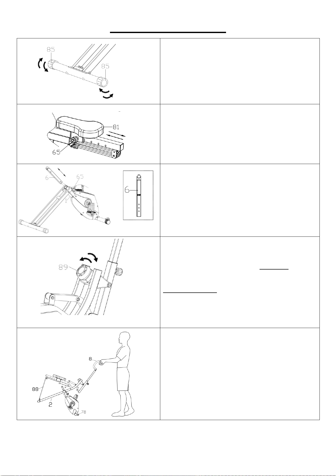
ADJUSTMENT GUIDE
ADJUSTING THE BALANCE
In order to achieve a smooth and comfortable ride,
you must ensure that the bike is stable and secure.
If you notice that the bike is unbalanced during
use, you should adjust the Rear End Caps (No.
85) located on the rear stabilizer until the bike
becomes levelled with the floor surface.
ADJUSTING THE SEAT
Loosen and pull the Spring Knob (No. 65)
outward, you can adjust the Seat (No. 81) in front
and rear position. Once adjusted, re-insert and
tighten the Spring Knob (No. 65) to secure the
Seat (No. 81) in place.
ADJUSTING THE SEAT HEIGHT
Loosen and pull the Spring Knob (No. 65)
outward, you can adjust the Adjusting Tube (No.
6). Once adjusted, re-insert and tighten the Spring
Knob (No. 65) to secure the Adjusting Tube (No.
6) in place.
ADJUSTING THE TENSION
Adjust the tension by rotating the Tension
Controller with Meter (No. 89) clockwise to
increase the level of resistance. Rotate the
Tension Controller with Meter (No. 89)
counter-clockwise to decrease the level of
resistance.
Tension levels are set at Level 1 being the lowest
and Level 8 being the highest.
MOVING THE BIKE
CAUTION: Before moving, please make sure the 3
Resistance Bands (No. 88) are connected to
Supporting Tube (No. 2).
Hold the Handlebar (No. 8) and press the bike
down until the Transportation Wheels (No. 78)
touch the ground. With the Transportation
Wheels (No. 78) on the ground, you can transport
the bike to the desired location with ease.
9
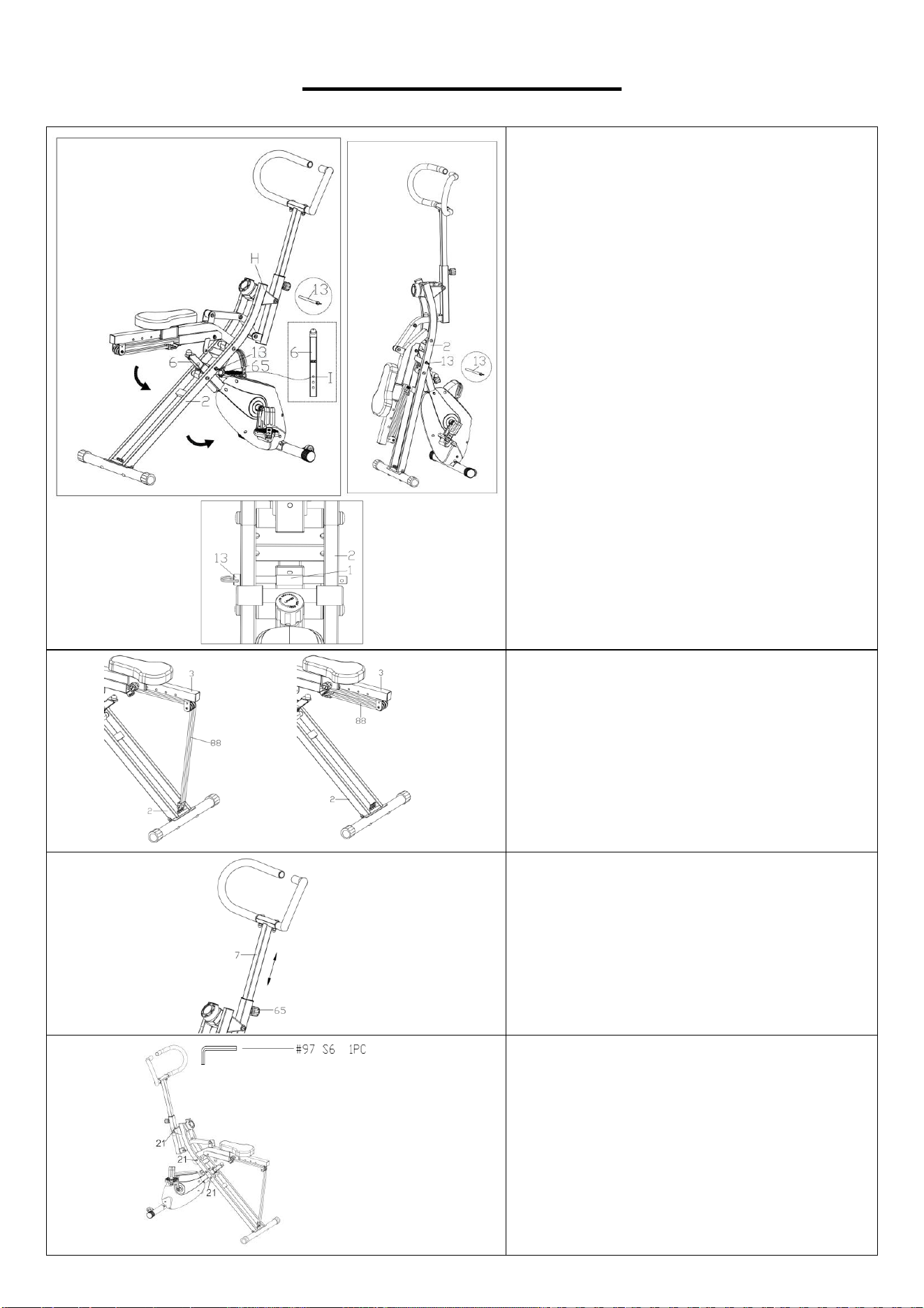
ADJUSTMENT GUIDE
FOLDING THE BIKE
Loosen and pull the Spring Knob (No. 65)
outward, adjust the Adjusting Tube (No.
6) to the hole marked I.
Pull out the Pull Pin (No. 13) from the
Supporting Tube (No. 2) as shown in Fig.
D. Put your hand in the H position and fold
the bike as the arrow showed on Fig. D.
Insert the Pull Pin (No. 13) back into the
Supporting Tube (No. 2) as shown in Fig.
E.
NOTE: Make sure Pull Pin (No. 13) is
through the holes on Front Support (No.
1) and Supporting Tube (No. 2) as shown
in Fig. F.
ADJUSTING THE RESISTANCE BAND
You can adjust the difficulty of your
exercise by adjusting the Resistance
Bands (No. 88). To reduce difficulty,
unhook Resistance Bands (No. 88) from
the Supporting Tube (No. 2) and connect
the Resistance Bands (No. 88) to the
hooks on the Seat Bracket (No. 3).
ADJUSTING THE HANDLEBAR
Loosen and pull the Spring Knob (No. 65)
outward, raise or lower the Handlebar
Adjusting Tube (No. 7) to desired height.
Re-insert and tighten the Spring Knob
(No. 65) to secure the Handlebar
Adjusting Tube (No. 7) in place.
TIGHTEN THE SCREWS
When the Screws (No. 21) are loosened,
you can tighten them with Allen Wrench
(No. 97).
Fig. D
Fig. E
Fig. F
10
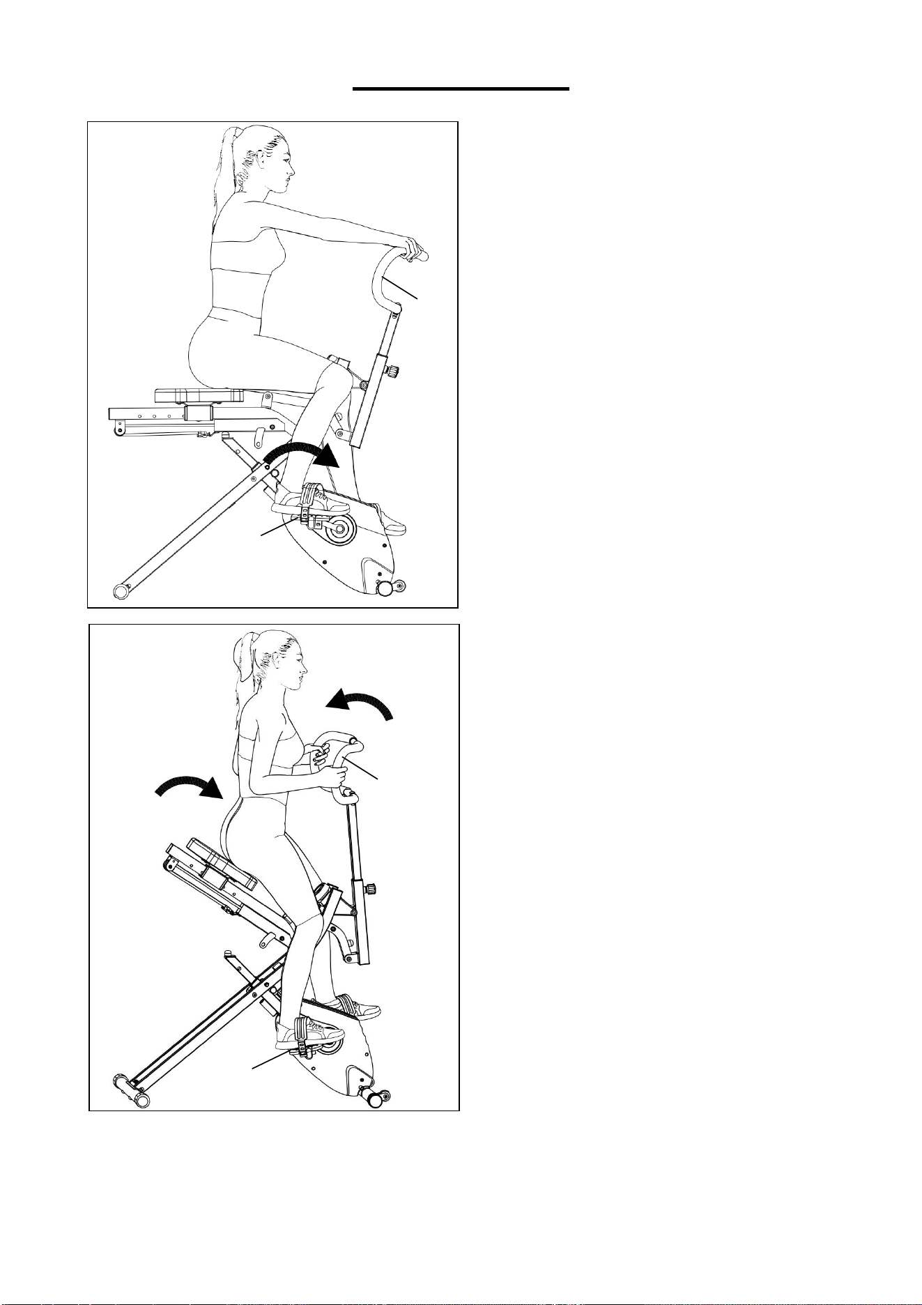
USAGE GUIDE
The Upright Row-N-Ride
®
Exercise Bike
allows you to work out in multiple ways.
You can use it as an exercise bike or use it
as a Row-N-Ride.
When using as an exercise bike, place
your hand on the Handlebar (No. 8), keep
your hand still, and step on the Pedals
(No. 63L/R) as shown in the left picture.
8
When using as a Row-N-Ride, place your
hand on the Handlebar (No. 8), keep step
on the Pedals (No. 63L/R) and pull the
Handlebar (No. 8) towards you as shown
in the left picture.
8
63L/R
63L/R

11
EXERCISE METER
SPECIFICATIONS:
TMR (TIME)--------------------------------00:00~99:59 MIN:SEC
SPM (REPS/MIN)-------------------------0~9999 STROKES/MIN
CNT (COUNT)-----------------------------0~9999 STROKES
TOT (TOTAL COUNT)-------------------0~9999 STROKES
SPD (SPEED)------------------------------0.00~999.9 MPH
RPM (CADANCE)-------------------------0~9999 ROTATION/MIN
DIST (DISTANCE)-------------------------0.00~999.9 MILES
ODO (TOTAL DISTANCE)---------------0.00~999.9 MILES
CAL (CALORIES)-------------------------0.0~9999 KCAL
KEY FUNCTION:
MODE: To select the function you want. Hold the key for 4 seconds to have all function values
reset (Except TOT and ODO).
OPERATION PROCEDURES:
AUTO ON/OFF: The meter will be automatically shut off if there is no signal coming in for 4
minutes. The meter will be auto-powered when start exercise or press the key.
FUNCTION:
TMR (TIME): Accumulates the workout time during exercise.
SPM (REPS/MIN): Displays the strokes per minute during exercise.
CNT (COUNT): Accumulates strokes while exercising.
TOT (TOTAL COUNT): Displays the total number of strokes since batteries were installed.
SPD (SPEED): Displays the speed during exercise.
RPM (CADANCE): Displays the rotations per minute during exercise.
DIST (DISTANCE): Accumulates the distance of each workout.
ODO (TOTAL DISTANCE): Accumulates the total distance since batteries were installed.
CAL (CALORIES): Count the total calories from exercise start to end.
NOTE: When only using the ROW-N-RIDE, meter will only accumulate SPM/CNT/TOT. When
only using the exercise bike, meter will only accumulate SPD/RPM/DIST/ODO.
BATTERY:
If the meter display is abnormal, please re-install the new battery and try again. This meter uses
one “CR2032” battery.

12
APP CONNECTION:
1. Scan the QR code below to download the SunnyFit app onto your mobile device.
2. If this is your first time using the SunnyFit app, follow the in-app instructions to register for your
free SunnyFit account and log in.
3. Ensure that the Bluetooth function is turned on from your mobile device.
4. To connect the equipment to the SunnyFit app:
a. From the “Workout” tab, press on the “Search” button to search for your equipment.
b. Once your equipment appears on the list, tap the “Select” button to confirm.
c. NOTE: If your equipment does not appear on the "Searching for Equipment" list, check the
EXERCISE METER on your equipment to ensure that it is not in sleep mode and your
phone's Bluetooth function is on, then tap "Retry" to search again.
d. Once your equipment shows up on the “Workout” tab as “Currently Selected”, your
equipment is now ready to display, track, and record your equipment’s workout stats on the
app!
5. If you are unable to replicate these steps, or have any other issues with the SunnyFit app,
to request support (“Me” tab -> “Contact Us”).
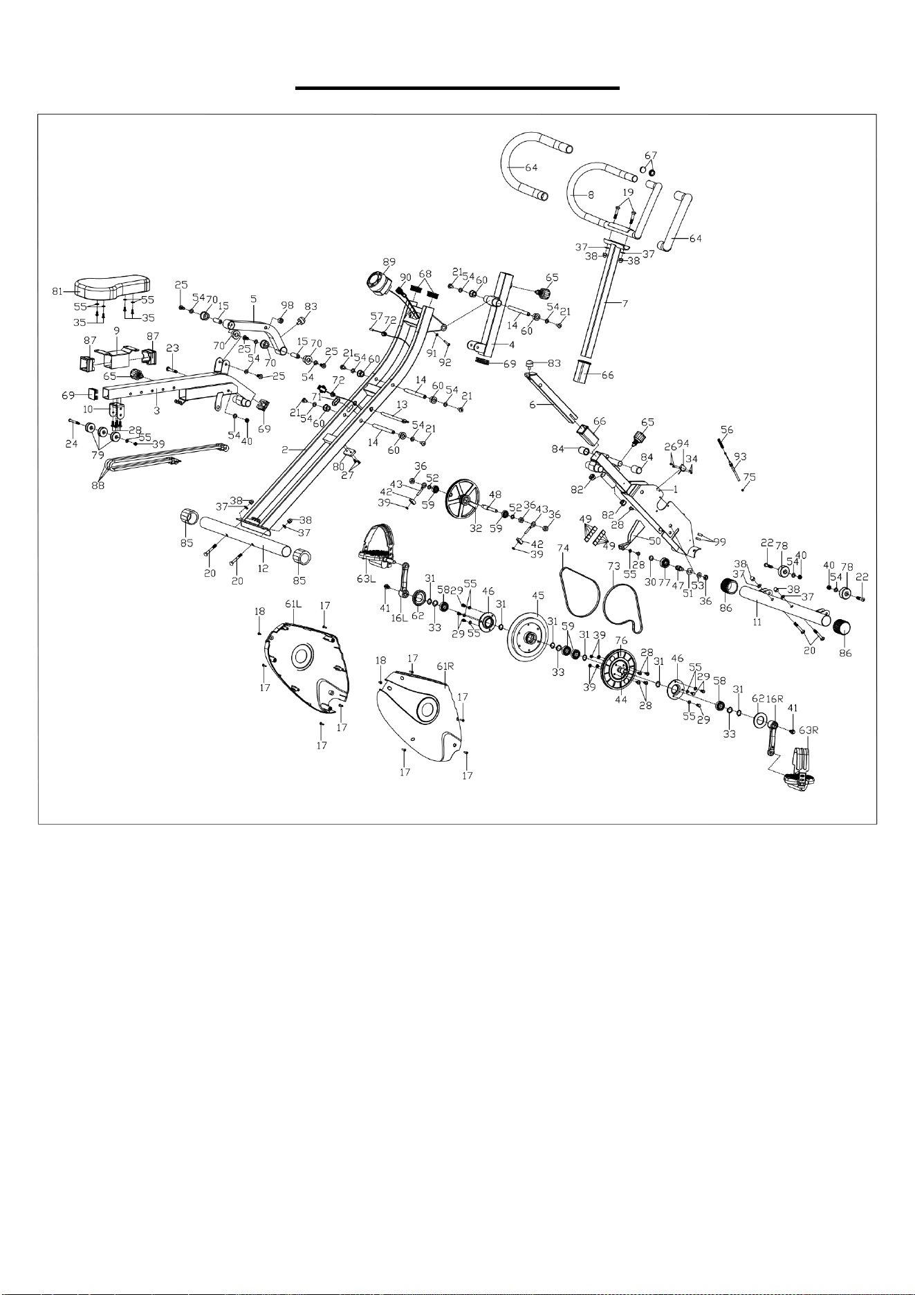
13
EXPLODED DIAGRAM
14
PARTS LIST
No.
Description
Spec.
Qty.
No.
Description
Spec.
Qty.
1
Front Support
1
43
Adjusting Belt Bolt
M6X50
2
2
Supporting Tube
1
44
Centre Axle
Φ17X154
1
3
Seat Bracket
1
45
Flywheel
Φ150X27 1KG
1
4
Handlebar
Adjusting Casing
Tube
1
46
Bearing Bracket
Φ76X14
2
5
Linking Tube
1
47
Idler Shaft
Φ17X36
1
6
Adjusting Tube
1
48
Driven Shaft
Φ14X92.5
1
7
Handlebar
Adjusting Tube
1
49
Square Magnet
15X13X3
10
8
Handlebar
1
50
Magnetic Board
δ2X28X37.2
1
9
Seat Supporting
Plate
1
51
Flat Washer
D12XD24X1
1
10
U Shape Bracket
1
52
Flat Washer
D10XD14X1
2
11
Front Stabilizer
1
53
Flat Washer
D10XD20X2.0
1
12
Rear Stabilizer
1
54
Flat Washer
D8XD16X1.5
13
13
Pull Pin
Φ10X150XA134
1
55
Flat Washer
D6XD16X1.2
12
14
Rotating Shaft
Φ12X129
3
56
Compressed Spring
Φ8.1X51
1
15
Rotating Shaft
Φ14X39.8
2
57
Needle Inductor
L200mm
1
16L/R
Crank
1/2”
1 pr.
58
Bearing
6003RS
2
17
Screw
ST4.2X18
8
59
Bearing
6000RS
4
18
Screw
ST4.2X13
2
60
Alloy Sleeve
Φ12.1X16XΦ2
1X13XΦ25X3
6
19
Carriage Bolt
M8XL45XL20X8
2
61L/R
Belt cover
1 pr.
20
Carriage Bolt
M8XL55XL15X8
4
62
Crank Cover
Φ60XΦ30X8.5
2
21
Screw
M8X15
6
63L/R
Pedal
YH-30X
1 pr.
22
Screw
M8X38XL15
2
64
Foam Grip
Φ24XΦ31X56
0
2
23
Screw
M8X55X15
1
65
Spring Knob
M16X1.5XL20
3
24
Screw
M6X60X15
1
66
Seat Tube Sleeve
38X2
2
25
Screw
M8X18
4
67
Round Cap
Φ25X2.0
2
26
Screw
M3X10
2
68
Square Cap
40X20X2.0
2
27
Screw
M5X10
2
69
Square Cap
38X38X2.0
3
28
Phillips Screw
M6X12
10
70
Axle Sleeve
Φ32XΦ14.1X1
9.5
4
29
Hex Screw
M6X12
6
71
Plug
31.5X12.5
1
30
Axle Spring
Washer
D15
1
72
Plug
Φ12.5
2
31
Axle Spring
Washer
D17
6
73
Flat Belt
240PJ4
1
32
Belt Pulley
Φ150X29.6
1
74
Flat Belt
230PJ3
1
33
Wave Washer
D17
3
75
Plug
Φ6.2
1
34
Hex Nut
M3
2
76
Belt Pulley
Φ154
1
35
Screw
M6X18
4
77
Idle Wheel
Φ35X13
1
36
Hex Nut
M10X1.0
4
78
Transportation
Wheel
Φ42X20.5
2
37
Arc Washer
Φ8.2XΦ20X2
6
79
Pulley
Φ36X15
3
38
Cap Nut
M8
6
80
Rubber Block
49X27X7
1
39
Nylon Nut
M6
7
81
Seat
T45X180X300
1
40
Nylon Nut
M8
3
82
Plug
Φ22X1.5
2
41
Flange Bolt
M8X20
2
83
Cushion
Φ25X20.5XM8
X12.5
2
42
U Shape Mat
δ3X30X20
2
84
Sleeve
Φ19
2

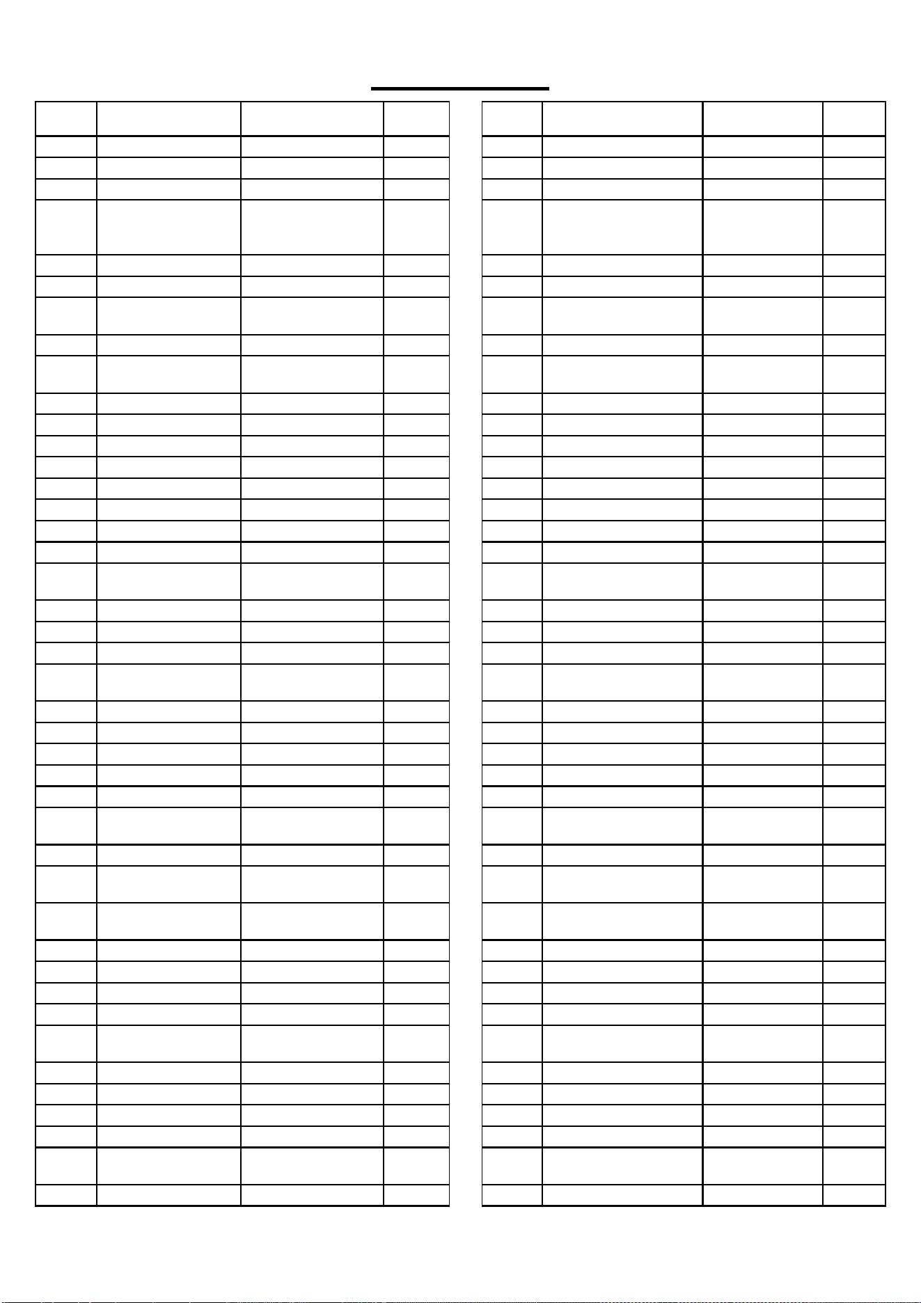
15
No.
Description
Spec.
Qty.
No.
Description
Spec.
Qty.
85
Rear End Cap
Φ42
2
93
Tension Wire
L1200mm
1
86
Front End Cap
Φ42
2
94
Inductor
L400mm
1
87
Sleeve
50X39XL32
2
95
Spanner
S10,S13,S14,
S15,S17
1
88
Resistance Band
Φ8X760
3
96
Allen Wrench
S5
1
89
Tension Controller
with Meter
1
97
Allen Wrench
S6
1
90
Connecting Wire
L600mm
1
98
Round Magnet
15X6
1
91
Flat Washer
D5
1
99
EVA Mat
8X15X65
2
92
Screw
M5X25
1
Version 1.0