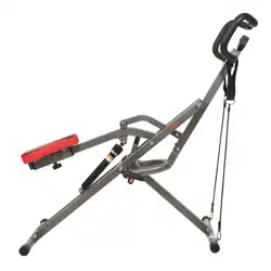
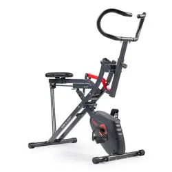
USER MANUAL for Squat Assist Trainer
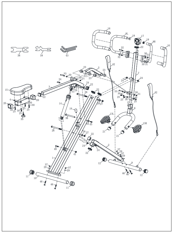
EXPLODED DIAGRAM
HARDWARE PACKAGE
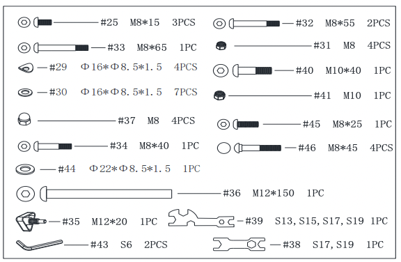
PARTS LIST
| No. |
Description |
Spec. |
Qty. |
| 1 |
Main Frame |
|
1 |
| 2 |
Front Support Tube |
|
1 |
| 3 |
Seat Tube |
|
1 |
| 4 |
Seat Support |
|
1 |
| 5 |
Connection Tube |
|
1 |
| 6 |
Pedal Connecting Tube |
|
1 |
| 7 |
Middle Post Tube |
|
1 |
| 8L |
Left Handlebar |
|
1 |
| 8R |
Right Handlebar |
|
1 |
| 9 |
Front Stabilizer |
|
1 |
|
10
|
Rear Stabilizer |
|
1 |
| 11 |
Rear End Cap |
Φ38 |
2 |
| 12 |
Front End Cap |
Φ38 |
2 |
| 13L |
Left Pedal |
|
1 |
| 13R |
Right Pedal |
|
1 |
| 14 |
Hydraulic Cylinder |
|
1 |
| 15 |
Seat |
298*158*45 |
1 |
| 16 |
Foam Grip |
Φ25 |
2 |
| 17 |
Meter |
|
1 |
| 18 |
Handlebar End Cap |
Φ25 |
2 |
| 19 |
Buffer Column |
Φ26*51 |
1 |
| 20 |
Inner Bushing |
|
2 |
| 21 |
Round Plug |
|
2 |
| 22 |
Square Tube Plug |
|
7 |
|
|
| No. |
Description |
Spec. |
Qty. |
| 23 |
Plastic Sleeve |
|
4 |
| 24 |
Alloy Sleeve |
Φ19*Φ12.2*11 |
6 |
| 25 |
Hex Socket Screw |
M8*15 |
7 |
| 26 |
Outer Hexagon Bolt |
M12*165 |
2 |
| 27 |
Nylon Nut |
M12 |
2 |
| 28 |
Flat Washer |
Φ24*Φ13.5*2.5 |
2 |
| 29 |
Arc Washer |
Φ16*Φ8.5*1.5 |
4 |
| 30 |
Washer |
Φ16*Φ8.5*1.5 |
13 |
| 31 |
Nylon Nut |
M8 |
5 |
| 32 |
Hex Socket Bolt |
M8*55 |
2 |
| 33 |
Hex Socket Bolt |
M8*65 |
2 |
| 34 |
Hex Socket Bolt |
M8*40 |
1 |
| 35 |
Triangle Knob |
M12*20 |
1 |
| 36 |
Bolt |
M12*150 |
1 |
| 37 |
Nut |
M8 |
4 |
| 38 |
Spanner |
S17,S19 |
1 |
| 39 |
Spanner |
S13,S15,S17,S19 |
1 |
| 40 |
Hex Socket Bolt |
M10*40 |
1 |
| 41 |
Nylon Nut |
M10 |
1 |
| 42 |
Exercise Band |
Φ5*580 |
2 |
| 43 |
Allen Wrench |
S6 |
2 |
| 44 |
Washer |
Φ22*Φ8.5*1.5 |
1 |
| 45 |
Hex Socket Screw |
M8*25 |
1 |
| 46 |
Carriage Bolt |
M8*45 |
4 |
|
Ordering Replacement Parts (U.S. and Canadian Customers only)
Please provide the following information in order for us to accurately identify the part(s) needed:
✓ The model number (found on cover of manual)
✓ The product name (found on cover of manual)
✓ The part number found on the “EXPLODED DIAGRAM” and “PARTS LIST” (found near the front of the manual)
ASSEMBLY INSTRUCTIONS
We value your experience using Sunny Health and Fitness products. For assistance with parts or troubleshooting, please contact us at support 1-877-90SUNNY (877-907-8669).
 |
|
STEP 1:
Attach Rear Stabilizer (No. 10) to Main Frame (No. 1) with 2 Carriage Bolts (No. 46), 2 Arc Washers (No. 29), and 2 Nuts (No. 37). Tighten and secure with Spanner (No. 39).
Attach Front Stabilizer (No. 9) to Front Support Tube (No. 2) with 2 Carriage Bolts (No. 46), 2 Arc Washers (No. 29), and 2 Nuts (No. 37). Tighten and secure with Spanner (No. 39).
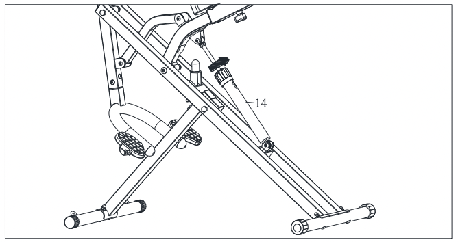
Attach Hydraulic Cylinder (No. 14) to the u-shaped seat on the top of Main Frame (No. 1) with 1 Hex Socket Bolt (No. 40) and 1 Nylon Nut (No. 41). Tighten and secure with Allen Wrench (No. 43) and Spanner (No. 39).
Note: The arrow mark of Hydraulic Cylinder (No.14) should be upward. Don’t secure the Hex Socket Bolt (No. 40) too tightly, otherwise the Hydraulic Cylinder (No. 14) won’t run smoothy.
|
 |
|
STEP 2:
Attach Seat Tube (No. 3) to Main Frame (No. 1) with 1 Bolt (No. 36), 1 Hex Socket Screw (No. 45) and 1 Washer (No. 44). Tighten and secure with 2 Allen Wrenches (No. 43).
Attach Hydraulic Cylinder (No. 14) to the u-shaped seat on the bottom of Seat Tube (No. 3) with 1 Hex Socket Bolt (No. 34) and 1 Nylon Nut (No. 31). Tighten and secure with Allen Wrench (No. 43) and Spanner (No. 39).
Note: Don’t secure the Hex Socket Bolt (No. 34) too tightly, otherwise the Hydraulic Cylinder (No. 14) won’t run smoothy
|
 |
|
STEP 3:
Remove the 4 Hex Socket Screws (No. 25) and 4 Washers (No. 30) form the Seat (No. 15) by Allen Wrench (No. 43). Put the Seat Support (No. 4) onto the Seat (No. 15) with 4 Hex Socket Screws (No. 25) and 4 Washers (No. 30) that were removed. Tighten and secure with Allen Wrench (No. 43).
Insert the Seat (No. 15) into the Seat Tube (No. 3), adjust the Seat (No. 15) to your desired position, then tighten and secure with Triangle Knob (No. 35).
|
 |
|
STEP 4:
Attach Pedal Connecting Tube (No. 6) into Middle Post Tube (No. 7) with 3 Hex Socket Screws (No. 25) and 3 Washers (No. 30). Tighten and secure with Allen Wrench (No. 43).
|
 |
|
STEP 5:
Remove 1 Outer Hexagon Bolt (No. 26), 1 Flat Washer (No. 28) and 1 Nylon Nut (No. 27) from Main Frame (No. 1) using Spanner (No. 38) and Spanner (No. 39).
Attach Middle Post Tube (No. 7) to Main Frame (No. 1) with 1 Outer Hexagon Bolt (No. 26), 1 Flat Washer (No. 28) and 1 Nylon Nut (No. 27). Tighten and secure with Spanner (No. 38) and Spanner (No. 39).
Attach the Connection Tube (No. 5) to the u-shaped seat on the bottom of Middle Post Tube (No. 7) with 1 Hex Socket Bolt (No. 33), 2 Washers (No. 30) and 1 Nylon Nut (No. 31). Tighten and secure with Allen Wrench (No. 43) and Spanner (No. 39).
Align the Left Pedal (No. 13L) with the left side of the Pedal Connecting Tube (No. 6) at 90°and gently insert the Left Pedal (No. 13L) into the Pedal Connecting Tube (No. 6). Turn the Left Pedal (No. 13L) counter-clockwise as tightly as you can with your hand. Then tighten and secure with Spanner (No. 39).
Align the Right Pedal (No. 13R) with the right side of the Pedal Connecting Tube (No. 6) at 90°and gently insert the Right Pedal (No. 13R) into the Pedal Connecting Tube (No. 6). Turn the Right Pedal (No. 13R) clockwise as tightly as you can with your hand. Then tighten and secure with Spanner (No. 39).
|
 |
|
STEP 6:
Attach Left Handlebar (No. 8L) and Right Handlebar (No. 8R) to Middle Post Tube (No. 7) with 2 Hex Socket Bolts (No. 32), 2 Washers (No. 30) and 2 Nylon Nuts (No. 31). Tighten and secure with Allen Wrench (No. 43) and Spanner (No. 39).
Insert the Meter (No. 17) into the Middle Post Tube (No. 7).
|
 |
|
STEP 7:
Connect 2 Exercise Bands (No. 42) to the hooks on the Front Stabilizer (No. 9), then hang the 2 Exercise bands (No. 42) to Left & Right Handlebars (No. 8L & No. 8R).
The assembly is complete!
|
BATTERY INSTALLATION & REPLACEMENT
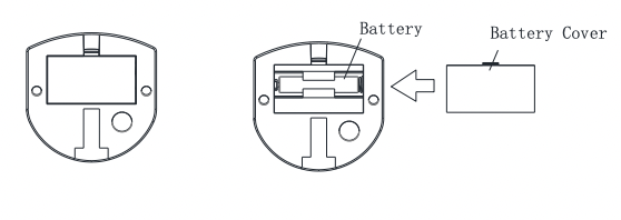
BATTERY INSTALLATION:
- 1. Take out 1 AA battery from meter box.
- 2. Press the buckle of battery cover on the Meter (No. 17), then remove battery cover.
- 3. Install 1 AA battery into the battery case on the back of the Meter (No. 17). Pay attention to the battery + and – poles before installing.
- 4. Press the buckle of battery cover, then put the battery cover back to the back of the Meter (No. 17).
The installation is complete!
BATTERY REPLACEMENT:
- 1. Press the buckle of battery cover on the back of the Meter (No. 17), then remove battery cover.
- 2. Remove the 1 old AA battery in the battery case and install 1 new AA battery into the battery case on the back of the Meter (No. 17). Pay attention to the battery + and – poles before installing.
- 3. Press the buckle of battery cover, then put the battery cover back to the back of the Meter (No. 17).
The replacement is complete!
NOTE: Dispose battery according to your state and regional guidelines.
ADJUSTING THE RESISTANCE
This rowing machine is designed with 12 levels of resistance. Turn the upper ring on the Hydraulic Cylinder (No. 14) so the arrow points to the desired resistance level, as shown on the drawing.
NOTE: Please do not adjust the resistance of the Hydraulic Cylinder (No. 14) during operation to avoid injury and damage to the rowing machine.
WARNING!
The Hydraulic Cylinder (No. 14) on this rowing machine is designed to be used up to 20 minutes per exercise session. Allow at least 20 minutes in between sessions for the Hydraulic Cylinder (No. 14) to properly cool down.
Caution: The Hydraulic Cylinder (No. 14) can generate excessive heat after long periods of use, making it unsafe to touch. Allow the Hydraulic Cylinder (No. 14) to cool before moving the rowing machine.
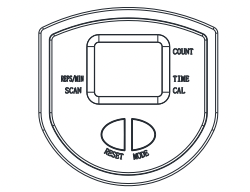
EXERCISE METER
SPECIFICATIONS:
TIME----------------------00:00~99:59MIN
REPS/MIN------------------0~9999
COUNT---------------------0~9999
CALORIES (CAL)-------------0~9999KCAL
KEY FUNCTIONS:
MODE: This key lets you to select and lock on to a particular function you want.
RESET: Press and hold the RESET key for 3~4 seconds to reset all the data. Change the battery will also reset all the data.
FUNCTIONS:
- TIME: Display the workout time while exercising.
- REPS/MIN: Displays current speed during workout time.
- COUNT: Accumulate workout count while exercising.
- CALORIES (CAL): Displays calories amount burned while exercising.
AUTO SCAN: The meter will rotate through the four functions in the following order:TIME-CALORIES-REPS/MIN-COUNT. Each function will be held for 4 seconds.
NOTE:
- Without any signal coming in 4-5 minutes, the LCD display will be shut off automatically.
- When there is signal input, the meter automatically turns on.
- If there is a possibility to see an improper display on the meter, please replace the batteries to have a good result.
- The meter use one 1.5V “AA” battery.