FULL BODY ADJUSTABLE
MULTIFUNCTION SMART ROW-N-RIDE
®
TRAINER
SF-A022070
USER MANUAL
IMPORTANT! Please retain owner’s manual for maintenance and adjustment instructions. Your
satisfaction is very important to us, PLEASE DO NOT RETURN UNTIL YOU HAVE CONTACTED
US: support@sunnyhealthfitness.com or 1- 877 - 90SUNNY (877-907-8669).

1
IMPORTANT SAFETY INFORMATION
We thank you for choosing our product. To ensure your safety and health, please use this equipment
correctly. It is important to read this entire manual before assembling and using the equipment. Safe
and effective use can only be achieved if the equipment is assembled, maintained, and used
properly. It is your responsibility to ensure that all users of the equipment are informed of all warnings
and precautions.
1. Before starting any exercise program, you should consult your physician to determine if you have
any medical or physical condition that could put your health and safety at risk or prevent you from
using the equipment properly. Your physician’s advice is essential if you are taking medication
that affects your heart rate, blood pressure or cholesterol level.
2. Be aware of your body’s signals. Incorrect or excessive exercise can damage your health. Stop
exercising if you experience any of the following symptoms: pain, tightness in your chest,
irregular heartbeat, shortness of breath, lightheadedness, dizziness, or feelings of nausea. If you
do experience any of these conditions, you should consult your physician before continuing with
your exercise program.
3. Keep children and pets away from the equipment. The equipment is designed for adult use only.
4. Use the equipment on a solid, flat level surface with a protective cover for your floor or carpet. To
ensure safety, the equipment should have at least 2 feet (60 cm) of free space all around it.
5. Ensure that all nuts and bolts are securely tightened before using the equipment. The safety of
the equipment can only be maintained if it is regularly examined for damage and/or wear and
tear.
6. Always use the equipment as indicated. If you find any defective components while assembling
or checking the equipment, or if you hear any unusual noises coming from the equipment during
exercise, discontinue use of the equipment immediately and do not use until the problem has
been rectified.
7. Wear suitable clothing while using the equipment. Avoid wearing loose clothing that may
become entangled in the equipment.
8. Do not place fingers or objects into the moving parts of the equipment.
9. The maximum weight capacity of this unit is 220 lbs (100kgs).
10. The equipment is not suitable for therapeutic use.
11. To avoid bodily injury and/or damage to the product or property, proper lifting and moving are
required.
12. Your product is intended for use in cool and dry conditions. You should avoid storage in extremely
cold, hot or damp areas as this may lead to corrosion and other related problems.
13. This equipment is designed for indoor and home use only; it is not intended for commercial use.
2
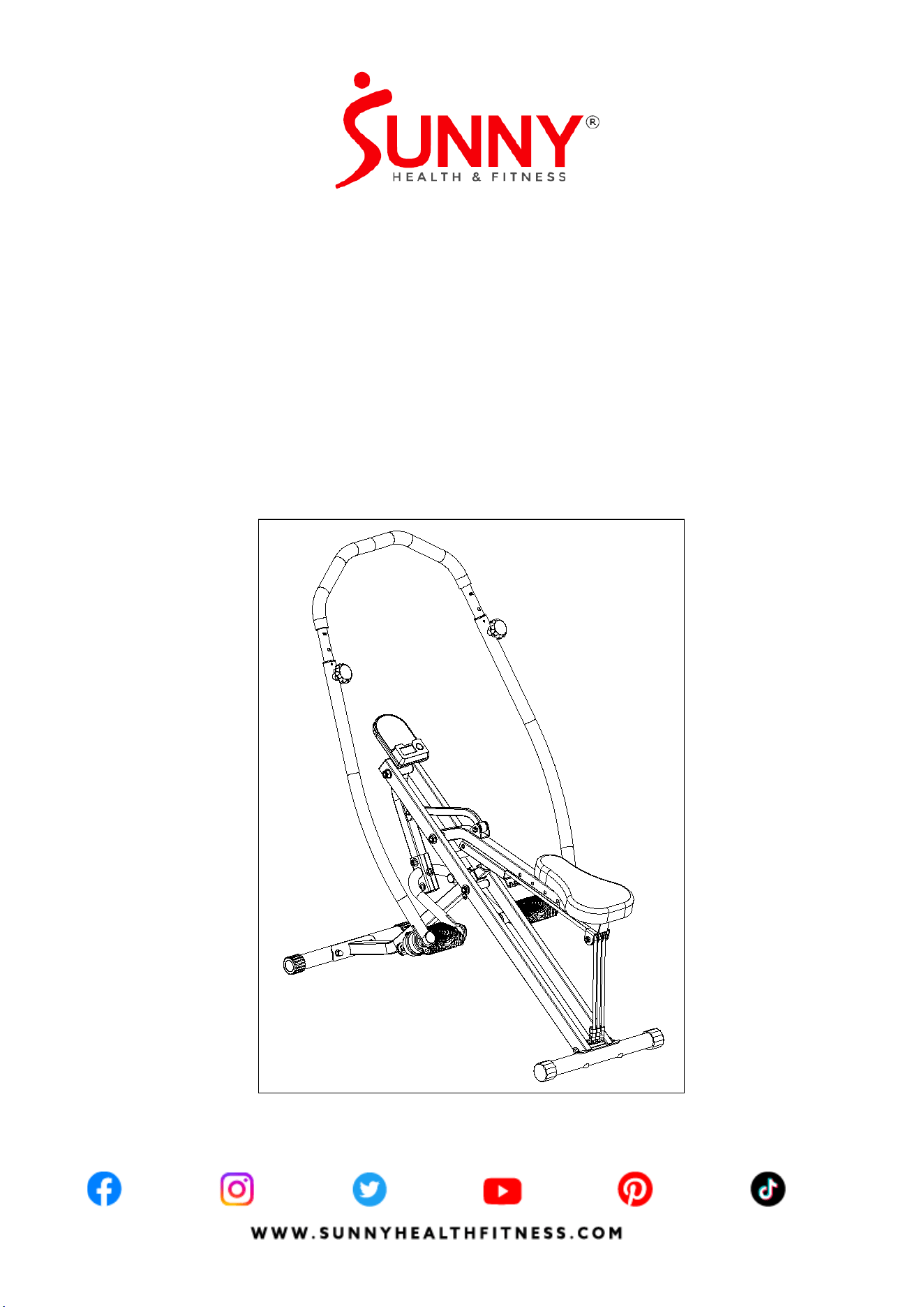
PRE-ASSEMBLY CHECK LIST
SF-A022070 HARDWARE PACKAGE
Step 1
Step 3
#29 Φ8*42.5 1PC
#6 M8*13 1PC
#12 M8*40.5 1PC
A S6 1PC
B S13-15-17 1PC
Step 5
#10 Φ52*L56*M12 2PCS
Step 7
#21 Φ47*40*M8 1PC
Step 4
#61 M8*15 6PCS
#62 Φ8*1.5 6PCS
#63 Φ8*Φ20*T1.5 6PCS
1
46
45
48
49
36
38
25
FULL BODY ADJUSTABLE
MULTIFUNCTION S MART ROW-N-RIDE
TRAINER
SF-A022070
USER MANUAL
MPORTANT! Please retain owner ’s manual for mai ntenance and
adjustment i nstructions. Yo ur satisfactio n is very import ant to us,
PLEASE DO NOT RETUR N UNTIL YOU HAVE C ONTACTED US :
support@sunnyhealthfitness.com or 1- 877 - 90SUNNY (877-907-8669).
UNNY
H E A L T H & F L T N E S S
f
W W W.S U N N Y H E A L T H F I T N E S S.C O M
A
B
18
41
C
D
THANK
YOU
FOR YOUR PURCHASE
If you have any questions, please contact us at (877) 90SUNNY or
email: sup [email protected]
UNNY
H E A L T H & F L T N E S S
No.
Description
Spec.
Qty.
No.
Description
Spec.
Qty.
1
Main Frame
1
46
Right Upper Handrail
1
18 Seat 1 48
Left Handrail
Assembly
1
25 Seat Tube 1 49
Right Handrail
Assembly
1
36
Front Stabilizer
Ø38*1.5*410
1
A
Hardware Package
1
38
Rear Stabilizer
Ø38*1.5*410
1
B
Thank You Card
1
41
Computer
BJHT-098
1
C
Manual
297*210
1
45
Left Upper Handrail
1
D
Battery
AAA
2
3
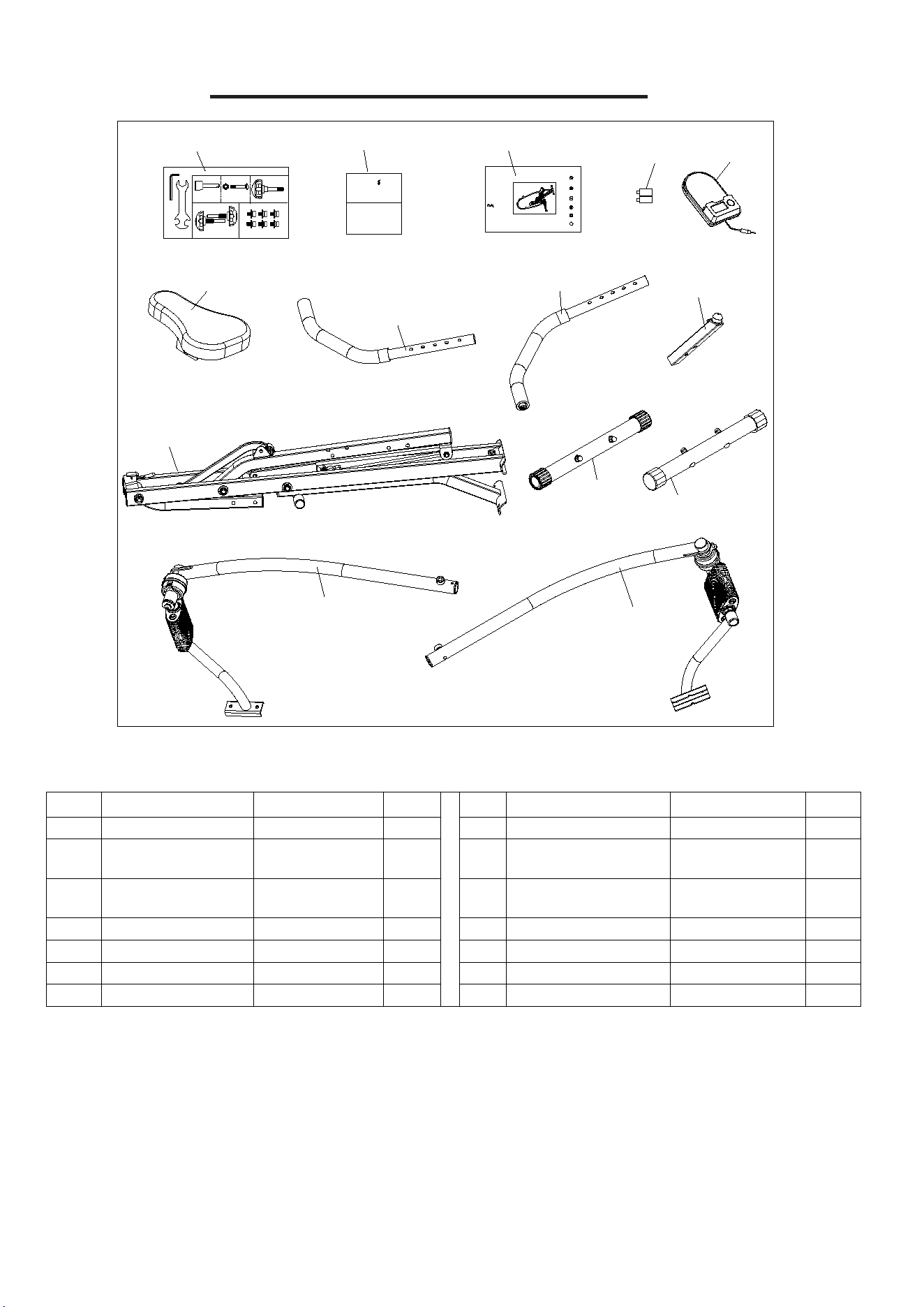
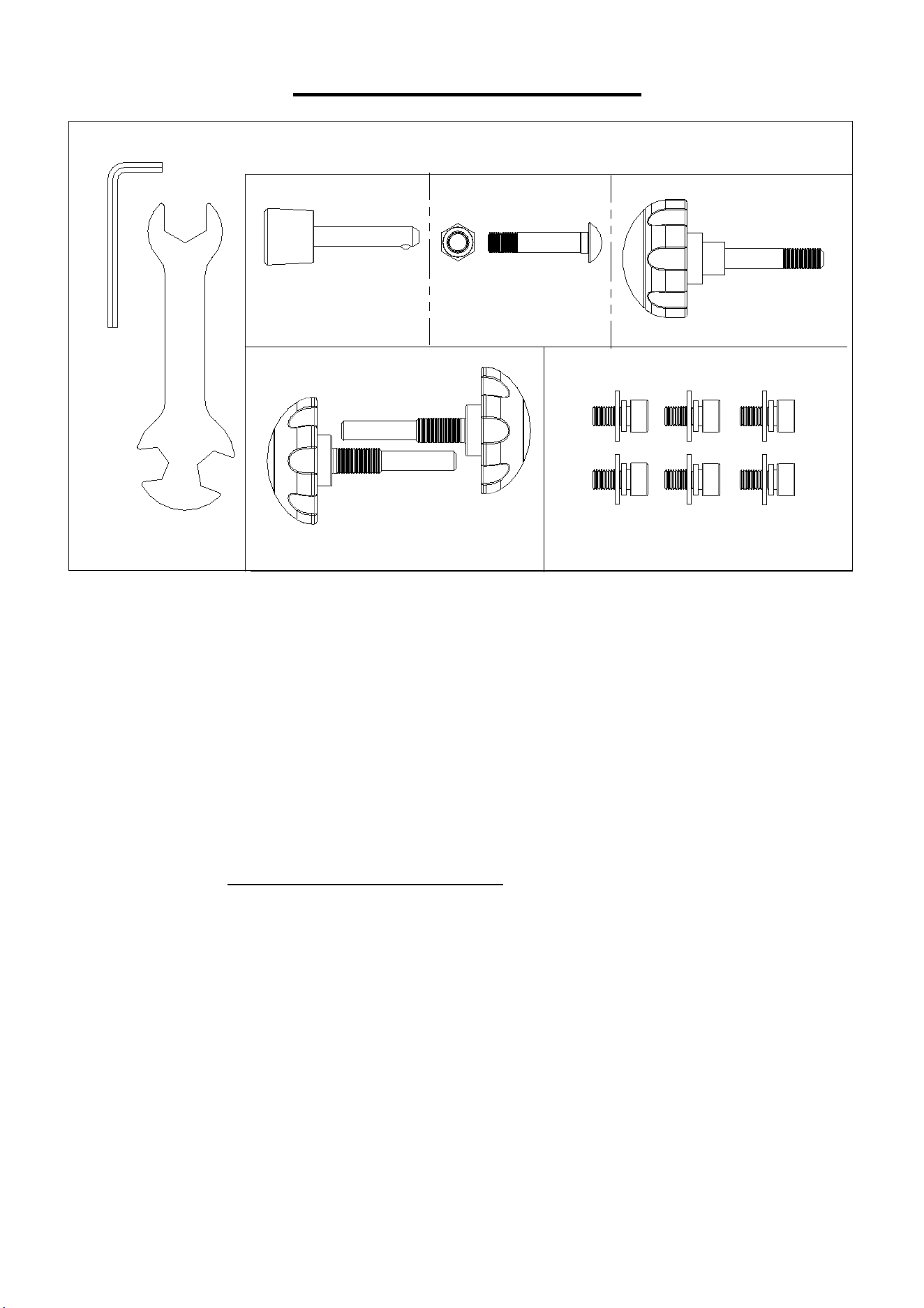
HARDWARE PACKAGE
SF-A022070 HARDWARE PACKAGE
Step 1
Step 3
#29 Φ8*42.5 1PC
#6
M8*1
3 1PC
#12 M8*40.5 1PC
A S6 1PC
B S13-15-17 1PC
Step 5
#10
Φ
52*L56*M12 2PCS
Step 7
#21
Φ
47*40*M8 1PC
Step 4
#61 M8*15 6PCS
#62
Φ
8*1.5 6PCS
#63
Φ
8*
Φ
20*T1.5 6PCS
Ordering Replacement Parts (U.S. and Canadian Customers only)
Please provide the following information in order for us to accurately identify the part(s) needed:
The model number (found on cover of manual)
The product name (found on cover of manual)
The part number found on the “EXPLODED DIAGRAM” (page 16) and “PARTS LIST” (page 17)
Please contact us at support@sunnyhealthfitness.com or 1- 877 - 90SUNNY (877-907-8669).
4
ASSEMBLY INSTRUCTIONS
We value your experience using Sunny Health and Fitness products. For assistance with parts or
troubleshooting, please contact us at support@sunnyhealthfitness.com or 1-877-90SUNNY
(877-907-8669).
1
1
#29
φ
8*42.5 1PC
1
29
25
32
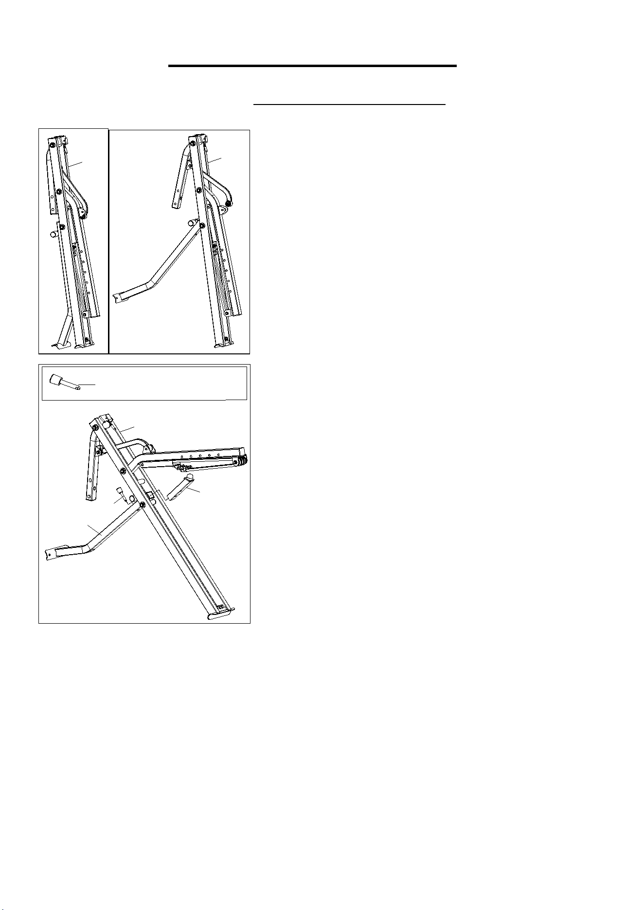
STEP 1:
Open the Main Frame (No. 1) as shown in the picture
on the left.
Take out the
Pin (No. 29)
from hardware package, Insert
the
Seat Tube (No. 25)
into the
Front Connecting Tube
(No. 32)
. Then insert and secure
with
Pin (No. 29)
.
5
We value your experience using Sunny Health and Fitness products. For assistance with parts or
troubleshooting, please contact us at support@sunnyhealthfitness.com or 1-877-90SUNNY
(877-907-8669).
#35 M8*48 2PCS
#33 M8*12 2PCS
B S13-15-17 1PC
#5
φ
16*
φ
8*T1.5 2PCS
35
36
5
33
5
33
32
#35 M8*48 2PCS
#33 M8*12 2PCS
B S13-15-17 1PC
#5
φ16*φ8*T1.5 2PCS
1
35
38
33
5
5
33
#12 M8*40.5 1PC
#6 M8*13 1PC
B S13-15-17 1PC
6
12
1
31
15
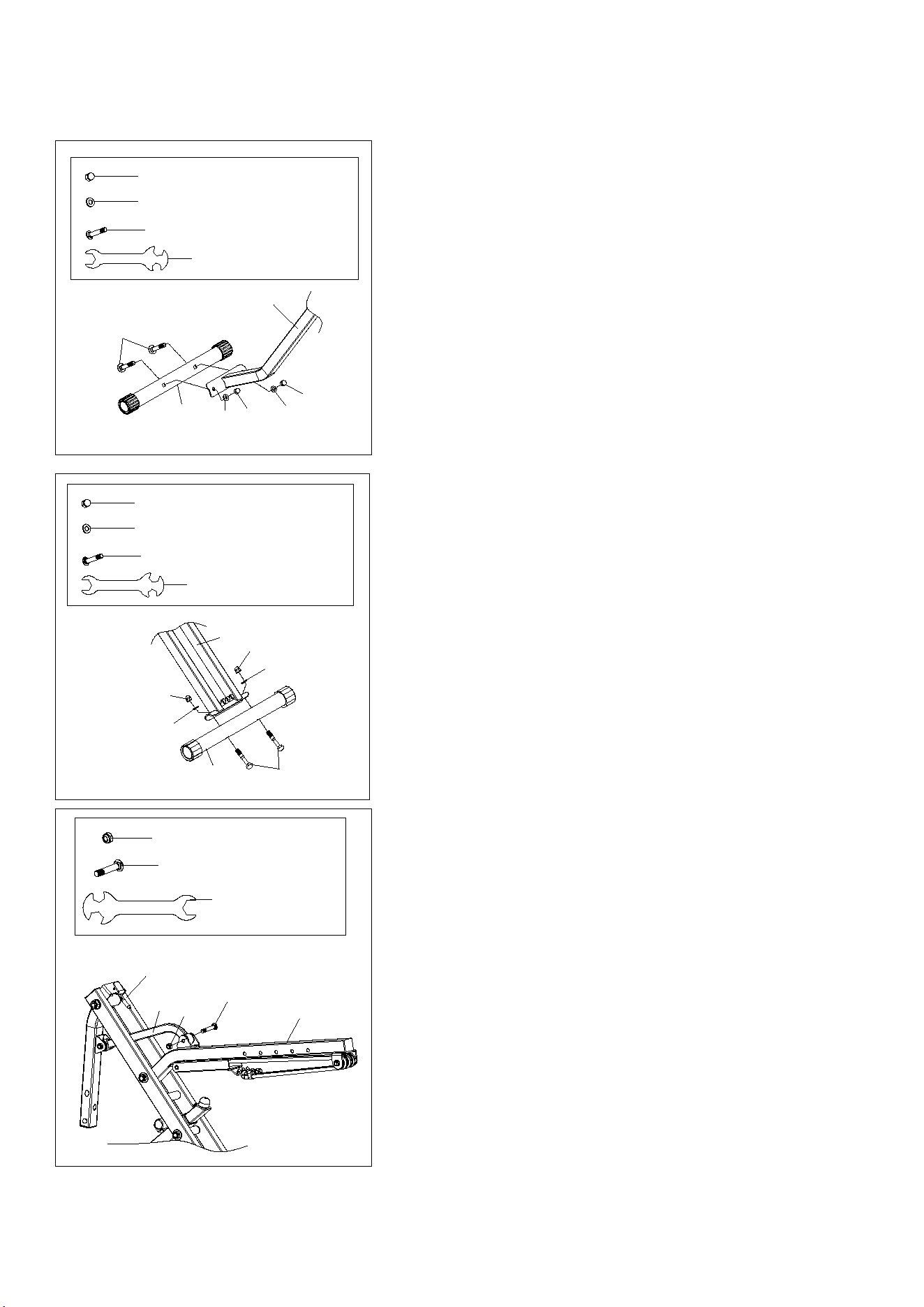
STEP 2:
Remove 2 Bolts (No. 35), 2 Nuts (No. 33) and 2
Washers (No. 5) from the Front Stabilizer (No. 36) with
Spanner (No. B). Attach Front Stabilizer (No. 36) to
Front Connecting Tube (No. 32) using 2 Bolts (No.
35), 2 Nuts (No
33)
and 2
Washers (No.
5
)
that
were removed. Tighten and
secure with Spanner
(No. B).
Remove 2 Bolts (No. 35), 2 Nuts (No. 33) and 2
Washers (No. 5) from the Rear Stabilizer (No. 38) with
Spanner (No. B). Attach Rear Stabilizer (No. 38) to
Main Frame (No. 1) using 2 Bolts (No. 35), 2 Nuts (No.
33) and 2 Washers (No. 5) that were removed. Tighten
and secure with Spanner (No. B).
STEP 3:
Take out the Hexagon Screw (No. 12) and Nut (No. 6)
from hardware package. Insert the Connecting Tube
(No. 15) into the metal bracket slot of Seat Connecting
Tube (No. 31). Then insert Hexagon Screw (No. 12)
into Seat Connecting Tube (No. 31) and secure Nut
(No. 6) using Spanner (No. B).
6
We value your experience using Sunny Health and Fitness products. For assistance with parts or
troubleshooting, please contact us at support@sunnyhealthfitness.com or 1-877-90SUNNY
(877-907-8669).
#62
φ
8*1.5 6PCS
#61 M8*15 6PCS
A S6 1PC
#63
φ
8*
φ
20*T1.5 6PCS
49
48
1
9
70
67
32
61
62
63
63
62
61
61
62
63
63
62
61
9
70
67
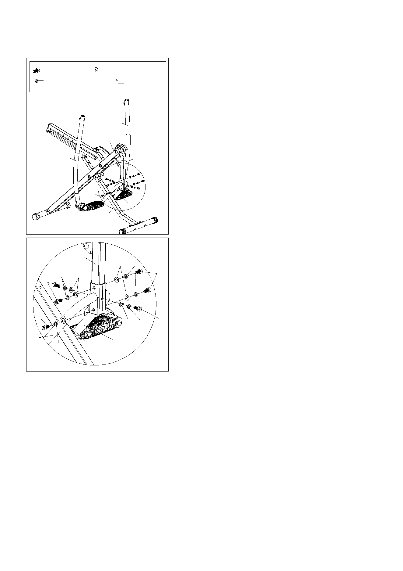
STEP 4:
Take out the 6 Hexagon Screws (No. 61), 6 Spring
Washers (No. 62) and 6 Washers (No. 63) from
hardware package.
Attach the Left Handrail (No. 48) and the Right
Handrail (No. 49) to the Pedal Connecting Tube
(No. 9) using 6 Hexagon Screws (No. 6), 6 Spring
Washers (No. 62) and 6 Washers (No. 63). Tighten
and secure with Allen Wrench (No. A).
7
We value your experience using Sunny Health and Fitness products. For assistance with parts or
troubleshooting, please contact us at support@sunnyhealthfitness.com or 1-877-90SUNNY
(877-907-8669).
#10 φ52*L56*M12 2PCS
1
48
49
10
46
45
10
41A
1
41
60
41A
60
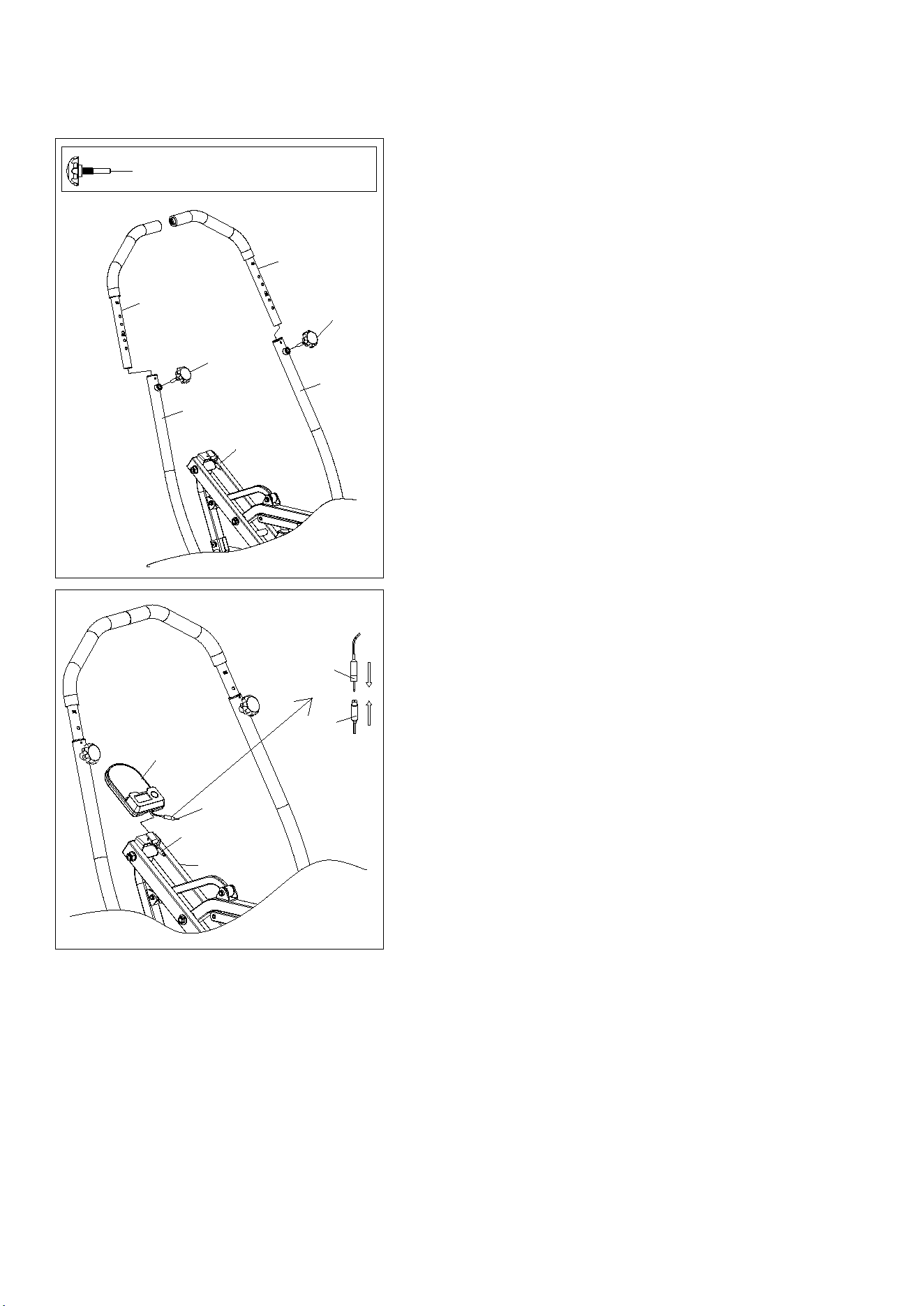
STEP 5:
Take out the 2 Knobs (No. 10) from hardware
package.
Note: Before assembly, make sure the Left & Right
Upper Handrail (No. 45 & No. 46) need to be
adjusted to the same height.
Insert Left Upper Handrail (No. 45) into Left
Handrail (No. 48). Then insert and secure with Knob
(No. 10) after adjusting to proper height.
Insert Right Upper Handrail (No. 46) into Right
Handrail (No. 49). Then insert and secure with Knob
(No. 10) after adjusting to proper height.
STEP 6:
Connect the Computer Wire (No. 41A) to the
Sensor (No. 60).
Insert the Computer (No. 41) onto the tab on the
Main Frame (No. 1).
8
We value your experience using Sunny Health and Fitness products. For assistance with parts or
troubleshooting, please contact us at support@sunnyhealthfitness.com or 1-877-90SUNNY
(877-907-8669).
#21
φ47*40*M8 1PC
19
1
18
21
31
42
31
42
31
1
1
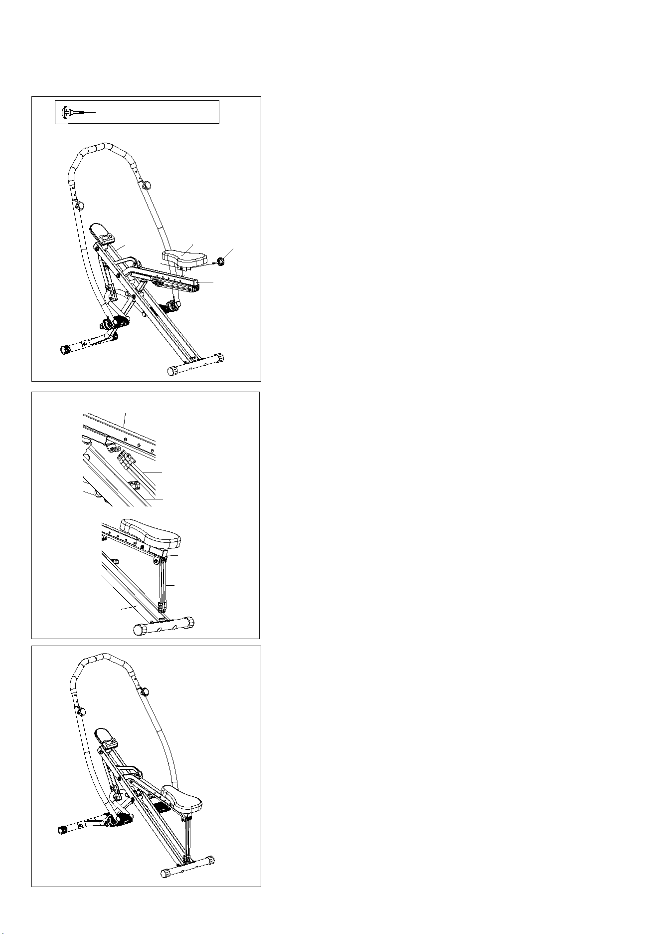
STEP 8:
Unhook Exercise Bands (No. 42) from the Seat
Connecting Tube (No. 31), and connect the Exercise
Bands (No. 42) to the hooks on the Main Frame (No.
1).
The assembly is complete!
STEP 7:
Take out the Knob (No. 21) from the hardware
package.
Attach the Fixed Iron Sheet (No. 19) to the Seat
Connecting Tube (No. 31), adjust the Seat (No. 18)
to your desired position, then tighten and secure with
the Knob (No. 21).
9
MAINTENANCE & ADJUSTMENT GUIDE
10
10
45
46
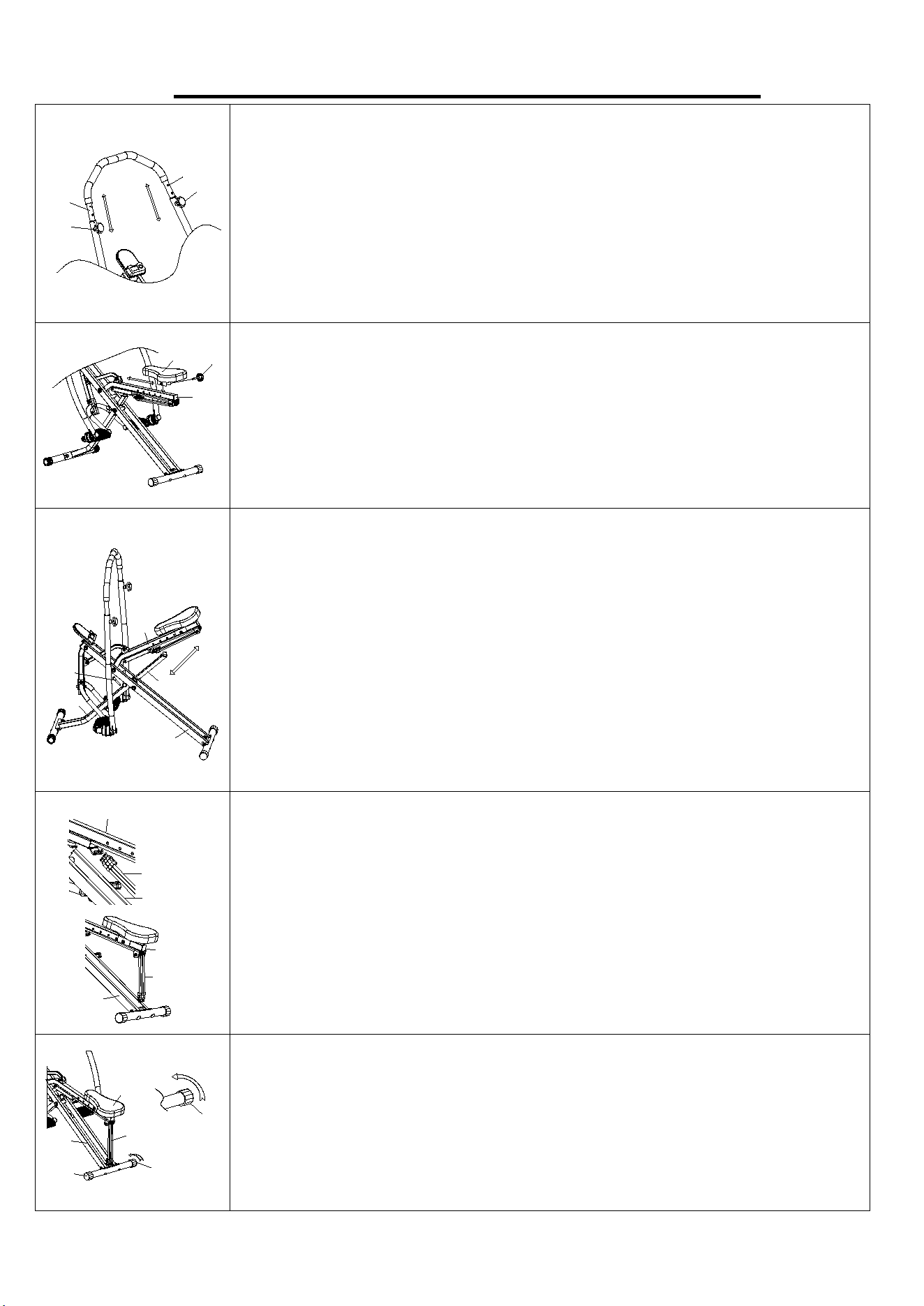
ADJUSTING THE HANDLEBAR
Loosen and remove the Knob (No. 10). Raise or lower the Left & Right
Upper Handrail (No. 45 & No. 46) to desired height. Reinsert and tighten
the Knob (No. 10).
Note: The Left & Right Upper Handrail (No. 45 & No. 46) need to be
adjusted to the same height.
ADJUSTING THE SEAT
Loosen and remove the Knob (No. 21) located under the Seat Connecting
Tube (No. 31). Move the Seat (No. 18) to desired position, then re-tighten
the Knob (No. 21).
25
29
31
1
32
ADJUSTING THE SEAT TUBE
To adjust the Seat Tube (No. 25), lift the Seat Connecting Tube (No. 31).
Remove the Pin (No. 29) from Front Connecting Tube (No. 32) and raise
or lower the Seat Tube (No. 25) to desired position. Re-insert the Pin (No.
29) to secure. Then lower the Seat Connecting Tube (No. 31). Raising or
lowering Seat Tube (No. 25)
will change the difficulty
of your exercise.
NOTE: Make sure Exercise Bands (No. 42) are not hooked to Main Frame
(No. 1) when adjusting the Seat Tube (No. 25). Do not extend the Seat
Tube (No. 25) to pass “MAX” line.
42
31
42
31
1
1
ADJUSTING THE EXERCISE BAND
You can adjust the difficulty of your exercise by adjusting the Exercise
Bands (No. 42). To reduce difficulty, unhook Exercise Bands (No. 42) from
the Main Frame (No. 1) and connect the Exercise Bands (No. 42) to the
hooks on the Seat Connecting Tube (No. 31).
37
37
1
37
31
42
ADJUSTING THE BALANCE
In order to achieve a smooth and comfortable ride, you must ensure that the
bike is stable and secured. If you notice that the bike is unbalanced during
use, you should adjust the End Caps (No. 37) located on the rear stabilizer
until the bike becomes levelled with the floor surface.
18
21
31
10
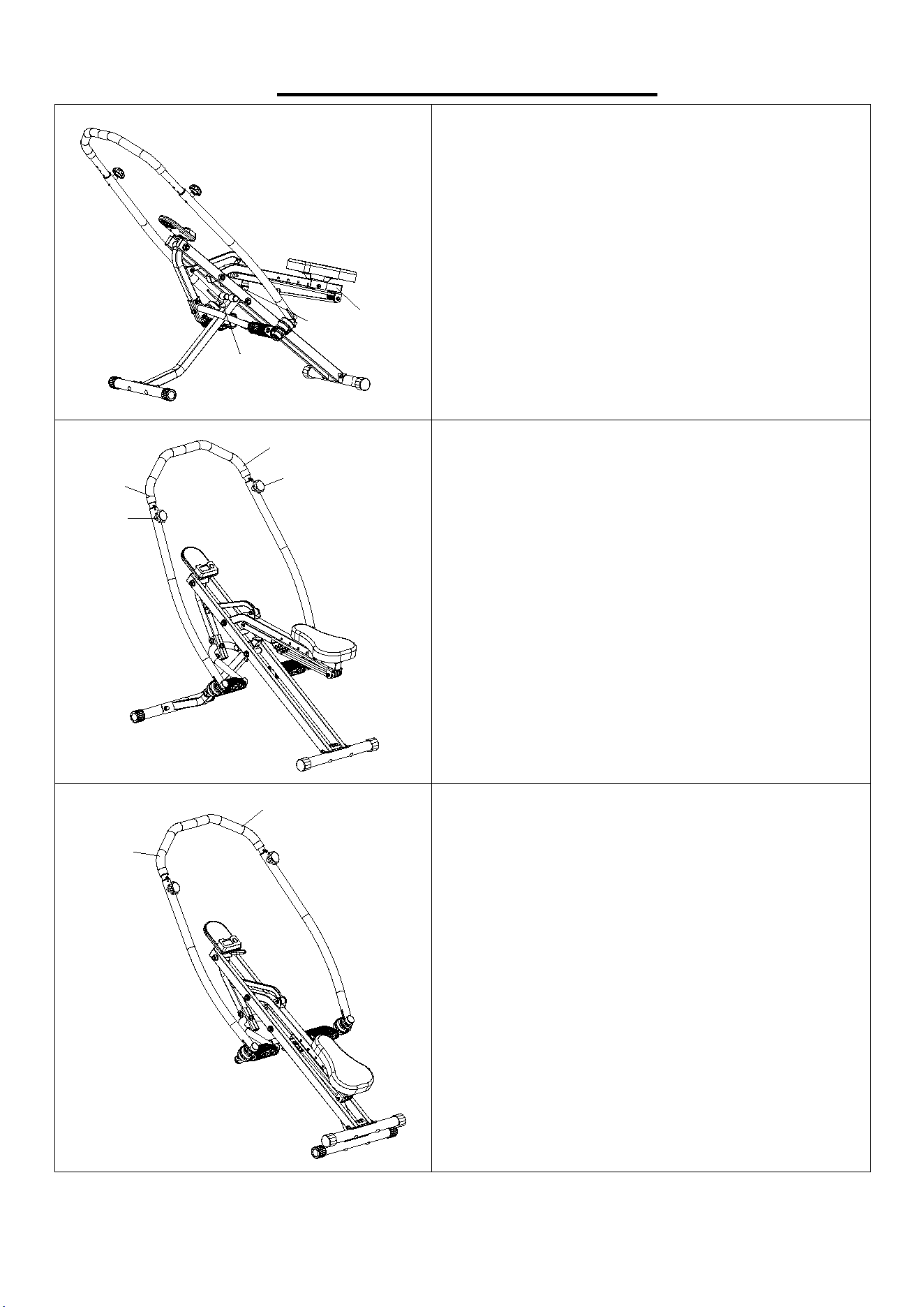
FOLDING INSTRUCTIONS
30,4
31
25
29
A. Adjust the Seat Tube (No. 25) to the lowest level
by the Pin (No. 29).
NOTE: Make sure Exercise Bands (No. 42) are
not connected to Main Frame (No. 1) when folding.
10
46
10
45
B. Adjust the Left & Right Upper Handrail (No. 45
& No. 46) to the lowest level by Knob (No. 10).
46
45
C. Hold the Left & Right Upper Handrail (No. 45 &
No. 46) and fold the product.
11
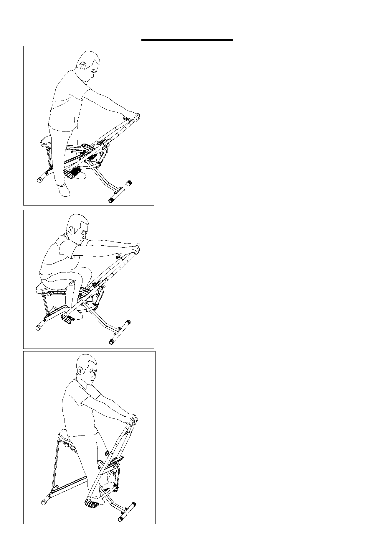
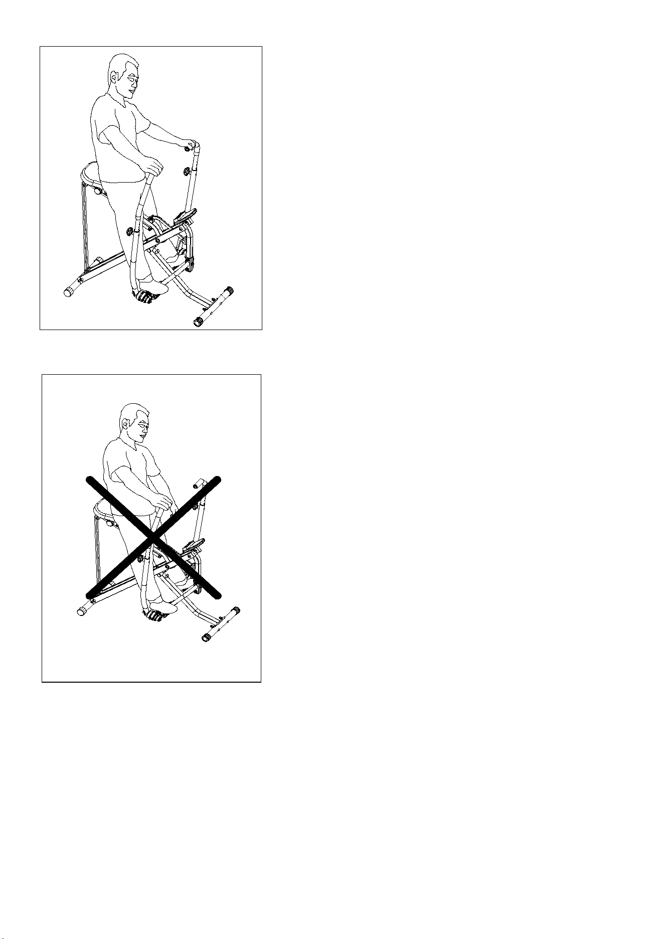
USAGE GUIDE
38
38,1
38
When using the smart Row-N-Ride
®
trainer, you should
stand on the ground with your legs crossed on both
sides of the machine and place your hands on the upper
handrail first.
After sitting down, hold the upper handrail with both
hands and then step on the pedals with both feet.
While pushing forward with both feet, grab the upper
handrail with both hands and pull back.
12
38
You can also separate your hands and row forward or
backward at the same time.
WARNING: It is strictly prohibited to use only one hand
for rowing, as it may pose danger to the user and
damage the service life of the equipment.
13
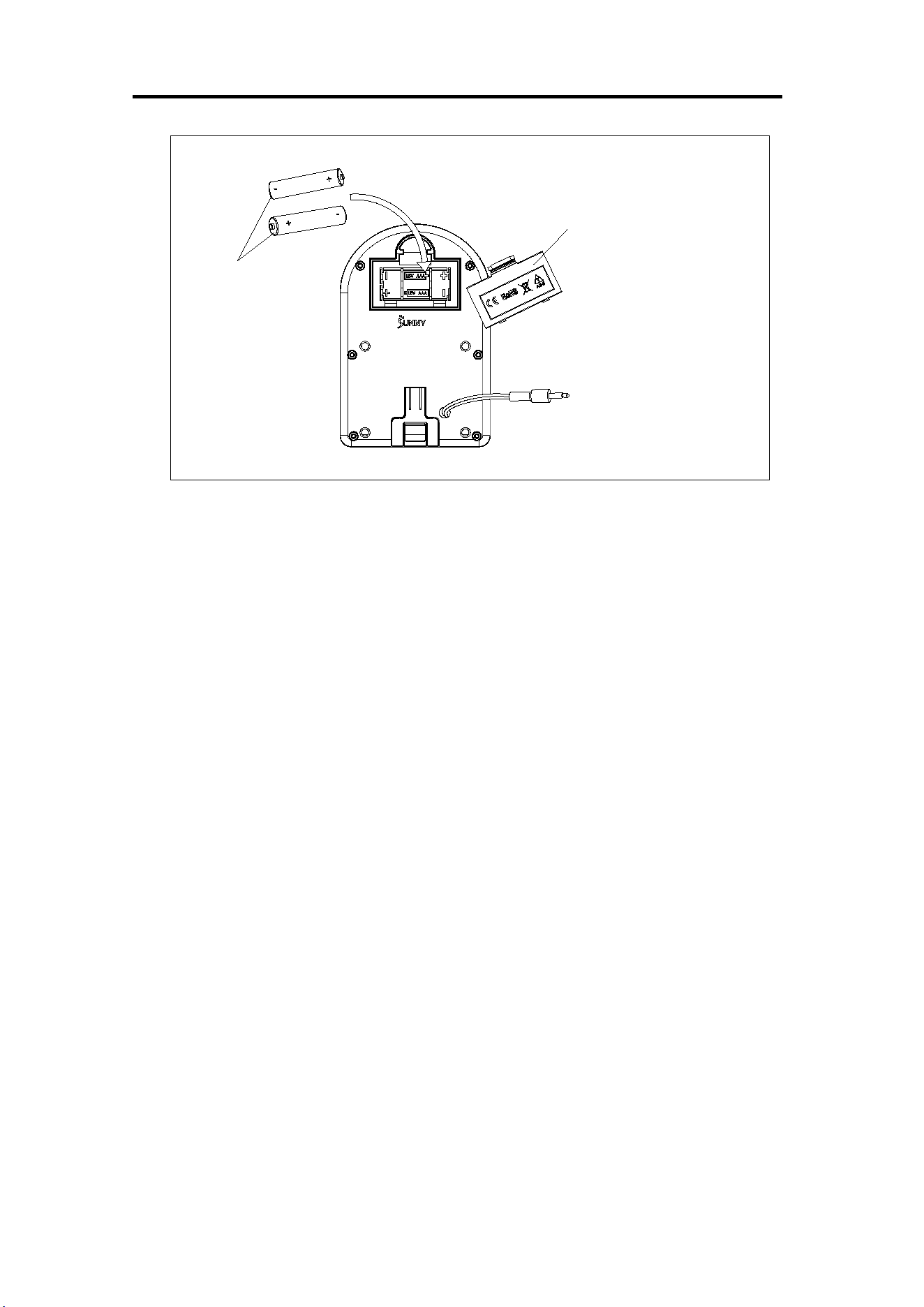
BATTERY INSTALLATION & REPLACEMENT
Battery Cover
Battery
BATTERY INSTALLATION:
1. Take out 2 AAA batteries from the computer box.
2. Press the buckle of battery cover on the Computer (No. 41), then remove battery cover.
3. Install 2 AAA batteries into the battery case on the back of the Computer (No. 41). Pay attention
to the battery + and – poles before installing.
4. Press the buckle of battery cover, then put the battery cover back to the back of the Computer (No.
41).
The installation is complete!
BATTERY REPLACEMENT:
1. Press the buckle of battery cover on the back of the Computer (No. 41), then remove battery
cover.
2. Remove the 2 old AAA batteries in the battery case and install 2 new AAA batteries into the battery
case on the back of the Computer (No. 41). Pay attention to the battery + and – poles before
installing.
3. Press the buckle of battery cover, then put the battery cover back to the back of the Computer (No.
41).
The replacement is complete!
NOTE: Dispose battery according to your state and regional guidelines.
14
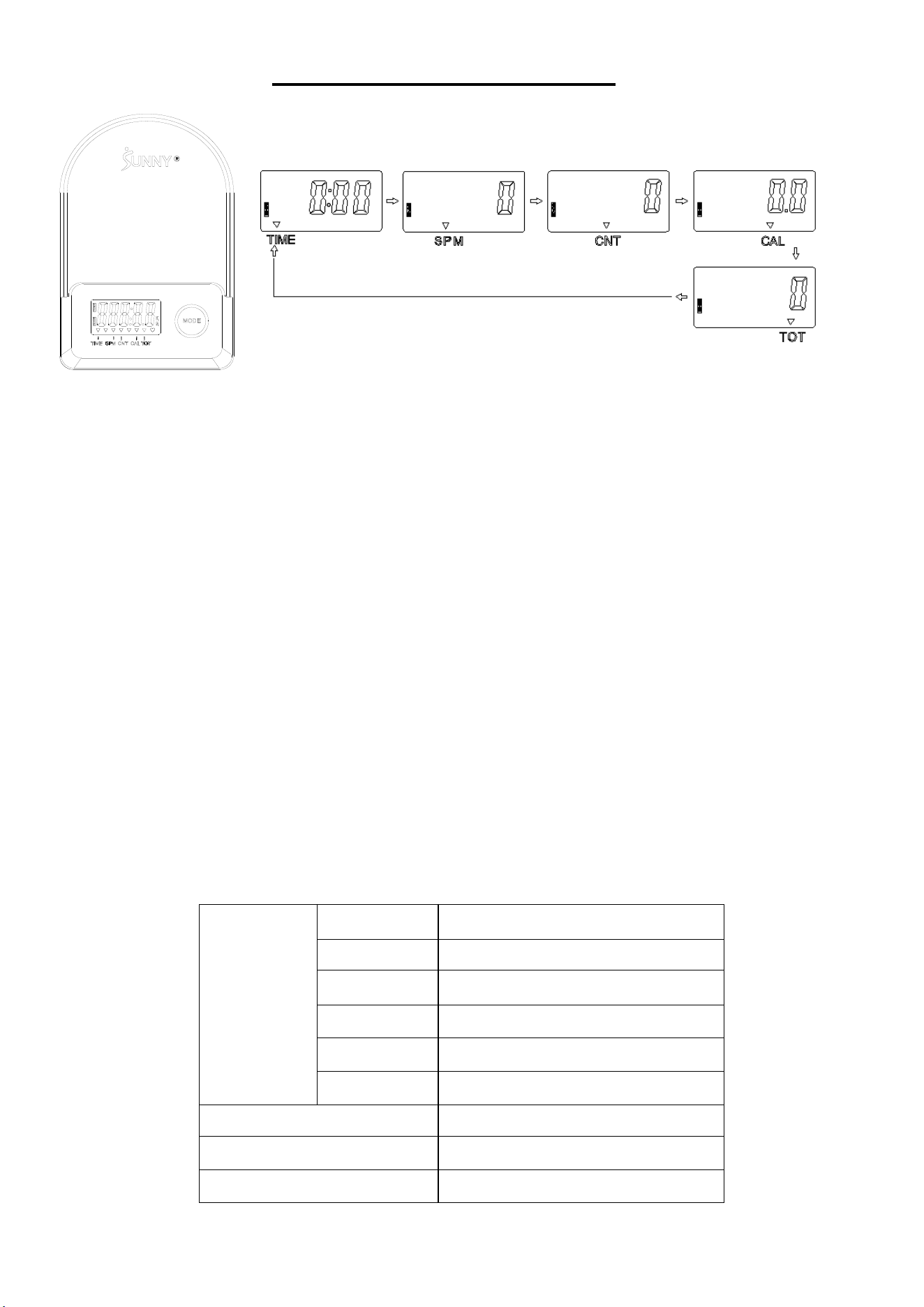
EXERCISE COMPUTER
HEALTH & FITNESS
KEY FUCTIONS:
Pressing the MODE key to select and lock on a function for following sequence:
SCANTIME SPMCNT CAL TOT SCAN
Pressing and hold the MODE key with 3 seconds to reset the value to zero (without TOT).
SLEEP MODE:
The system turns on when the MODE key is depressed or system sensed a signal input from the
sensor.
The system turns off automatically when the sensor has no signal input or no key are pressed for
approximately 4 minutes.
FUNCTIONS:
SCAN : Display changes according to the next diagram every 6 seconds.
TIME: The total working times with starting exercise.
SPM: Number of strokes per minute, indicating the stroke speed during exercise.
CNT: The current count with starting exercise.
CAL: The calorie burned with starting exercise.
TOT: The total count which this function is refers to from battery capacity period runs.
SPECIFICATION:
FUNCTION
SCAN 6S
TIME 999M:59S
COUNT 0~99999
SPM 0~299
TOT 0~99999
CALORIES 0.0~9999.9Kcal
BATTERY SIZE-AAA *2
Operating temperature
0~40℃(32℉-104℉)
Storage temperature
-10~60℃(14℉-140℉)

15
APP CONNECTION:
1. Scan the QR code below to download the SunnyFit app onto your mobile device.
2. If this is your first time using the SunnyFit app, follow the in-app instructions to register for your
free SunnyFit account and log in.
3. Ensure that the Bluetooth function is turned on from your mobile device.
4. To connect the equipment to the SunnyFit app:
a. From the “Workout” tab, press on the “Search” button to search for your equipment.
b. Once your equipment appears on the list, tap the “Select” button to confirm.
c. Note: If your equipment does not appear on the "Searching for Equipment" list, check the
EXERCISE COMPUTER on your equipment to ensure that it is not in sleep mode and your
phone's Bluetooth function is on, then tap "Retry" to search again.
d. Once your equipment shows up on the “Workout” tab as “Currently Selected”, your equipment is
now ready to display, track, and record your equipment’s workout stats on the app!
5. If you are unable to replicate these steps, or have any other issues with the SunnyFit app,
please contact SunnyFit support at support@sunnyfit.com, or use the in-app “Contact Us” form
to request support (“Me” tab -> “Contact Us”).
16
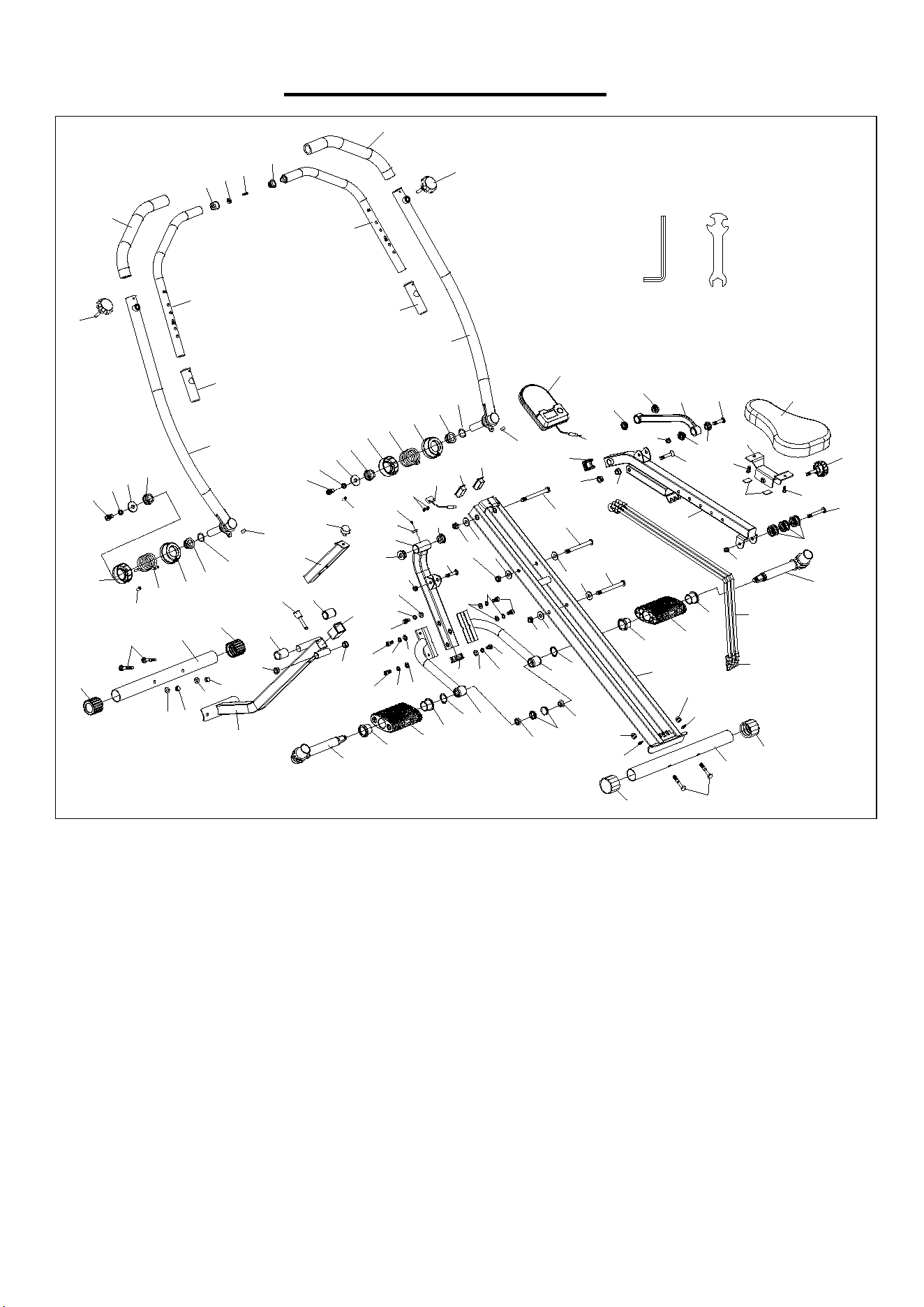
EXPLODED DIAGRAM
71
71
71
71
72
35
38
5
33
37
37
33
5
1
18
21
19
20
20
35
34
5
33
34
23
23
26
27
26
27
26
43
44
6
13
31
42
39
17
16
16
6
12
14
14
14
15
41
7
7
9
8
25
24
36
29
32
30
30
16
16
5
33
11
11
12
6
22
22
A
B
48
45
46
49
64
64
47
47
28
2
3
4
10
10
66
40
66
65
67
68
69
68
70
65
66
40
66
50
51
52
53
54
55
56
53
57
17
54
58
56
53
57
50
51
52
53
2
3
59
60
61
62
63
61
62
63
61
62
63
63
62
61
63
62
61
41A

17
PARTS LIST
No.
Description
Spec.
Qty
No.
Description
Spec.
Qty.
1
Main Frame
1
39
Square Buckle
3
2
Circular Magnet
Φ15*Φ5*5
2
40
Pedal
100.7*46*121
2
3
Bolt
M5*10
2
41
Computer
BJHT-098
1
4
Handle Sheath 1
Φ25*Φ14*12.5
1
41A
Computer Wire
1
5
Washer
Φ16*Φ8*T1.5
4
42
Exercise Band
Φ8*710
3
6
Nut
M8*13
3
43
Bolt
M8*65
1
7
Sponge
Φ29*Φ23*320
2
44
Plastic Wheel
Φ32*Φ8.2*17
3
8 Bushing 30*30*1.5 1 45
Left Upper
Handrail
1
9
Pedal Connecting
Tube
1 46
Right Upper
Handrail
1
10
Knob
Φ52*L56*M12
2
47
Handle Bushing
Φ32*Φ28.5*100
2
11
Powder Metallurgy
Φ28*Φ10.1*13
2
48
Left Handrail
1
12
Hexagon Screw
M8*40.5
2
49
Right Handrail
1
13
Hexagon Screw
M8*50
1
50
Hexagon Screw
M10*20
2
14
Bearing Sleeve
Φ25*3
4
51
Spring Washer
Φ10
2
15 Connecting Tube 1 52 Washer
Φ
32*
Φ
10.5*3.0 2
16 Powder Metallurgy Φ19*Φ10*10.5 4 53 Powder Metallurgy Φ32*Φ19.6*14 4
17 Plug 30*30*1.5 2 54
Lower Spring
Guard
Φ58*Φ33*23 2
18 Seat 1 55 Left Torsion Spring Φ48*Φ5*78 1
19 Fixed Iron Sheet 1 56
Upper Spring
Guard
Φ64*Φ33*26.5 2
20 Screw M6*16 2 57
Corrugated Spring
Pad
Φ20 2
21 Knob Φ47*40*M8 1 58
Right Torsion
Spring
Φ48*Φ5*78 1
22
Plug
40*20*1.5
2
59
Hexagon Screw
S2.9*8
2
23
Bolt
M10*106
3
60
Sensor
L70
1
24
Stopper
Φ25*22.5
1
61
Hexagon Screw
M8*15
6
25
Seat Tube
1
62
Spring Washer
Φ8*1.5
6
26
Washer
Φ10
5
63
Washer
Φ8*Φ20*T1.5
6
27
Nut
M10
3
64
Pedal Tube
2
28
Handle Sheath 2
Φ25*Φ19*16
1
65
Elastic Retainer
Φ25
2
29
Pin
Φ8*42.5
1
66
Pedal Bushing
Φ37*Φ25.5*23
4
30 Plug Φ19*35 2 67
Left Pedal Tube
Assembly
1
31
Seat Connecting
Tube
1 68 Flange Nut M12*1.25 2
32
Front Connecting
Tube
1 69 Crank Cap Cover Φ25*6.5 2
33 Nut M8*12 4 70
Right Pedal Tube
Assembly
1
34
Cap
Φ45.5*39.5
2
71
Rubber Sleeve
Φ8*Φ4*15
4
35
Bolt
M8*48
4
72
EVA mat
25*15*2.0
2
36
Front Stabilizer
Φ38*1.5*410
1
A
Allen Wrench
S6
1
37
End Cap
Φ38
2
B
Spanner
S13-15-17
1
38 Rear Stabilizer
Φ
38*1.5*410 1
Version: 1.0

18