
1
IMPORTANT SAFETY INFORMATION
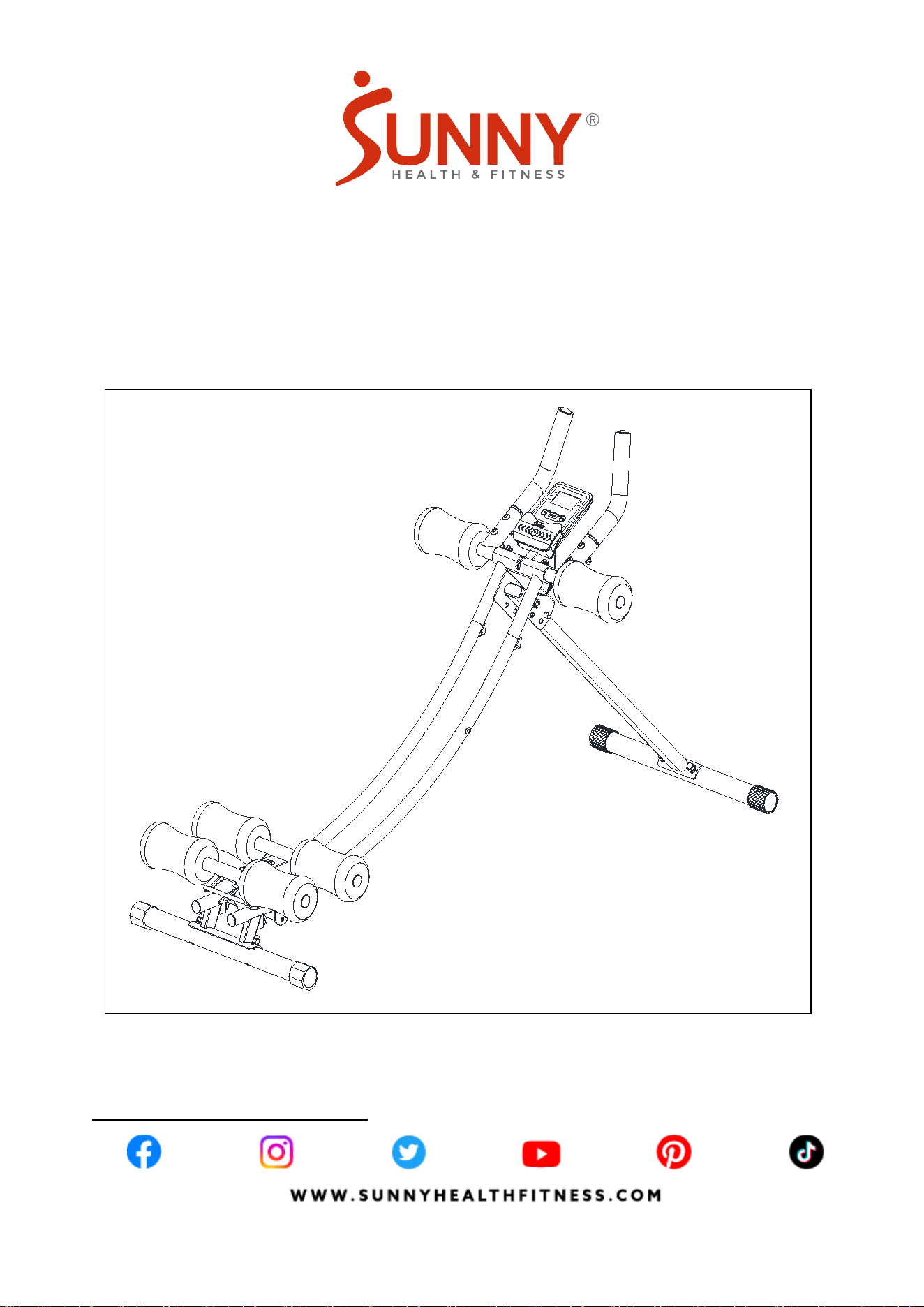
We thank you for choosing our product. To ensure your safety and health, please use this
equipment correctly. It is important to read this entire manual before assembling and using the
equipment. Safe and effective use can only be achieved if the equipment is assembled, maintained,
and used properly. It is your responsibility to ensure that all users of the equipment are informed of
all warnings and precautions.
1. Before starting any exercise program, you should consult your physician to determine if you
have any medical or physical conditions that could put your health and safety at risk or prevent
you from using the equipment properly. Your physician’s advice is essential if you are taking
medication that affects your heart rate, blood pressure, or cholesterol level.
2. Be aware of your body’s signals. Incorrect or excessive exercise can damage your health. Stop
exercising if you experience any of the following symptoms: pain, tightness in your chest,
irregular heartbeat, shortness of breath, lightheartedness, dizziness, or feelings of nausea. If you
do experience any of these conditions, you should consult your physician before continuing with
your exercise program.
3. Keep children and pets away from the equipment. The equipment is designed for adult use only.
4. Use the equipment on a solid, flat level surface with a protective cover for your floor or carpet. To
ensure safety, the equipment should have at least 2 feet (60 CM) of free space all around it.
5. Ensure that all nuts and bolts are securely tightened before using the equipment. The safety of
the equipment can only be maintained if it is regularly examined for damage and/or wear and
tear.
6. Always use the equipment as indicated. If you find any defective components while assembling
or checking the equipment, or if you hear any unusual noises coming from the equipment during
exercise, discontinue use of the equipment immediately and do not use until the problem has
been rectified.
7. Wear suitable clothing while using the equipment. Avoid wearing loose clothing that may
become entangled in the equipment.
8. Do not place fingers or objects into the moving parts of the equipment.
9. The maximum weight capacity of this unit is 220 lbs (100 kgs).
10. The equipment is not suitable for therapeutic use.
11. To avoid bodily injury and/or damage to the product or property, proper lifting and moving are
required.
12. Your product is intended for use in cool and dry conditions. You should avoid storage in extreme
cold, hot or damp areas as this may lead to corrosion and other related problems.
13. This equipment is designed for indoor and home use only; it is not intended for commercial use.
2
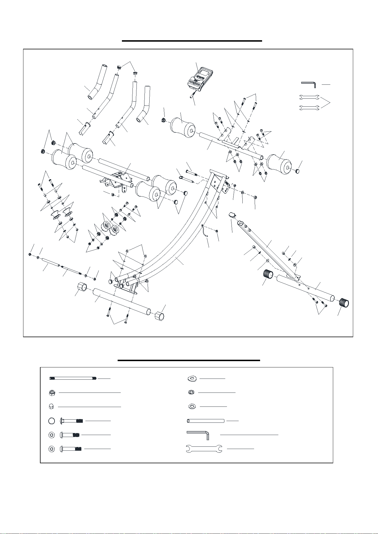
EXPLODED DIAGRAM
HARDWARE PACKAGE
1
2
3
4
5
6
7
8
9
9
10
10
11
12
13
13
13
13
14
14
14
14
15
16
16
16
16
16
17
17
18
18
18
18
19
20
21
21
21
21
21
21
23
23
23
23
22
22
22
22
24
25
25
26
26
26
26
27
28
29
29
29
29
29
29
30
31
32
32
33
33
34
34
35
35
36
37
38
39
40
42
41
38-1
#16 M8 8PCS
#42 S13,S15 2PCS
#41 S6 1PC
#17 M8*50 4PCS
#18 M8*40 4PCS
#19 M8*45 2PCS
#21
φ16*φ
8.5*1.5 10PCS
#22
φ8*φ
13*2.0 6PCS
#23 φ16*φ8.5*1.5 2PCS
#14 M8 2PCS
#36 φ9*φ12*150 1PC
#11 φ8*180 1PC

3
PARTS LIST
No. Description Spec. Qty.
No. Description Spec. Qty.
1
Slide Tube
1
23 Flat Washer
φ16*φ8.5*1.5
6
2 Front Support Tube 1
24 Flat Washer
φ20*φ10.5*2.0
1
3 Slide Seat Support 1
25 Wheel
φ53.5*φ19.4*30
4
4 Hand Support Tube 1
26 Arc Foam
φ90*φ23*160
6
5 Front Stabilizer 1
27 Oval End cap
25*50*1.5
1
6 Rear Stabilizer 1
28
Small Buffer
Column
φ10*11
2
7 Left Handlebar 1
29 End Cap
φ25*1.5
10
8 Right Handlebar 1
30 Plug
φ12.6*φ3
1
9 Sleeve φ12*φ8.2*9 4
31 Mat
φ7.5
2
10 Sleeve φ12*φ8.2*4 4
32 Front End Cap
φ38
2
11 Bolt φ8*180 1
33 Rear End Cap
φ38
2
12 Pin φ10*95 1
34 Inner Bushing
φ32*1.5 & φ25
2
13 Bearing 608Z 8
35 Foam
φ33*φ23*220
2
14 Nylon Nut M8 6
36 Plastic Tube
φ9*φ12*150
1
15 Nylon Nut M10 1
37 Plug
φ12.6*φ6
1
16 Cap Nut M8 8
38 Meter
1
17 Carriage Bolt M8*50 4
38-1
Meter Wire
1
18 Hex Socket Bolt M8*40 8
39 Sensor
1
19 Hex Socket Bolt M8*45 2
40 Magnet
φ16*14
1
20 Hex Socket Bolt M10*90 1
41 Allen Wrench
S6
1
21 Arc Washer Φ16*φ8.5*1.5 10
42 Spanner
S13,S15
2
22 Spring Washer
φ8*φ13*2.0
6
Ordering Replacement Parts (U.S. and Canadian Customers only)
Please provide the following information in order for us to accurately identify the part(s) needed:
The model number (found on cover of manual)
The product name (found on cover of manual)
The part number found on the “EXPLODED DIAGRAM” (page 2) and “PARTS LIST” (page 3).
Please contact us at support@sunnyhealthfitness.com or 1-877-90 SUNNY (877-907-8669).
4
ASSEMBLY INSTRUCTIONS
We value your experience using Sunny Health and Fitness products. For assistance with parts
or troubleshooting, please contact us at support@sunnyhealthfitness.com or 1-877-90SUNNY
(877-907-8669).
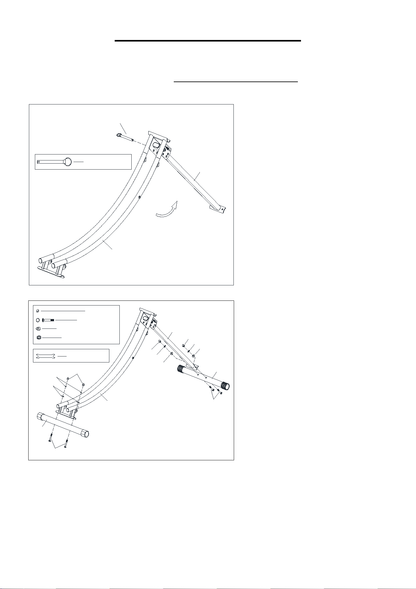
STEP 2:
Attach Rear Stabilizer (No. 6) to Slide
Tube (No. 1) with 2 Carriage Bolts
(No. 17), 2 Arc Washers (No. 21), 2
Spring Washers (No. 22), and 2 Cap
Nuts (No. 16). Tighten and secure
with Spanner (No. 42).
Attach Front Stabilizer (No. 5) to
Front Support Tube (No. 2) with 2
Carriage Bolts (No. 17), 2 Arc
Washers (No. 21), 2 Spring Washers
(No. 22), and 2 Cap Nuts (No. 16).
Tighten and secure with Spanner (No.
42).
STEP 1:
Pull out the Pin (No. 12) form Slide
Tube (No. 1), open the Slide Tube
(No. 1) and Front Support Tube
(No. 2) as indicated by the arrow,
insert the Pin (No. 12) that was pull
out form Slide Tube (No. 1).
12
1
2
#12
φ
10*95 1PC
16
21
22
16
21
22
17
1
2
5
6
17
16
21
22
#16 M8 4PCS
#42 S13,
S15 1PC
#17 M8*50 4PCS
#21
φ16*
φ
8.5*1.5 4PCS
#22 φ8*
φ13*2.0 4PCS
5
We value your experience using Sunny Health and Fitness products. For assistance with parts or
troubleshooting, please contact us at support@sunnyhealthfitness.com or 1-877-90SUNNY
(877-907-8669).
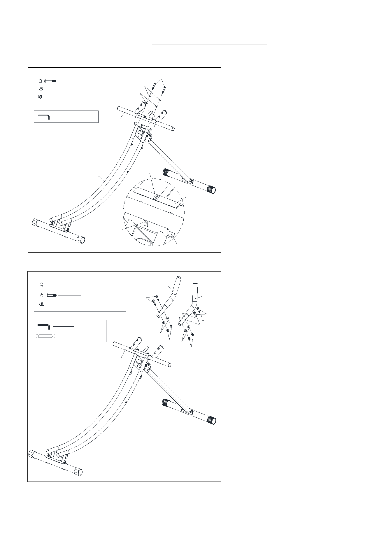
STEP 4:
Attach Left Handlebar (No. 7) and
Right Handlebar (No. 8) to Hand
Support Tube (No. 4) with 4 Hex
Socket Bolts (No. 18), 4 Arc
Washers (No. 21), and 4 Cap Nuts
(No. 16). Tighten and secure with
Allen Wrench (No. 41) and
Spanner (No. 42).
Note: Pay attention to the Left
Handlebar (No. 7) and Right
Handlebar (No. 8) direction.
1
4
19
21
22
#19 M8*45 2PCS
#21
φ16*φ
8.5*1.5 2PCS
#22
φ8*
φ
13*2.0 2PCS
#41 S6 1PC
1
4
C
C
STEP 3:
Attach Hand Support Tube (No. 4)
to Slide Tube (No. 1) with 2 Hex
Socket Bolts (No. 19), 2 Arc
Washers (No. 21), and 2 Spring
Washers (No. 22). Tighten and
secure with Allen Wrench (No. 41).
NOTE:
To properly install handlebar, make
sure the arrows on the Hand
Support Tube (No. 4) & Side Tube
(No. 1) are on the same side and
pointing to each other.
18
21
16
16
21
7
8
18
4
#18 M8*40 4PCS
#21 φ16*
φ8.5*1.5 4PCS
#41 S6 1PC
#16 M8 4PCS
#42 S13,S15 1PC
6
We value your experience using Sunny Health and Fitness products. For assistance with parts or
troubleshooting, please contact us at support@sunnyhealthfitness.com or 1-877-90SUNNY
(877-907-8669).
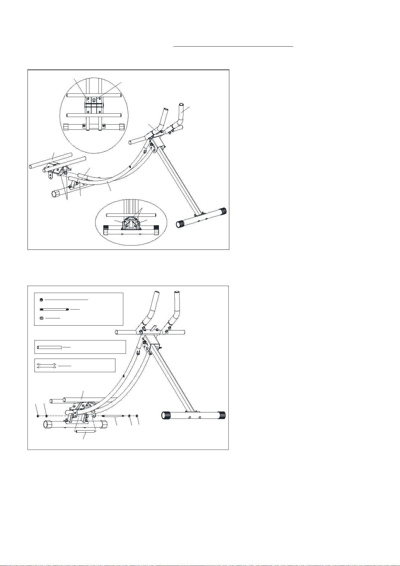
STEP 5:
Insert the Slide Seat Support
(No. 3) into the Slide Tube (No.
1), the 4 Wheels (No. 25) are
over the Left Slide Tube (No. 1L)
and Right Slide Tube (No. 1R).
NOTE: The arrow of the UP Label
(D) on the Slide Seat Support
(No. 3) should point to the Left
Handlebar (No. 7) & Right
Handlebar (No. 8) when
assembly.
STEP 6:
Attach Bolt (No. 11) through
Plastic Tube (No. 36) to the Slide
Seat Support (No. 3) with 2 Flat
Washer (No. 23), and 2 Nylon
Nut (No. 14). Tighten and secure
with Spanner (No. 42).
3
11
14
23
36
14
23
#42 S13
,
S15 2PCS
#11
φ
8*180 1PC
#23
φ16*φ
8.5*1.5 2PCS
#14 M8 2PCS
#36
φ
9*
φ
12*150 1PC
25
1L 1R
1
1R
1L
25
3
7
8
3
D
7
We value your experience using Sunny Health and Fitness products. For assistance with parts or
troubleshooting, please contact us at support@sunnyhealthfitness.com or 1-877-90SUNNY
(877-907-8669).
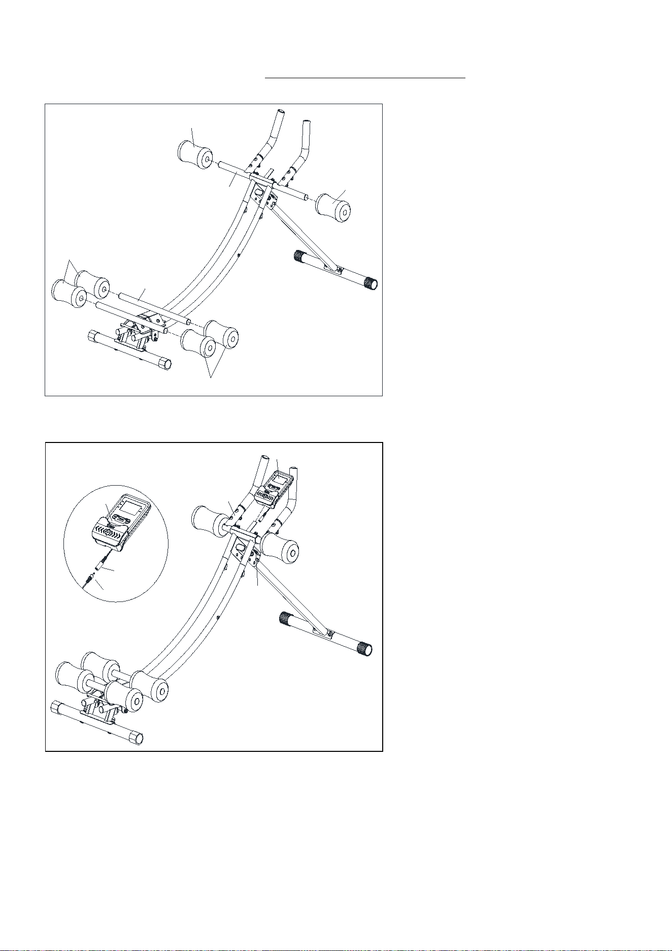
STEP 7:
Attach 6 Arc Foams (No. 26) to
Hand Support Tube (No. 4) and
Slide Seat Support (No. 3) by
hand.
STEP 8:
Connect the Meter Wire (No. 38-1)
to the Sensor (No. 39). Insert the
Meter (No. 38) into the Hand
Support Tube (No. 4).
The assembly is complete!
3
26
26
4
26
26
4
38
39
38
39
38-1
8
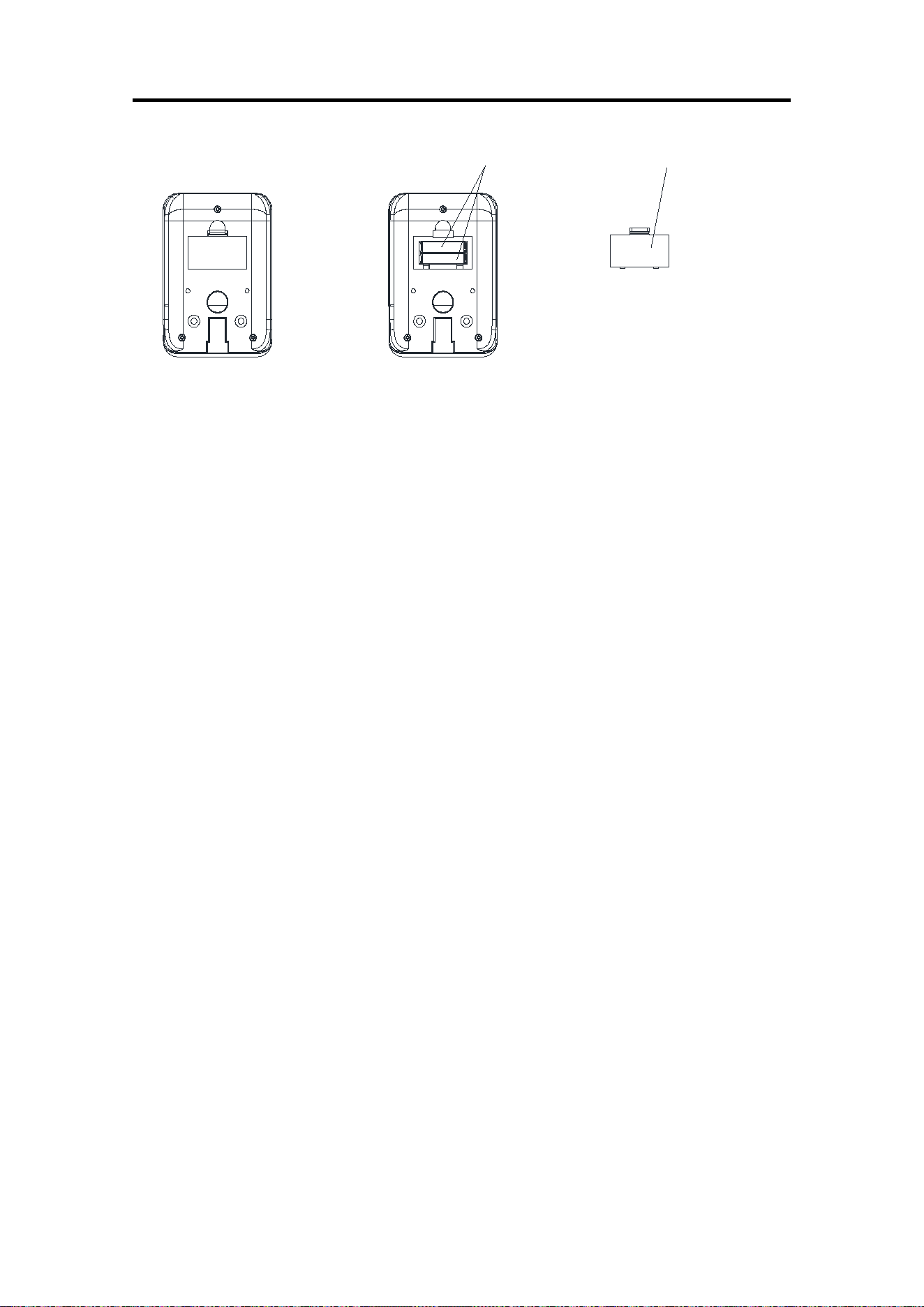
BATTERY INSTALLATION & REPLACEMENT
BATTERY INSTALLATION:
1. Take out 2 AAA battery from meter box.
2. Press the buckle of battery cover on the Meter (No. 38), then remove battery cover.
3. Install 2 AAA battery into the battery case on the back of the Meter (No. 38). Pay attention to the
battery + and – ends before installing.
4. Press the buckle of battery cover, then put the battery cover back to the back of the Meter (No.
38).
The installation is complete!
BATTERY REPLACEMENT:
1. Press the buckle of battery cover on the back of the Meter (No. 38), then remove battery cover.
2. Remove the 2 old AAA battery in the battery case and install 2 new AAA battery into the battery
case on the back of the Meter (No. 38). Pay attention to the battery + and – ends before
installing.
3. Press the buckle of battery cover, then put the battery cover back to the back of the Meter (No.
38).
The replacement is complete!
NOTE: Always change both batteries at the same time. Do not mix battery types and do not mix old
and new batteries. Dispose batteries according to your state and regional guidelines.
Battery Battery Cover
9
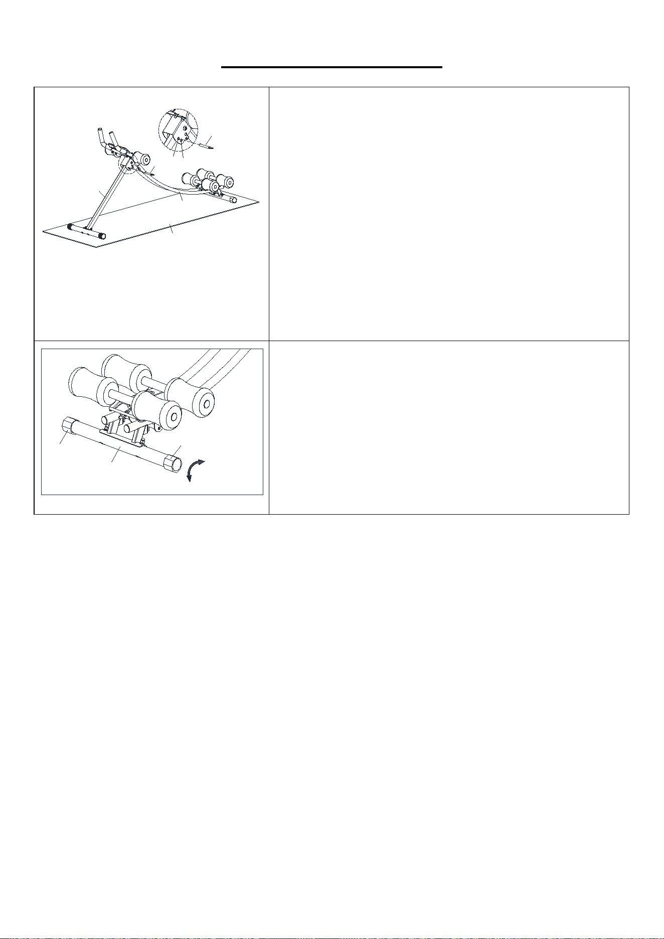
ADJUSTMENTS GUIDE
SLOPE ADJUSTMENT
This machine has 2 stages of slope adjustment.
Open the Slide Tube (No. 1) and Front Support Tube (No. 2),
Insert Pin (No. 12)
to the hole A or hole B accordingly and then can
adjust slope of Slide Tube (No. 1) and Ground (H).
When the Pin (No. 12) is inserted into the hole B, it has a higher
movement slope than the Pin (No. 12) inserted into the hole A,
thereby enhancing the exercise intensity.
NOTE: Pay attention to the Pin (No. 12) must be inserted to Slide
Tube (No. 1) when using the machine.
BALANCE ADJUSTMENT
During use, if you notice the machine is not balance, you can
adjust the Rear End Caps (No. 33) to direction A or B until the
machine is balance.
1
2
12
12
A
B
H
33
33
6
A
B
10
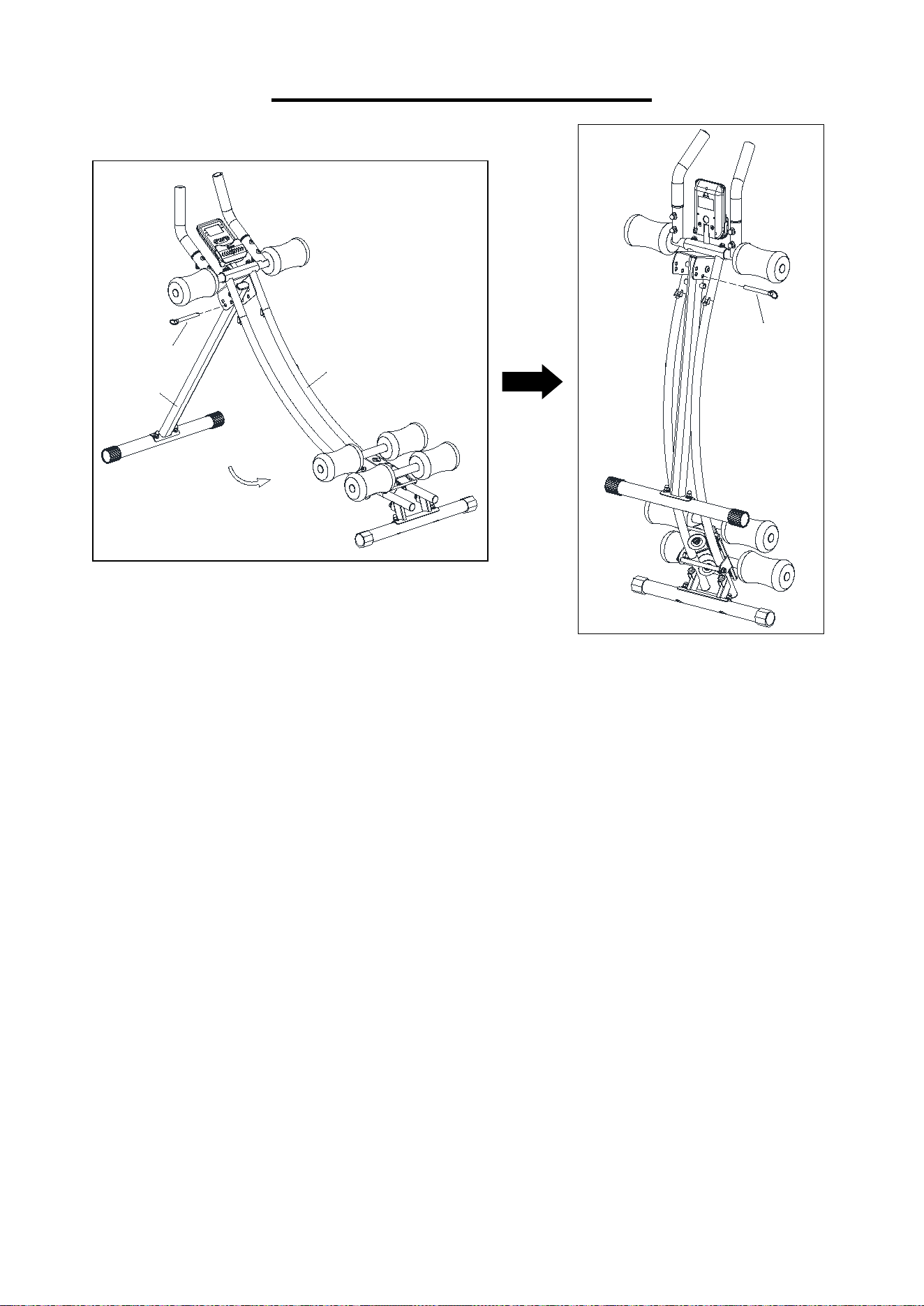
FOLDING INSTRUCTIONS
12
2
1
Pull out the Pin (No. 12) from Slide Tube (No. 1), fold the Front Support Tube (No. 2)
into Slide Tube (No. 1) in the direction indicated by the arrow above, and then insert the
Pin (No. 12) into Slide Tube (No. 1).
12
11
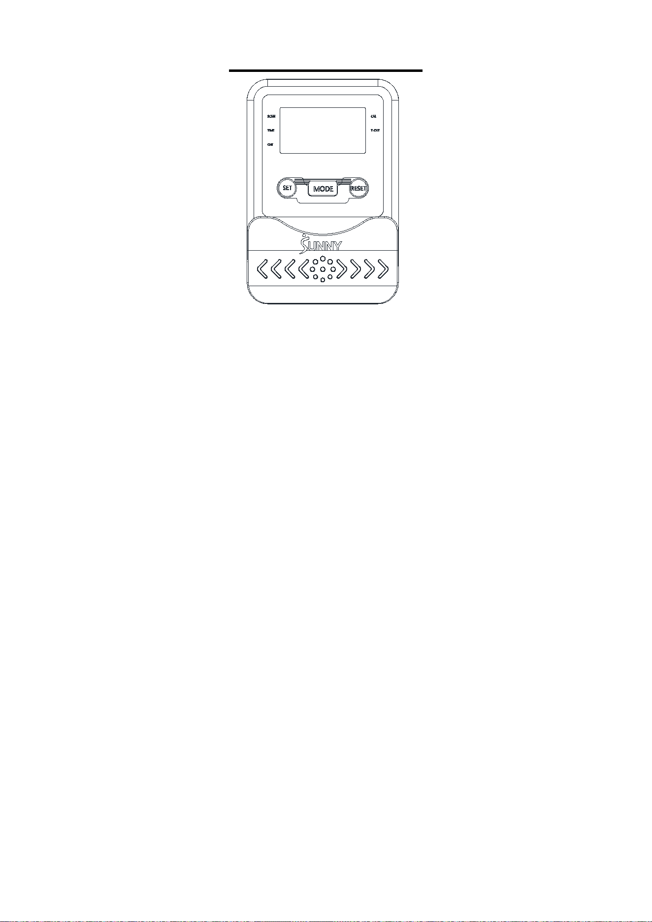
EXERCISE METER
FUNCTIONAL BUTTONS:
MODE: Push down for selecting functions. If the long time holds down MODE button down for
resetting time count and calories.
SET: To set the values of TIME, COUNT and CAL when not in scan mode.
RESET: Push down for resetting TIME, COUNT and CAL.
FUNCTION AND OPERATIONS:
1. SCAN:
Press “MODE” button until “SCAN” appears, monitor will rotate through all the 4 functions:
TIME, CAL, COUNT, T.CNT, each display will be hold 6 seconds.
2. TIME:
(1) Count the total time from exercise start to end.
(2) Press “MODE” button until “TIME” appears, press “SET” button to set exercise time.
When the “SET” is zero, the meter will stop 1 second after the start of the time.
3. COUNT:
(1) Accumulate the counts while exercising.
(2) Press “MODE” button until “Count” appears, Press “SET” button to set exercise Count.
When the “SET” is zero, the meter will stop about 1 second after the start of the time.
4. T.CNT:
Display the counts you have exercised.
5. CAL:
(1) Count the total calories from exercise start to end.
(2) Press “MODE” button until “CAL” appears, Press “SET” button to set exercise calories.
When the “SET” is zero, the meter will stop about 1 second after the start of the time.

12
NOTE:
1. If the display is faint or shows no figures, please replace the batteries.
2. The meter will automatically shut off if there is no signal received after 2 minutes.
3. When there is signal input, the meter automatically turns on.
4. The meter will automatically start calculating when you start to exercise and will stop
calculating when you stop exercising for 4 seconds.
SPECIFICATIONS:
FUNCTION
SCAN
Every 4 seconds
TIME
00:00′~99:59′
COUNT
0-9999
T.CNT
0-9999
CAL
0.0~999.9KCAL
BATTERY TYPE
2pcs of SIZE –AAA or UM –4
OPERATING
32°F~+104°F
STORAGE TEMPERATURE
14°F~+140°F
Version: 1.2