Loading ...
Loading ...
Loading ...
overview
16_ overview
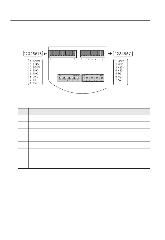
Camera Wiring Interface Board
For the camera wiring, please refer to the picture below. When using coaxial
communication, a separate control signal connection is not required.
Controller & Auxiliary Signal Connection
No. Name Usage
1 2.COM Alarm Output 2 (Common)
2 2.NO Alarm Output 2 (Normal Open)
3 1.COM Alarm Output 1 (Common)
4 1.NO Alarm Output 1 (Normal Open)
5 1.NC Alarm Output 1 (Normal Open)
6 GND Ground
7 IN1 Alarm Input Sensor Terminal 1
8 IN2 Alarm Input Sensor Terminal 2
❖
ALARM
ID PROTOCOL
VIDEO 485 POWER
Loading ...
Loading ...
Loading ...